US20030192526A1 - Portable cooking apparatus - Google Patents
Portable cooking apparatus Download PDFInfo
- Publication number
- US20030192526A1 US20030192526A1 US10/444,237 US44423703A US2003192526A1 US 20030192526 A1 US20030192526 A1 US 20030192526A1 US 44423703 A US44423703 A US 44423703A US 2003192526 A1 US2003192526 A1 US 2003192526A1
- Authority
- US
- United States
- Prior art keywords
- fire bowl
- lid
- shelf
- stand
- during
- Prior art date
- Legal status (The legal status is an assumption and is not a legal conclusion. Google has not performed a legal analysis and makes no representation as to the accuracy of the status listed.)
- Granted
Links
Images


Classifications
-
- A—HUMAN NECESSITIES
- A47—FURNITURE; DOMESTIC ARTICLES OR APPLIANCES; COFFEE MILLS; SPICE MILLS; SUCTION CLEANERS IN GENERAL
- A47J—KITCHEN EQUIPMENT; COFFEE MILLS; SPICE MILLS; APPARATUS FOR MAKING BEVERAGES
- A47J37/00—Baking; Roasting; Grilling; Frying
- A47J37/06—Roasters; Grills; Sandwich grills
- A47J37/07—Roasting devices for outdoor use; Barbecues
- A47J37/0704—Roasting devices for outdoor use; Barbecues with horizontal fire box
-
- A—HUMAN NECESSITIES
- A47—FURNITURE; DOMESTIC ARTICLES OR APPLIANCES; COFFEE MILLS; SPICE MILLS; SUCTION CLEANERS IN GENERAL
- A47J—KITCHEN EQUIPMENT; COFFEE MILLS; SPICE MILLS; APPARATUS FOR MAKING BEVERAGES
- A47J37/00—Baking; Roasting; Grilling; Frying
- A47J37/06—Roasters; Grills; Sandwich grills
- A47J37/07—Roasting devices for outdoor use; Barbecues
- A47J37/0763—Small-size, portable barbecues
-
- A—HUMAN NECESSITIES
- A47—FURNITURE; DOMESTIC ARTICLES OR APPLIANCES; COFFEE MILLS; SPICE MILLS; SUCTION CLEANERS IN GENERAL
- A47J—KITCHEN EQUIPMENT; COFFEE MILLS; SPICE MILLS; APPARATUS FOR MAKING BEVERAGES
- A47J37/00—Baking; Roasting; Grilling; Frying
- A47J37/06—Roasters; Grills; Sandwich grills
- A47J37/07—Roasting devices for outdoor use; Barbecues
- A47J37/0704—Roasting devices for outdoor use; Barbecues with horizontal fire box
- A47J37/0713—Roasting devices for outdoor use; Barbecues with horizontal fire box with gas burners
-
- A—HUMAN NECESSITIES
- A47—FURNITURE; DOMESTIC ARTICLES OR APPLIANCES; COFFEE MILLS; SPICE MILLS; SUCTION CLEANERS IN GENERAL
- A47J—KITCHEN EQUIPMENT; COFFEE MILLS; SPICE MILLS; APPARATUS FOR MAKING BEVERAGES
- A47J37/00—Baking; Roasting; Grilling; Frying
- A47J37/06—Roasters; Grills; Sandwich grills
- A47J37/07—Roasting devices for outdoor use; Barbecues
- A47J37/0786—Accessories
Definitions
- the present invention relates to a portable cooking apparatus and more particularly, a cooking apparatus comprising a fire bowl having an exterior undersurface; a lid removably engagable with the fire bowl; and a stand located against the undersurface of the fire bowl during a usage position, and the stand being situated atop the lid, which is situated atop the fire bowl during a non-use position.
- cooking apparati of the prior art that have planar or slightly bowed sidewalls have not been designed to be an effective cooking instrument. If a fire bowl has an arcuate curved bottom wall, it will facilitate the reflection of heat toward the cooking grill. Previously, fire bowls of cooking apparati that have planar or slightly bowed sidewalls have not been properly designed in order to maximize the application of heat of the cooking grill.
- the present invention provides a portable cooking apparatus and system designed to be compact and functional during storage and transport and to provide convertible workspace during usage of the barbecue.
- the present invention relates to a cooking apparatus comprising a fire bowl and at least one shelf pivotally mounted to the fire bowl, wherein the shelf is movable between a stowage position within the fire bowl to a usage position located externally of the fire bowl.
- the fire bowl has an internal chamber and the apparatus further comprises a grill located within the internal chamber.
- the apparatus has a second shelf pivotally mounted to the fire bowl, wherein the second shelf is movable between a stowage position within the fire bowl to a usage position located exteriorly of the fire bowl.
- the first shelf is aligned with the second shelf in both the stowage position and the usage position.
- fire bowl terminates into at least one end portion and the shelf is pivotally mounted to the end portion.
- the fire bowl is mounted on a supporting frame and the apparatus further comprises at least one leg.
- the fire bowl is mounted on a supporting frame, and the supporting frame has at least one handle, and the shelf rests on the handle when the shelf is in the usage position.
- the supporting frame includes a pair of leg members, each of the leg member are pivotally movable between a retracted position and an extended position, and the leg members are adapted to be in contact with the supporting surface in both the retracted position and the extended position, and the fire bowl is located further from the supporting surface when the leg members are in the extended position as opposed to the retracted position.
- the shelf in the usage position has a working surface.
- the shelf comprises at least one utensil retaining groove.
- the shelf has a working surface in the usage position and a utensil is to be located within the utensil retaining groove so the utensil is located beneath the working surface when the shelf is in the usage position.
- a utensil includes, but is not limited to, spatula, forks, and tongs.
- the first and second shelves have utensil storage grooves, which function to provide utensil storage locations when the first and second shelves are in the storage position.
- the apparatus comprises a lid mountable on the fire bowl.
- the lid is pivotally mounted to the fire bowl, and the lid being movable in a closed position wherein the lid covers the grill to an open position wherein the lid allows access to the grill.
- the supporting frame of the apparatus includes a pair of main frame members, each the main frame member are channel shaped defining an internal cavity, and the leg is mounted within the internal cavity.
- the first shelf is situated atop the second shelf in a staggered position during the stowage position.
- the shelf rests upon the grill during the stowage position.
- the barbecue cooking system comprises a fire bowl having an internal chamber, a grill located within the internal chamber; a lid mountable on the fire bowl; a stand for supporting the fire bowl; and at least one shelf pivotally mounted to the fire bowl, the shelf being foldable into the fire bowl during a storage position and extendable from the fire bowl during a usage position.
- the system is a stationary cooking system. In another embodiment, the system is a portable cooking system.
- the cooking apparatus and system of the present invention may be used for indoor and outdoor use.
- system further comprising a second shelf pivotally mounted to the fire bowl, the second shelf being foldable into the fire bowl during a stowage position and extendable from the fire bowl during a usage position.
- first shelf is aligned with the second shelf in both the storage position and the usage position.
- the shelf comprises at least one working surface and at least one utensil retaining grooves.
- the stand comprises at least one movable leg.
- the leg is retractable and extendable.
- the leg terminates into a wheel.
- the fire bowl is situated upon the stand during a usage position and the stand being designed to fit onto the lid during a stowage position.
- the lid is pivotally mounted onto the fire bowl, the lid being movable from a closed position wherein the lid covers the grill to an open position wherein the lid allows access to the grill.
- the internal chamber comprises a compartment for retaining burnable material such as coal.
- the system further comprises a manually operated tightening device and a latching device.
- the tightening device is any device designed for securing the leg when the leg is an extended position.
- tightening device include, but is not limited to, screws, bolts and other fasteners.
- the latching device is any device designed for cocking the leg in the retracted position.
- latching devices is any device designed for locking the leg in the retracted position.
- the system further comprising a propane tank, the tank is situated within the fire bowl during the stowage position and externally of the fire bowl during the usage position.
- the system further comprising at least one utensil, the utensil is positioned within the utensil retaining groove of the shelf.
- the fire bowl having a bottom which is connected to a pair of planar sidewalls with the bottom being located between the sidewalls, the bottom has an arcuate shape which extends from a fore end to an aft end, the sidewalls having a free upper edge which is substantially flush with the fore end and the aft end.
- the shelf is foldable into the internal chamber of the fire bowl.
- the present invention relates to a cooking apparatus comprising: a fire bowl having an internal chamber, a grill located within the internal chamber; a lid mountable on the fire bowl; and at least two shelves, each of the shelves are pivotally mounted to the fire bowl, each of the shelves being movable between a stowage position within the fire bowl to a usage position located exteriorly of the fire bowl.
- the first shelf is situated atop the second shelf in a staggered position during a stowage position.
- the apparatus further comprising a stand, the fire bowl being situated upon the stand during a usage position, the stand being design to fit onto the lid during a stowage position.
- at least one of said shelves of the apparatus of present invention rests upon the grill during the stowage position.
- the present invention relates to a cooking apparatus comprising: a fire bowl; and a supporting frame being mounted on the fire bowl, at least one pair of leg members being pivotally mounted on the supporting frame and movable between a retracted position and an extended position, the leg members adapted to be in contact with a supporting surface in both the retracted and extended positions, the fire bowl being located further from the supporting surface when the leg members are in the extended position as opposed to the retracted position.
- the leg members are crossed when in the retracted position.
- the leg members are located parallel and spaced apart when in the extended position.
- the present invention relates to a method of manufacturing a cooking apparatus, the method comprising: providing a fire bowl having an internal chamber; positioning a grill within the internal reservoir; and pivotally mounting at least one shelf onto the fire bowl, the shelf being movable between a stowage position within the fire bowl to a usage position located exteriorly of the fire bowl.
- the present invention relates to portable cooking apparatus comprising: a fire bowl comprising an exterior undersurface and an internal chamber; a lid removably engagable with the fire bowl; and a stand to be locatable against the exterior undersurface of the fire bowl for support during a usage position, and during a non-use position, the stand is situated atop the lid while the lid is situated atop the fire bowl to thereby enclose the internal chamber of the fire bowl.
- the stand during the non-use position is attached and secured onto the fire bowl.
- the lid during the non-use position is attached and secured onto the fire bowl and the stand is secured onto the lid.
- the fire bowl comprises at least one groove and the lid comprises a peripheral lip with widened areas, the widened areas of the lid are designed to engage the groove during the non-use position and thereby form a locking action therebetween.
- the fire bowl comprises at least one handle and the groove is situated on the handle.
- the fire bowl comprises an external protrusion and the groove is situated on the protrusion.
- the lid comprises at least one handle and the stand comprises an aperture designed to fit over the handle when the stand is situated atop the lid during the non-use position and thereby allowing user access to the handle.
- the fire bowl comprises a plurality of legs situated on the external undersurface.
- the cooking apparatus further comprises at least one shelf, the shelf being movable between a stowage position within the fire bowl to a usage position located externally of the fire bowl.
- the shelf is pivotably mounted to the fire bowl.
- the fire bowl comprises at least one handle and the shelf is pivotably mounted to the handle.
- the cooking apparatus further comprises a first and second shelf, the shelves are foldable into the fire bowl during a storage position and extendable from the fire bowl during a usage position, the first shelf is aligned with the second shelf in both the storage position and the usage position.
- the shelf comprises at least one working surface and at least one undersurface for retaining utensils.
- the undersurface of the shelf comprises at least one groove for retaining the utensil.
- the undersurface of the shelf comprises a means for securing the utensil to the undersurface.
- the means can be an mechanism or device that can retain and secure the utensils on the undersurface of the shelf including, but not limited to, straps, metal bars, grooves, cut-outs, elastics, etc.
- the fire bowl comprises a convex undersurface and a concave internal chamber
- the stand comprises a convex outer surface and a concave internal cavity
- the convex undersurface of the fire bowl is in contact with the convex outer surface of the stand.
- the lid comprises a convex outer surface, and during the non-use position, the concave internal cavity of the stand is situated atop the convex outer surface of the lid.
- the cooking apparatus of the present invention further comprises at least one adjustable air vent plate and an ash collecting container.
- the present invention relates to a portable cooking apparatus comprising: a fire bowl comprising an exterior undersurface and an internal chamber; a lid removably engagable with the fire bowl; and a stand to be locatable against the exterior undersurface of the fire bowl for support during a usage position, and during a non-use position, the lid is situated atop the fire bowl to thereby enclose the internal chamber of the fire bowl while the stand is situated underneath the fire bowl.
- the present invention also relates to a portable cooking apparatus comprising: a fire bowl comprising an exterior undersurface and an internal chamber; a lid removably engagable with the fire bowl; and a stand to be locatable against the exterior undersurface of the fire bowl for support during a usage position, and during a non-use position, the stand is situated atop the fire bowl while the lid is situated underneath the stand thereby enclosing the stand within the internal chamber of the fire bowl.
- FIG. 1 is an isometric view of the cooking apparatus of the present invention showing the first embodiment of the cooking apparatus in its most compact position with the lid being mounted on the fire bowl and the leg assembly of the supporting frame in a retracted position;
- FIG. 2 is a cross-sectional view through the leg assembly of the supporting frame of the first embodiment of the cooking apparatus of the present invention taken along line 2 - 2 of FIG. 1;
- FIG. 3 is an isometric view of the first embodiment of the cooking apparatus of the present invention showing the lid removed and also showing a propane tank and utensils being mounted in a stowed position in conjunction with a pair of shelves that are also located in a stowage position on the grill of the first embodiment of the cooking apparatus and with the leg assembly of the supporting frame being located in the extended (usage) position;
- FIG. 4 is a cross-sectional view through the leg assembly taken along line 4 - 4 of FIG. 3;
- FIG. 5 is an isometric view of the cooking apparatus of this invention showing such in its typical usage position
- FIG. 6 is an isometric view of a second embodiment of cooking apparatus of this invention showing the second embodiment of cooking apparatus in its most compact position with the lid being mounted on the fire bowl and the leg assembly of the supporting frame in the retracted position;
- FIG. 7 is a cross-sectional view through the lid latching assembly of the second embodiment of cooking apparatus of this invention taken along line 7 - 7 of FIG. 6 with this latching assembly being also employed within all embodiments of this invention that utilize a propane tank;
- FIG. 8 is an isometric view of the second embodiment of cooking apparatus of this invention showing the lid removed and also showing the propane tank and utensils being mounted in a stowed position in conjunction with a pair of shelves that are also located in a stowage position on the grill of the second embodiment of cooking apparatus and with the leg assembly of the supporting frame being located in the extended (usage) position;
- FIG. 9 is an isometric view of the second embodiment of cooking apparatus of this invention with the pair of shelves being moved to an outwardly extended position and the second embodiment of cooking apparatus in position for usage;
- FIG. 10 is an isometric view of a third embodiment of cooking apparatus of this invention showing the third embodiment of cooking apparatus in its most compact position with the lid being mounted on the fire bowl and the leg assembly of the supporting frame in a retracted position;
- FIG. 11 is a cross-sectional view taken along line 11 - 11 of FIG. 10 showing the mounting arrangement between the fire bowl which is not only used in conjunction with the third embodiment of this invention, but is also used within the first and second embodiments of this invention;
- FIG. 12 is a cross-sectional view similar to FIG. 11 showing the lid being disengaged from the fire bowl where in FIG. 11 the lid was engaged with the fire bowl;
- FIG. 13 is a cross-sectional view through the latching mechanism for the leg assembly of the third embodiment of cooking apparatus of this invention taken along line 13 - 13 of FIG. 10;
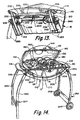
- FIG. 14 is an isometric view of the third embodiment of cooking apparatus of this invention showing the lid in an open position and the leg assembly in the extended position, which is the normal position for usage of the cooking apparatus;
- FIG. 15 is an isometric view of the fire bowl of the third embodiment of the cooking apparatus of this invention showing the shelves being moved from the stowage position to an outwardly extended position which would be the normal usage position of the third embodiment of this invention;
- FIG. 16 is an isometric view of a fourth embodiment of cooking apparatus of this invention showing the fourth embodiment of cooking apparatus in its most compact position with the lid being mounted on the fire bowl and a supporting base being mounted in conjunction about the lid and latched to the handle assembly that is mounted on the fire bowl;
- FIG. 17 is an exploded isometric view of the fourth embodiment of cooking apparatus of this invention showing the supporting base removed from the lid and placed underneath the fire bowl with the lid disengaged from the fire bowl;
- FIG. 18 is an isometric view of-the fourth embodiment of cooking apparatus of this invention showing the lid removed and showing the pair of shelves in conjunction with the fourth embodiment of cooking apparatus being moved to the extended position which is a position of usage and also showing the fire bowl being supported on the supporting base.
- the fire bowl 12 has a bottom 14 .
- the fire bowl 12 will be constructed of steel or iron.
- the bottom 14 assumes a smooth, arcuate shape so that the bottom 14 is basically concave relative to the internal chamber 16 of the fire bowl 12 .
- the fire bowl 12 also includes a front 18 and a back 20 .
- the sides of the front and back, 18 and 20 respectively, of the fire bowl 12 are slightly curved being convex from the exterior.
- the bottom 14 is also curved arcuately in the direction from front 18 to back 20 .
- This forming of the fire bowl 12 is to maximize the reflecting or application of heat from the heating unit 22 that is contained within the internal chamber 16 .
- Mounted at the upper end of the internal chamber 16 is a cooking grill 24 . It is to be noted that the upper edge of the front 18 and back 20 are substantially flush to the upper edge of the left side 26 and the right side 28 of the fire bowl 12 .
- the bottom 14 of the fire bowl 12 is fixedly mounted onto a supporting frame 30 .
- the supporting frame 30 includes a pair of parallel, spaced apart arcuate main members 32 and 34 , which are in a bowl shape resembling a basic cradle configuration. Within that cradle is mounted the fire bowl 12 . Extending between the members 32 and 34 are cross braces 36 and 38 .
- the fire bowl 12 is fixedly mounted onto the cross braces 36 and 38 by mounts 40 .
- One end of the supporting frame 30 terminates in a handle 42 with the opposite end of the supporting frame 30 terminating in a handle 44 .
- the handle 42 is located directly adjacent but slightly spaced from the left side 26 .
- the handle 44 is located directly adjacent but slightly spaced from the right side 28 .
- the main member 32 is basically configured to be channeled shaped having an internal cavity 46 .
- This cavity 46 is open at the bottom.
- a leg assembly composed of leg members 48 and 50 is to be mounted between the main members 32 and 34 .
- the leg member 48 is pivotally mounted by pivot pins, 52 and 54 respectively, to the main members 32 and 34 .
- the leg member 48 includes legs 56 and 58 with leg 56 being pivotally mounted by the pivot pin 52 to the main member 32 and leg member 58 being pivotally mounted by the pivot pin 54 to the main member 34 .
- the outer end of the legs 56 and 58 has extending therebetween a cross member 60 .
- the leg member 50 includes a similar pair of legs with only leg 62 being shown.
- the leg 62 is pivotally mounted by a pivot pin 64 to the main member 32 .
- Extending between the legs 62 and the not shown leg of the leg member 50 is a cross member 66 .
- the leg members 48 and 50 can be located in a retracted position relative to the supporting frame 30 which will locate the cross member 60 in conjunction with a notch 68 formed within the main member 32 and the cross member 66 engaging with a notch 70 formed within the main member 32 .
- the leg member 48 With the leg members 40 and 50 in this retracted position, the leg member 48 includes a pair of leg extensions 72 and 74 which are to be located on a supporting surface 76 . It is to be noted that in this position the main members 32 and 34 will be located also very near the supporting surface 76 , generally no more than a fraction of an inch therefrom.
- the leg member 50 also includes a similar pair of leg extensions with only leg extension 78 being shown.
- leg member 48 When the leg member 48 is moved clockwise to an extended position, and the leg member 50 moved counterclockwise to an extended position, the leg member 78 moves within the internal cavity 46 of the main member number 32 . When the leg extension 78 contacts the upper end of the internal cavity 46 , this will define the limit of movement of the leg member 50 to the extended position. Such also is to occur for the leg member 48 with the leg extensions 72 and 74 as well as the not shown leg extension for leg member 50 . It is to be noted when the leg members 48 and 50 are in the retracted position, the shape of the legs 56 , 58 , 62 and the not shown leg of leg member 50 will nest within the internal cavity 46 in a close conforming manner of the main members 32 and 34 respectively.
- leg members 40 and 50 will automatically remain in their retracted position until such is moved from the retracted position to the extended position.
- the extended position of the leg members 48 and 50 locates the outer end of the leg members 48 and 50 against the supporting surface 76 .
- a mounting bar 80 Fixedly mounted to the fire bowl 12 at the fore end 26 is a mounting bar 80 .
- a similar mounting bar 82 is fixedly mounted to the fire bowl 12 at the aft end 28 .
- Mounted on the mounting bar 80 is a pivot rod 84 .
- a similar pivot rod 86 is pivotally mounted on the mounting bar 82 .
- Connected to the pivot rod 84 is the inner end of a first shelf 88 .
- the inner end of a second shelf 90 is connected to the pivot rod 86 .
- the first shelf 88 is capable of being pivoted from a stowage position located within the confines of the internal chamber 16 shown in FIG. 3 of the drawings to an extended position, which is shown in FIG. 5 of the drawings.
- the second shelf 90 is capable of being pivoted one hundred eighty degrees from the stowage position shown in FIG. 3 to an extended position shown in FIG. 5.
- the shelves 88 and 90 are located in juxtaposition and in alignment.
- the shelves 88 and 90 are no longer in juxtaposition but still in alignment.
- the shelf 88 has a planar working surface 92
- shelf 90 has a planar working surface 94 .
- the bottom side of the shelves 88 and 90 is what are located in an upward facing direction when the shelves 88 and 90 are in the stowage position shown in FIG. 3.
- the undersurface of the shelves 88 and 90 includes a plurality of spaced-apart brace members 96 each of which includes notches 98 . These notches 98 are to facilitate stowage of utensils, such as a spatula 100 , tongs 102 and a fork 104 .
- the gas tank 106 can be removed and mounted on the supporting surface 76 in close proximity to the fire bowl 12 .
- the forward end of the gas tank 106 is to be mounted in conjunction with a support 108 , which is to rest on the supporting surface 76 . It is necessary that the forward end of the gas tank 106 be at an elevated position to the rear end of the gas tank 106 in order for the gas tank 106 to supply gas properly through the conduit 110 to the heating unit 22 . Control of the gas from the tank 106 to the heating unit 22 is by a regulator 184 . Igniting of the gas within the heating unit 22 would normally be accomplished by use of an ignition device such as a conventional match, which is not shown.
- the lid 114 is to be removed by unlatching of a latch mechanism (not shown) in FIGS. 1 - 5 by turning of knob 112 and grasping of handle 116 from its position totally enclosing of the internal chamber 16 and separating of the lid 114 completely from the fire bowl 12 , as is shown in FIG. 3.
- Propane tank 106 is then to be removed and placed as shown in FIG. 5, and the conduit 110 is connected to an appropriate connection, which is not shown, mounted on the bottom 14 of the fire bowl 12 .
- the spatula 100 , tongs 102 and fork 104 are then removed and shelf 88 pivoted one hundred eighty degrees to rest on the handle 42 , and shelf 90 then being pivoted one hundred eighty degrees to rest on the handle 44 .
- the handle of the spatula 100 is to be located within the longitudinal groove 118 formed within the working surface 92 of the shelf 88 .
- the tongs 102 is to be mountable in conjunction with a pair of elongated grooves 120 formed within the working surface 92 .
- the handle of the fork 104 is to be locatable in longitudinal groove 122 formed within the working surface 92 .
- the depths of the grooves 118 , 120 and 122 are such that the spatula 100 , tongs 102 and fork 104 are located below the working surface 92 so that the working surface 92 is capable of being used by locating of a plate or other object thereon during performing of cooking on grill 24 even when the utensils are still mounted with the shelf 88 .
- the longitudinal grooves 118 , 120 and 122 the spatula 100 , the tongs 102 and the fork 104 are ready at hand available for usage.
- the lid 114 is connectable to the fire bowl 12 which is discussed in relation to the third embodiment of this invention which follows in the specification that permits the lid 114 to move to a tilted position, shown in FIG. 5, which provides access into the grill 24 without having the lid 114 separated completely from fire bowl 12 .
- This position of the lid 114 which is shown in FIG. 5, would be common during cooking of food on the grill 24 .
- the lid 114 includes a latching pawl 128 , which is to engage with the side 18 in order to lock in position the lid 114 when it is in the completely closed position, which is shown in FIG. 1.
- the initial position of the grill will normally be that of FIG. 1.
- the operator will first put the leg members 48 and 50 to the extended position and then remove the lid 114 from the fire bowl 12 .
- the propane tank 106 and the utensils 100 , 102 and 104 are removed from the back side of the shelves 88 and 90 .
- the shelves 88 and 90 are then moved to the extended position, which is shown in FIG. 5.
- the spatula 100 is located in conjunction with the longitudinal groove 118
- the tongs 102 is located in conjunction with the longitudinal groove 120
- the fork 104 is located in conjunction with the longitudinal groove 122 .
- the lid 114 can then be located in the tilted position in conjunction with side extensions 124 and 126 .
- knob 112 will initiate the supplying of the gas through conduit 110 to the heating unit 22 and upon ignition of the gas of the heating unit 22 , the cooking apparatus 10 of this invention is now ready for usage. After usage, the procedure is reversed to place the cooking apparatus 10 back in the position shown in FIG. 1, which would mean that the cooking apparatus 10 is in a position for transportation and storage.
- the second embodiment 130 includes a fire bowl 12 , which has a bottom 14 , an internal chamber 16 and sides 18 and 20 . Mounted within the internal chamber 16 is the heating unit 22 and grill 25 .
- the fire bowl 26 also has a fore end 26 and an aft end 28 .
- Turning of knob 112 causes knob 112 to pivot relative to block 132 mounted on the exterior surface of the side 18 .
- the knob 112 has fixedly connected thereto a rod 134 .
- Rod 134 extends through a hole formed in the side 18 and is fixed to hook 136 . Hook 136 can be pivoted into engagement with retainer 138 .
- Retainer 138 is fixedly mounted on the inside surface of the lid 114 .
- the hook 136 will engage with the retainer 138 , as is shown in FIG. 7 of the drawings. Movement of the control knob 112 ninety degrees in a counterclockwise direction will cause the hook 136 to become disengaged from the retainer 138 which will permit the lid 114 to be pivoted to an almost ninety degree tilted position, which is clearly shown in FIG. 9 of the drawings.
- the lid 114 has a peripheral depending lip 140 , which is to overhangingly connect with in a close conforming manner an upstanding free edge 142 of the fire bowl 12 . Mounted on the exterior surface of the lid 114 there may be included a manufacturing identifying emblem 144 .
- each cross brace 146 and 148 Fixedly mounted to the exterior surface of the bottom 14 is a pair of parallel spaced apart cross braces 146 and 148 .
- the cross braces 146 and 148 are fixedly mounted to the bottom 14 by means of short rods 150 .
- the outer end of each cross brace 146 and 148 has an enlarged head 152 .
- the cross braces 146 and 148 are located transverse to the sides 18 and 20 .
- An arcuately shaped supporting stand 154 has a pair of parallel oriented spaced apart curved main members 156 and 157 . Connecting between the main members 156 and 157 adjacent their ends thereof are connecting braces 158 and 160 . Within the convex edge 162 of the main member 156 are mounted a pair of spaced apart protruding feet 164 . Also formed within the convex edge 162 is a pair of slots 166 .
- Cross brace 146 is to connect with a pair of the slots 166 with one slot 166 being in main member 156 and the other slot 166 being in the main member 157 that is parallel to and spaced from main member 156 .
- cross brace 148 is to be connectable with a similar pair of aligned slots 166 .
- the connection of the cross braces 146 and 148 within the respective slots 166 is in a snug manner so that the support stand 154 will be held in position in conjunction with the cross braces 146 and 148 .
- the support stand 154 is mounted so as to space the fire bowl 12 some distance away from the supporting surface with it being understood that the outer ends of the main members, such as main member 156 , are resting on the supporting surface 168 .
- Each of the main members 156 and 157 have formed on their inside surface a pair of slots 170 which are similar to slots 166 .
- Each cross brace 146 and 148 can snugly connect with an aligned set of slots 170 which will locate the support stand 154 in the position shown within FIG. 6 of the drawings. This is the stowage position of the support stand 154 , which is to be utilized when the second embodiment 130 is not being operated.
- first shelf 88 Pivotally mounted to the fore end 26 is a first shelf 88 with a second shelf 90 being pivotally mounted to the aft end 28 .
- This pivot mounting is obtained by using pivot rods 84 and 86 respectively.
- the shelves 88 and 90 can be pivoted to an outward extending position with first shelf 88 resting on handle 161 and shelf 90 resting on handle 163 .
- the handles 161 and 163 are also to function to physically pick up and transport the second embodiment 186 of cooking apparatus.
- the inside surface of the first shelf 88 includes a series of recesses which facilitate stowage of utensils, such as the spatula 172 and the fork 174 .
- a wire holder in the form of a pair of wire hangers 176 and 178 .
- the wire hangers 176 and 178 connect with the propane tank 180 .
- propane tank 180 When the shelf 90 is pivoted one hundred eighty degrees from the position shown in FIG. 8 to the position shown in FIG. 9, which is the extended position of the shelf 90 , propane tank 180 will be held in position against the under surface of the shelf 90 but permitted to be located at approximately a thirty degree inclined angle. This inclination is necessary in order for the propane to move the flow in a desirable manner through the connecting hose 182 to the burner unit, which is not shown.
- the second embodiment 130 is of a smaller configuration than the first embodiment 10 .
- the shelf 88 in FIG. 9 has within its working surface 188 , which is the upper surface, a pair of elongated grooves 190 and 192 .
- the fork 174 is pivoted about its pivot joint 194 from the collapsed position to the expanded position, it then can be mounted within the groove 190 so that the fork 174 is located totally beneath the working surface and does not interfere with the utilization of the working surface 188 .
- the spatula 172 if it is pivoted from its collapsed position about pivot joint 196 to the expanded position and inserted within the groove 192 .
- the third embodiment 186 of cooking apparatus of this invention is to be the largest of the first three embodiments, and because of its size, it is not easily as portable as the first embodiment 10 and the second embodiment 130 .
- the fire bowl 12 of the third embodiment 186 is substantially larger in size.
- the backside of the lid 114 includes a pair of spaced apart protuberances 198 and 200 . Each protuberance 198 and 200 is to connect with a hole formed within the fire bowl 12 with only hole 202 being shown.
- the holes, such as hole 202 are formed within the free edge 142 of the fire bowl 12 .
- the connection arrangement between the protuberances 98 and the holes 202 is such that it will permit the lid 114 to pivot to an upward position and be supported in that position with the lid 114 assuming a tilted position.
- each handle 216 and 218 Fixedly mounted to the bottom 14 of the fire bowl 12 are four in number of short rods 204 .
- Two of the short rods 204 are fixed to cross brace 206 with the remaining two in number of short rods 204 being fixed to the cross brace 208 .
- the cross braces 206 and 208 are fixed between a pair of main members 210 and 212 of the supporting frame 214 .
- the left end of the supporting frame 214 terminates in a handle 216 with the right end of the supporting frame 214 terminating in a handle 218 .
- Mounted underneath each handle 216 and 218 is a latch plate with only latch plate 220 being shown for handle 216 .
- the latch plate 220 is forced by a coil spring 222 to an at-rest position.
- the latch plate 220 has a pair of pawls 232 and 234 located at opposite ends of the plate 220 .
- the pawls 232 and 234 are to engage respectively with recesses 236 and 238 , which are formed respectively within spools 240 and 242 , which are fixedly mounted onto the rod 230 .
- knob 236 can be manually tightened so as to fix in position the leg assembly 224 in this outwardly extended position.
- knob 238 can be tightened which will further fix in position the leg assembly 224 in this outwardly extended position.
- a latch plate which is mounted under the handle 218 is to be moved in the same way in order to permit the leg assembly 250 to be pivoted to an outwardly extended position.
- knobs 252 are to be tightened which will secure in position the leg assembly 250 in this outward extended position.
- the leg assembly 250 is to include wheels 254 and 256 .
- the wheels 254 and 256 facilitate low frictional rolling movement of the third embodiment 186 of this invention by lifting on handle 216 and then rolling of the third embodiment 186 on the wheels 254 and 256 .
- the leg assembly 250 assumes a crossed position relative to the leg assembly 224 when in the upper or retracted position shown in FIG. 10.
- the leg assembly 250 is essentially parallel to the leg assembly 224 when in the outwardly extended or usage position shown in FIG. 14.
- each burner has to have its own separate butane tank with their being two butane tanks 180 hung by wire hangers 176 and 178 with there being a separate butane tank 258 located under each shelf 88 and 90 .
- a basting container 262 can be included along with the utensils 260 and 262 , which can be mounted in a stowage position between the shelves 88 and 90 when such are mounted on the grill 24 .
- This basting container 262 can be disengaged from the backside of shelf 88 and mounted on the shelf 90 , as is shown in FIG. 15.
- the utensils 260 and 262 which comprise a spatula and fork respectively, can also include tongs 264 .
- the spatula 260 , the fork 262 and the tongs 264 can be mounted within grooves 266 formed in the upper surface of shelf 88 . Again, the mounting of the spatula 260 , fork 262 and tongs 264 are such that it is located beneath the working surface of the shelf 88 .
- FIGS. 16 - 18 of the drawings there is shown a fourth embodiment 268 of cooking apparatus of this invention.
- the main distinction of the fourth embodiment 268 in relation to the first three embodiments of this invention is that the fourth embodiment 268 is designed to be used in conjunction with charcoal. Therefore, there is no butane tank.
- the fire bowl 270 is bowl shaped having essentially a hemispherically shaped internal chamber 272 .
- Mounted within the internal chamber 272 is a grill 274 .
- charcoal briquets (not shown) are to be placed within the internal chamber 272 underneath the grill 274 and to be ignited by using an appropriate igniter with food to be cooked on the upper surface of the grill 274 .
- a shelf 280 Pivotally mounted to the mounting members 276 and 278 is a shelf 280 .
- Mounting members 276 and 278 are fixedly secured to the fire bowl 270 .
- the shelf 280 is capable of being pivoted with the internal chamber 272 , which also defines the interior enclosure of the lid 282 .
- Lid 282 includes a handle 284 to facilitate picking up and replacing of the lid 282 relative to the fire bowl 270 .
- the exterior surface of the lid 282 includes a manufacturing identifying emblem 286 .
- the lid 282 will normally also include an adjustable air vent plate 288 . Adjusting of the air vent plate 288 controls the amount of air that is being supplied within the internal chamber 272 when the lid 282 is mounted on the fire bowl 270 .
- the shelf 280 will actually rest against shelf 290 in a staggered relationship with shelf 290 actually resting on the grill 274 when in the stowage position.
- the shelf 290 is pivotally mounted by mounting members 292 and 294 which are secured to the fire bowl 270 .
- the undersurface of the shelf 290 is to include grooves, which is to facilitate stowage mounting of the utensils 294 which will be similar to the utensils that are shown within the third embodiment 186 of this invention.
- This ash collecting container 296 is mounted to a handle 298 . Formed centrally within the fire bowl 270 is a hole, which is not shown.
- This ash collecting container 296 is to be connectable with that hole with the burned ash from the charcoal to be moved and collected within the collecting container 296 with that collecting container 296 to then be removed and the ash dispensed therefrom in an appropriate disposal container, which is again not shown.
- each foot 312 is to engage with a notch 314 formed in the peripheral edge of enlarged opening 316 of a supporting base or stand 318 .
- the stand 318 is basically domed shaped. The connection between the feet 312 and the notches 314 essentially locks in position the fire bowl 270 with the stand 318 when the fourth embodiment 268 is being used as a cooking apparatus.
- the user can manually lift the fire bowl 270 by handles 300 and 302 off of the stand 318 .
- the shelves 280 and 290 have been pivoted to be in contact with the grill 274 , as shown in FIG. 17.
- the user then places the lid 282 in position onto the fire bowl 270 after the ash collecting container 296 has been removed and placed against the bottom surface of the shelf 280 .
- the stand 318 is then placed on top of the lid 282 .
- the stand 318 includes a peripheral lip 320 , which includes a pair of diametrically spaced apart widened areas 322 .
- the stand 318 is then turned so that the widened areas 322 engage respectively with the grooves 304 and 306 and form a snug locking action therebetween. This will in essence lock the lid 282 to the fire bowl 270 .
- the user can then grasp handle 284 and readily carry the entire fourth embodiment 268 in one compact unit.
Landscapes
- Engineering & Computer Science (AREA)
- Food Science & Technology (AREA)
- Baking, Grill, Roasting (AREA)
Abstract
A portable cooking apparatus is provided comprising a fire bowl comprising an exterior undersurface and an internal chamber; a lid removably engagable with the fire bowl; and a stand to be locatable against the exterior undersurface of the fire bowl for support during a usage position, and during a non-use position, the stand is situated atop the lid while the lid is situated atop the fire bowl to thereby enclose the internal chamber of the fire bowl.
Description
- This application is a continuation-in-part application of U.S. application Ser. No. 09/736,847, entitled Cooking Apparatus which was filed on Dec. 13, 2000.
- 1. Field of the Invention
- The present invention relates to a portable cooking apparatus and more particularly, a cooking apparatus comprising a fire bowl having an exterior undersurface; a lid removably engagable with the fire bowl; and a stand located against the undersurface of the fire bowl during a usage position, and the stand being situated atop the lid, which is situated atop the fire bowl during a non-use position.
- 2. Description of the Related Art
- Fixed outdoor fireplaces or barbecues have been known for many years. Typically, these fireplaces or barbecues are constructed of brick, masonry and/or metal. In recent years, portable outdoor fireplaces or barbecues have entered the marketplace. Such portable barbecues are compact and are readily movable from one location to another such a beach or park, and readily transportable within a vehicle, such as an automobile.
- Traditional barbecues included a fire bowl, a grill and a bag of charcoal, and most recently, gas tanks and separate utensils. The barbecues in the marketplace do not provide sufficient workspace during the cooking process. In addition, the barbecues are not specifically designed to be compact and to incorporate all the above components into the fire bowl during storage or transport of the barbecue and at the same time, being conveniently removable from the fire bowl prior to usage of the barbecue.
- Additionally, cooking apparati of the prior art that have planar or slightly bowed sidewalls (as opposed to having a bowl shape) have not been designed to be an effective cooking instrument. If a fire bowl has an arcuate curved bottom wall, it will facilitate the reflection of heat toward the cooking grill. Previously, fire bowls of cooking apparati that have planar or slightly bowed sidewalls have not been properly designed in order to maximize the application of heat of the cooking grill.
- The present invention provides a portable cooking apparatus and system designed to be compact and functional during storage and transport and to provide convertible workspace during usage of the barbecue.
- In one embodiment, the present invention relates to a cooking apparatus comprising a fire bowl and at least one shelf pivotally mounted to the fire bowl, wherein the shelf is movable between a stowage position within the fire bowl to a usage position located externally of the fire bowl. In another embodiment, the fire bowl has an internal chamber and the apparatus further comprises a grill located within the internal chamber. In another embodiment, the apparatus has a second shelf pivotally mounted to the fire bowl, wherein the second shelf is movable between a stowage position within the fire bowl to a usage position located exteriorly of the fire bowl. In still another embodiment, the first shelf is aligned with the second shelf in both the stowage position and the usage position. In yet another embodiment, fire bowl terminates into at least one end portion and the shelf is pivotally mounted to the end portion.
- In still yet another embodiment, the fire bowl is mounted on a supporting frame and the apparatus further comprises at least one leg. In a further embodiment, the fire bowl is mounted on a supporting frame, and the supporting frame has at least one handle, and the shelf rests on the handle when the shelf is in the usage position. In still a further embodiment, the supporting frame includes a pair of leg members, each of the leg member are pivotally movable between a retracted position and an extended position, and the leg members are adapted to be in contact with the supporting surface in both the retracted position and the extended position, and the fire bowl is located further from the supporting surface when the leg members are in the extended position as opposed to the retracted position.
- In yet a further embodiment, the shelf in the usage position has a working surface. In still yet a further embodiment, the shelf comprises at least one utensil retaining groove. In another embodiment, the shelf has a working surface in the usage position and a utensil is to be located within the utensil retaining groove so the utensil is located beneath the working surface when the shelf is in the usage position. For purposes of the invention, a utensil includes, but is not limited to, spatula, forks, and tongs. In still another embodiment, the first and second shelves have utensil storage grooves, which function to provide utensil storage locations when the first and second shelves are in the storage position.
- In yet another embodiment, the apparatus comprises a lid mountable on the fire bowl. In still yet another embodiment, the lid is pivotally mounted to the fire bowl, and the lid being movable in a closed position wherein the lid covers the grill to an open position wherein the lid allows access to the grill. In a further embodiment, the supporting frame of the apparatus includes a pair of main frame members, each the main frame member are channel shaped defining an internal cavity, and the leg is mounted within the internal cavity.
- In another embodiment, the first shelf is situated atop the second shelf in a staggered position during the stowage position. In still another embodiment, the shelf rests upon the grill during the stowage position.
- In still a further embodiment, the barbecue cooking system comprises a fire bowl having an internal chamber, a grill located within the internal chamber; a lid mountable on the fire bowl; a stand for supporting the fire bowl; and at least one shelf pivotally mounted to the fire bowl, the shelf being foldable into the fire bowl during a storage position and extendable from the fire bowl during a usage position.
- In one embodiment, the system is a stationary cooking system. In another embodiment, the system is a portable cooking system. The cooking apparatus and system of the present invention may be used for indoor and outdoor use.
- In still another embodiment, the system further comprising a second shelf pivotally mounted to the fire bowl, the second shelf being foldable into the fire bowl during a stowage position and extendable from the fire bowl during a usage position. In yet another embodiment, the first shelf is aligned with the second shelf in both the storage position and the usage position.
- In still yet another embodiment, the shelf comprises at least one working surface and at least one utensil retaining grooves. In a further embodiment, the stand comprises at least one movable leg. In still a further embodiment, the leg is retractable and extendable. In yet a further embodiment, the leg terminates into a wheel. In another embodiment, the fire bowl is situated upon the stand during a usage position and the stand being designed to fit onto the lid during a stowage position.
- In still yet embodiment, the lid is pivotally mounted onto the fire bowl, the lid being movable from a closed position wherein the lid covers the grill to an open position wherein the lid allows access to the grill. In still yet another further embodiment, the internal chamber comprises a compartment for retaining burnable material such as coal.
- In a further embodiment, the system further comprises a manually operated tightening device and a latching device. In another further embodiment, the tightening device is any device designed for securing the leg when the leg is an extended position. For purposes of this invention, tightening device include, but is not limited to, screws, bolts and other fasteners. In still a further embodiment, the latching device is any device designed for cocking the leg in the retracted position. For purposes of this invention, latching devices is any device designed for locking the leg in the retracted position.
- In another embodiment, the system further comprising a propane tank, the tank is situated within the fire bowl during the stowage position and externally of the fire bowl during the usage position. In still another embodiment, the system further comprising at least one utensil, the utensil is positioned within the utensil retaining groove of the shelf. In yet another embodiment, the fire bowl having a bottom which is connected to a pair of planar sidewalls with the bottom being located between the sidewalls, the bottom has an arcuate shape which extends from a fore end to an aft end, the sidewalls having a free upper edge which is substantially flush with the fore end and the aft end. In another embodiment, the shelf is foldable into the internal chamber of the fire bowl.
- In a further embodiment, the present invention relates to a cooking apparatus comprising: a fire bowl having an internal chamber, a grill located within the internal chamber; a lid mountable on the fire bowl; and at least two shelves, each of the shelves are pivotally mounted to the fire bowl, each of the shelves being movable between a stowage position within the fire bowl to a usage position located exteriorly of the fire bowl. In another further embodiment, the first shelf is situated atop the second shelf in a staggered position during a stowage position. In still a further embodiment, the apparatus further comprising a stand, the fire bowl being situated upon the stand during a usage position, the stand being design to fit onto the lid during a stowage position. In yet a further embodiment, at least one of said shelves of the apparatus of present invention rests upon the grill during the stowage position.
- In still anther embodiment, the present invention relates to a cooking apparatus comprising: a fire bowl; and a supporting frame being mounted on the fire bowl, at least one pair of leg members being pivotally mounted on the supporting frame and movable between a retracted position and an extended position, the leg members adapted to be in contact with a supporting surface in both the retracted and extended positions, the fire bowl being located further from the supporting surface when the leg members are in the extended position as opposed to the retracted position. In yet another embodiment, the leg members are crossed when in the retracted position. In still yet another embodiment, the leg members are located parallel and spaced apart when in the extended position.
- In another embodiment, the present invention relates to a method of manufacturing a cooking apparatus, the method comprising: providing a fire bowl having an internal chamber; positioning a grill within the internal reservoir; and pivotally mounting at least one shelf onto the fire bowl, the shelf being movable between a stowage position within the fire bowl to a usage position located exteriorly of the fire bowl.
- In a further embodiment, the present invention relates to portable cooking apparatus comprising: a fire bowl comprising an exterior undersurface and an internal chamber; a lid removably engagable with the fire bowl; and a stand to be locatable against the exterior undersurface of the fire bowl for support during a usage position, and during a non-use position, the stand is situated atop the lid while the lid is situated atop the fire bowl to thereby enclose the internal chamber of the fire bowl.
- In yet a further embodiment, the stand during the non-use position, is attached and secured onto the fire bowl. In still a further embodiment, the lid during the non-use position, is attached and secured onto the fire bowl and the stand is secured onto the lid. In still yet a further embodiment, the fire bowl comprises at least one groove and the lid comprises a peripheral lip with widened areas, the widened areas of the lid are designed to engage the groove during the non-use position and thereby form a locking action therebetween.
- In another further embodiment, the fire bowl comprises at least one handle and the groove is situated on the handle. In yet another further embodiment, the fire bowl comprises an external protrusion and the groove is situated on the protrusion. In still another further embodiment, the lid comprises at least one handle and the stand comprises an aperture designed to fit over the handle when the stand is situated atop the lid during the non-use position and thereby allowing user access to the handle. In still yet another further embodiment, the fire bowl comprises a plurality of legs situated on the external undersurface.
- In another embodiment, the cooking apparatus further comprises at least one shelf, the shelf being movable between a stowage position within the fire bowl to a usage position located externally of the fire bowl. In still another embodiment, the shelf is pivotably mounted to the fire bowl. In yet another embodiment, the fire bowl comprises at least one handle and the shelf is pivotably mounted to the handle. In still yet another embodiment, the cooking apparatus further comprises a first and second shelf, the shelves are foldable into the fire bowl during a storage position and extendable from the fire bowl during a usage position, the first shelf is aligned with the second shelf in both the storage position and the usage position.
- In a further embodiment, the shelf comprises at least one working surface and at least one undersurface for retaining utensils. In yet a further embodiment, the undersurface of the shelf comprises at least one groove for retaining the utensil. In still a further embodiment, the undersurface of the shelf comprises a means for securing the utensil to the undersurface. For purposes of this invention, the means can be an mechanism or device that can retain and secure the utensils on the undersurface of the shelf including, but not limited to, straps, metal bars, grooves, cut-outs, elastics, etc.
- In a further embodiment, the fire bowl comprises a convex undersurface and a concave internal chamber, the stand comprises a convex outer surface and a concave internal cavity, and during the usage position, the convex undersurface of the fire bowl is in contact with the convex outer surface of the stand. In another further embodiment, the lid comprises a convex outer surface, and during the non-use position, the concave internal cavity of the stand is situated atop the convex outer surface of the lid. In yet a further embodiment, the cooking apparatus of the present invention further comprises at least one adjustable air vent plate and an ash collecting container.
- In another embodiment, the present invention relates to a portable cooking apparatus comprising: a fire bowl comprising an exterior undersurface and an internal chamber; a lid removably engagable with the fire bowl; and a stand to be locatable against the exterior undersurface of the fire bowl for support during a usage position, and during a non-use position, the lid is situated atop the fire bowl to thereby enclose the internal chamber of the fire bowl while the stand is situated underneath the fire bowl.
- In a further embodiment, the present invention also relates to a portable cooking apparatus comprising: a fire bowl comprising an exterior undersurface and an internal chamber; a lid removably engagable with the fire bowl; and a stand to be locatable against the exterior undersurface of the fire bowl for support during a usage position, and during a non-use position, the stand is situated atop the fire bowl while the lid is situated underneath the stand thereby enclosing the stand within the internal chamber of the fire bowl.
- The accompanying drawings are included to provide a further understanding of the present invention. These drawings are incorporated in and constitute a part of this specification, illustrate one or more embodiments of the present invention, and together with the description, serve to explain the principles of the present invention.
- FIG. 1 is an isometric view of the cooking apparatus of the present invention showing the first embodiment of the cooking apparatus in its most compact position with the lid being mounted on the fire bowl and the leg assembly of the supporting frame in a retracted position;
- FIG. 2 is a cross-sectional view through the leg assembly of the supporting frame of the first embodiment of the cooking apparatus of the present invention taken along line 2-2 of FIG. 1;
- FIG. 3 is an isometric view of the first embodiment of the cooking apparatus of the present invention showing the lid removed and also showing a propane tank and utensils being mounted in a stowed position in conjunction with a pair of shelves that are also located in a stowage position on the grill of the first embodiment of the cooking apparatus and with the leg assembly of the supporting frame being located in the extended (usage) position;
- FIG. 4 is a cross-sectional view through the leg assembly taken along line 4-4 of FIG. 3;
- FIG. 5 is an isometric view of the cooking apparatus of this invention showing such in its typical usage position;
- FIG. 6 is an isometric view of a second embodiment of cooking apparatus of this invention showing the second embodiment of cooking apparatus in its most compact position with the lid being mounted on the fire bowl and the leg assembly of the supporting frame in the retracted position;
- FIG. 7 is a cross-sectional view through the lid latching assembly of the second embodiment of cooking apparatus of this invention taken along line 7-7 of FIG. 6 with this latching assembly being also employed within all embodiments of this invention that utilize a propane tank;
- FIG. 8 is an isometric view of the second embodiment of cooking apparatus of this invention showing the lid removed and also showing the propane tank and utensils being mounted in a stowed position in conjunction with a pair of shelves that are also located in a stowage position on the grill of the second embodiment of cooking apparatus and with the leg assembly of the supporting frame being located in the extended (usage) position;
- FIG. 9 is an isometric view of the second embodiment of cooking apparatus of this invention with the pair of shelves being moved to an outwardly extended position and the second embodiment of cooking apparatus in position for usage;
- FIG. 10 is an isometric view of a third embodiment of cooking apparatus of this invention showing the third embodiment of cooking apparatus in its most compact position with the lid being mounted on the fire bowl and the leg assembly of the supporting frame in a retracted position;
- FIG. 11 is a cross-sectional view taken along line 11-11 of FIG. 10 showing the mounting arrangement between the fire bowl which is not only used in conjunction with the third embodiment of this invention, but is also used within the first and second embodiments of this invention;
- FIG. 12 is a cross-sectional view similar to FIG. 11 showing the lid being disengaged from the fire bowl where in FIG. 11 the lid was engaged with the fire bowl;
- FIG. 13 is a cross-sectional view through the latching mechanism for the leg assembly of the third embodiment of cooking apparatus of this invention taken along line 13-13 of FIG. 10;
- FIG. 14 is an isometric view of the third embodiment of cooking apparatus of this invention showing the lid in an open position and the leg assembly in the extended position, which is the normal position for usage of the cooking apparatus;
- FIG. 15 is an isometric view of the fire bowl of the third embodiment of the cooking apparatus of this invention showing the shelves being moved from the stowage position to an outwardly extended position which would be the normal usage position of the third embodiment of this invention;
- FIG. 16 is an isometric view of a fourth embodiment of cooking apparatus of this invention showing the fourth embodiment of cooking apparatus in its most compact position with the lid being mounted on the fire bowl and a supporting base being mounted in conjunction about the lid and latched to the handle assembly that is mounted on the fire bowl;
- FIG. 17 is an exploded isometric view of the fourth embodiment of cooking apparatus of this invention showing the supporting base removed from the lid and placed underneath the fire bowl with the lid disengaged from the fire bowl; and
- FIG. 18 is an isometric view of-the fourth embodiment of cooking apparatus of this invention showing the lid removed and showing the pair of shelves in conjunction with the fourth embodiment of cooking apparatus being moved to the extended position which is a position of usage and also showing the fire bowl being supported on the supporting base.
- Among those benefits and improvements that have been disclosed, other objects and advantages of this invention will become apparent from the following description taken in conjunction with the accompanying drawings. The drawings constitute a part of this specification and include exemplary embodiments of the present invention and illustrate various objects and features thereof.
- As required, detailed embodiments of the present invention are disclosed herein; however, it is to be understood that the disclosed embodiments are merely exemplary of the invention that may be embodied in various forms. The figures are not necessary to scale, some features may be exaggerated to show details of particular components. Therefore, specific structural and functional details disclosed herein are not to be interpreted as limiting, but merely as a basis for the claims and as a representative basis for teaching one skilled in the art to variously employ the present invention.
- Referring particularly to the drawings, there is shown the first embodiment of the
cooking apparatus 10 of the present invention, which has afire bowl 12. Thefire bowl 12 has a bottom 14. Typically, thefire bowl 12 will be constructed of steel or iron. The bottom 14 assumes a smooth, arcuate shape so that the bottom 14 is basically concave relative to theinternal chamber 16 of thefire bowl 12. Thefire bowl 12 also includes a front 18 and a back 20. The sides of the front and back, 18 and 20 respectively, of thefire bowl 12 are slightly curved being convex from the exterior. The bottom 14 is also curved arcuately in the direction fromfront 18 to back 20. This forming of thefire bowl 12 is to maximize the reflecting or application of heat from theheating unit 22 that is contained within theinternal chamber 16. Mounted at the upper end of theinternal chamber 16 is acooking grill 24. It is to be noted that the upper edge of the front 18 and back 20 are substantially flush to the upper edge of theleft side 26 and theright side 28 of thefire bowl 12. - The bottom 14 of the
fire bowl 12 is fixedly mounted onto a supportingframe 30. The supportingframe 30 includes a pair of parallel, spaced apart arcuatemain members fire bowl 12. Extending between themembers cross braces fire bowl 12 is fixedly mounted onto the cross braces 36 and 38 bymounts 40. - One end of the supporting
frame 30 terminates in ahandle 42 with the opposite end of the supportingframe 30 terminating in ahandle 44. Thehandle 42 is located directly adjacent but slightly spaced from theleft side 26. Thehandle 44 is located directly adjacent but slightly spaced from theright side 28. - The
main member 32, as well asmain member 34, is basically configured to be channeled shaped having aninternal cavity 46. Thiscavity 46 is open at the bottom. A leg assembly composed ofleg members main members leg member 48 is pivotally mounted by pivot pins, 52 and 54 respectively, to themain members leg member 48 includeslegs leg 56 being pivotally mounted by thepivot pin 52 to themain member 32 andleg member 58 being pivotally mounted by thepivot pin 54 to themain member 34. The outer end of thelegs cross member 60. - The
leg member 50 includes a similar pair of legs withonly leg 62 being shown. Theleg 62 is pivotally mounted by apivot pin 64 to themain member 32. Extending between thelegs 62 and the not shown leg of theleg member 50 is across member 66. - The
leg members frame 30 which will locate thecross member 60 in conjunction with anotch 68 formed within themain member 32 and thecross member 66 engaging with anotch 70 formed within themain member 32. With theleg members leg member 48 includes a pair ofleg extensions surface 76. It is to be noted that in this position themain members surface 76, generally no more than a fraction of an inch therefrom. Theleg member 50 also includes a similar pair of leg extensions withonly leg extension 78 being shown. - When the
leg member 48 is moved clockwise to an extended position, and theleg member 50 moved counterclockwise to an extended position, theleg member 78 moves within theinternal cavity 46 of themain member number 32. When theleg extension 78 contacts the upper end of theinternal cavity 46, this will define the limit of movement of theleg member 50 to the extended position. Such also is to occur for theleg member 48 with theleg extensions leg member 50. It is to be noted when theleg members legs leg member 50 will nest within theinternal cavity 46 in a close conforming manner of themain members leg members leg members leg members surface 76. - Fixedly mounted to the
fire bowl 12 at thefore end 26 is a mountingbar 80. A similar mounting bar 82 is fixedly mounted to thefire bowl 12 at theaft end 28. Mounted on the mountingbar 80 is apivot rod 84. Asimilar pivot rod 86 is pivotally mounted on the mounting bar 82. Connected to thepivot rod 84 is the inner end of afirst shelf 88. The inner end of asecond shelf 90 is connected to thepivot rod 86. Thefirst shelf 88 is capable of being pivoted from a stowage position located within the confines of theinternal chamber 16 shown in FIG. 3 of the drawings to an extended position, which is shown in FIG. 5 of the drawings. Similarly, thesecond shelf 90 is capable of being pivoted one hundred eighty degrees from the stowage position shown in FIG. 3 to an extended position shown in FIG. 5. In the stowage position shown in FIG. 3, theshelves shelves shelf 88 has a planar workingsurface 92, andshelf 90 has a planar workingsurface 94. Whenshelf 88 is in the extended position shown in FIG. 5, the underside of theshelf 88 rests on thehandle 42. Similarly, when theshelf 90 is in the extended position shown in FIG. 5, the underside of theshelf 90 rests on thehandle 44. - The bottom side of the
shelves shelves shelves brace members 96 each of which includesnotches 98. Thesenotches 98 are to facilitate stowage of utensils, such as aspatula 100,tongs 102 and afork 104. Also, there is provided sufficient space on the underside of theshelves propane gas tank 106. Thegas tank 106 can be removed and mounted on the supportingsurface 76 in close proximity to thefire bowl 12. The forward end of thegas tank 106 is to be mounted in conjunction with asupport 108, which is to rest on the supportingsurface 76. It is necessary that the forward end of thegas tank 106 be at an elevated position to the rear end of thegas tank 106 in order for thegas tank 106 to supply gas properly through theconduit 110 to theheating unit 22. Control of the gas from thetank 106 to theheating unit 22 is by a regulator 184. Igniting of the gas within theheating unit 22 would normally be accomplished by use of an ignition device such as a conventional match, which is not shown. - The
lid 114 is to be removed by unlatching of a latch mechanism (not shown) in FIGS. 1-5 by turning ofknob 112 and grasping ofhandle 116 from its position totally enclosing of theinternal chamber 16 and separating of thelid 114 completely from thefire bowl 12, as is shown in FIG. 3.Propane tank 106 is then to be removed and placed as shown in FIG. 5, and theconduit 110 is connected to an appropriate connection, which is not shown, mounted on the bottom 14 of thefire bowl 12. Thespatula 100,tongs 102 and fork 104 are then removed andshelf 88 pivoted one hundred eighty degrees to rest on thehandle 42, andshelf 90 then being pivoted one hundred eighty degrees to rest on thehandle 44. The handle of thespatula 100 is to be located within thelongitudinal groove 118 formed within the workingsurface 92 of theshelf 88. Similarly, thetongs 102 is to be mountable in conjunction with a pair ofelongated grooves 120 formed within the workingsurface 92. Similarly, the handle of thefork 104 is to be locatable inlongitudinal groove 122 formed within the workingsurface 92. The depths of thegrooves spatula 100,tongs 102 and fork 104 are located below the workingsurface 92 so that the workingsurface 92 is capable of being used by locating of a plate or other object thereon during performing of cooking ongrill 24 even when the utensils are still mounted with theshelf 88. However, by using thelongitudinal grooves spatula 100, thetongs 102 and thefork 104 are ready at hand available for usage. - The
lid 114 is connectable to thefire bowl 12 which is discussed in relation to the third embodiment of this invention which follows in the specification that permits thelid 114 to move to a tilted position, shown in FIG. 5, which provides access into thegrill 24 without having thelid 114 separated completely fromfire bowl 12. This position of thelid 114, which is shown in FIG. 5, would be common during cooking of food on thegrill 24. Thelid 114 includes a latchingpawl 128, which is to engage with theside 18 in order to lock in position thelid 114 when it is in the completely closed position, which is shown in FIG. 1. - It is to be understood that the initial position of the grill will normally be that of FIG. 1. The operator will first put the
leg members lid 114 from thefire bowl 12. Thepropane tank 106 and theutensils shelves shelves spatula 100 is located in conjunction with thelongitudinal groove 118, thetongs 102 is located in conjunction with thelongitudinal groove 120 and thefork 104 is located in conjunction with thelongitudinal groove 122. Thelid 114 can then be located in the tilted position in conjunction with side extensions 124 and 126. Turning of theknob 112 will initiate the supplying of the gas throughconduit 110 to theheating unit 22 and upon ignition of the gas of theheating unit 22, thecooking apparatus 10 of this invention is now ready for usage. After usage, the procedure is reversed to place thecooking apparatus 10 back in the position shown in FIG. 1, which would mean that thecooking apparatus 10 is in a position for transportation and storage. - The following discussion is going to be in relation to the second embodiment, third embodiment and fourth embodiment of this invention. Like numerals will be utilized to refer to like parts in reference to the
first embodiment 10 of this invention. - Referring particularly to FIGS. 6-9, there is shown the
second embodiment 130 of cooking apparatus of this invention. Thesecond embodiment 130 includes afire bowl 12, which has a bottom 14, aninternal chamber 16 andsides internal chamber 16 is theheating unit 22 and grill 25. Thefire bowl 26 also has afore end 26 and anaft end 28. Turning ofknob 112 causesknob 112 to pivot relative to block 132 mounted on the exterior surface of theside 18. Theknob 112 has fixedly connected thereto arod 134.Rod 134 extends through a hole formed in theside 18 and is fixed to hook 136. Hook 136 can be pivoted into engagement withretainer 138.Retainer 138 is fixedly mounted on the inside surface of thelid 114. When thecontrol knob 112 is turned counterclockwise to the maximum, thehook 136 will engage with theretainer 138, as is shown in FIG. 7 of the drawings. Movement of thecontrol knob 112 ninety degrees in a counterclockwise direction will cause thehook 136 to become disengaged from theretainer 138 which will permit thelid 114 to be pivoted to an almost ninety degree tilted position, which is clearly shown in FIG. 9 of the drawings. Thelid 114 has a peripheral dependinglip 140, which is to overhangingly connect with in a close conforming manner an upstandingfree edge 142 of thefire bowl 12. Mounted on the exterior surface of thelid 114 there may be included amanufacturing identifying emblem 144. - Fixedly mounted to the exterior surface of the bottom 14 is a pair of parallel spaced apart cross braces 146 and 148. The cross braces 146 and 148 are fixedly mounted to the bottom 14 by means of
short rods 150. The outer end of eachcross brace enlarged head 152. The cross braces 146 and 148 are located transverse to thesides - An arcuately shaped supporting
stand 154 has a pair of parallel oriented spaced apart curvedmain members main members braces convex edge 162 of themain member 156 are mounted a pair of spaced apart protrudingfeet 164. Also formed within theconvex edge 162 is a pair ofslots 166.Cross brace 146 is to connect with a pair of theslots 166 with oneslot 166 being inmain member 156 and theother slot 166 being in themain member 157 that is parallel to and spaced frommain member 156. Similarly,cross brace 148 is to be connectable with a similar pair of alignedslots 166. The connection of the cross braces 146 and 148 within therespective slots 166 is in a snug manner so that the support stand 154 will be held in position in conjunction with the cross braces 146 and 148. When the cross braces 146 and 148 are located within theslots 166, thesupport stand 154 is mounted so as to space thefire bowl 12 some distance away from the supporting surface with it being understood that the outer ends of the main members, such asmain member 156, are resting on the supportingsurface 168. - Each of the
main members slots 170 which are similar toslots 166. Eachcross brace slots 170 which will locate thesupport stand 154 in the position shown within FIG. 6 of the drawings. This is the stowage position of thesupport stand 154, which is to be utilized when thesecond embodiment 130 is not being operated. - Pivotally mounted to the
fore end 26 is afirst shelf 88 with asecond shelf 90 being pivotally mounted to theaft end 28. This pivot mounting is obtained by usingpivot rods shelves first shelf 88 resting onhandle 161 andshelf 90 resting onhandle 163. Thehandles second embodiment 186 of cooking apparatus. The inside surface of thefirst shelf 88 includes a series of recesses which facilitate stowage of utensils, such as thespatula 172 and thefork 174. Mounted on the undersurface of theshelf 90 is a wire holder in the form of a pair ofwire hangers wire hangers propane tank 180. When theshelf 90 is pivoted one hundred eighty degrees from the position shown in FIG. 8 to the position shown in FIG. 9, which is the extended position of theshelf 90,propane tank 180 will be held in position against the under surface of theshelf 90 but permitted to be located at approximately a thirty degree inclined angle. This inclination is necessary in order for the propane to move the flow in a desirable manner through the connectinghose 182 to the burner unit, which is not shown. It is to be noted that thesecond embodiment 130 is of a smaller configuration than thefirst embodiment 10. Because of this, it was necessary to fold in half the utensils composing of thespatulas shelf 88. Theshelf 88 in FIG. 9 has within its working surface 188, which is the upper surface, a pair ofelongated grooves 190 and 192. When thefork 174 is pivoted about its pivot joint 194 from the collapsed position to the expanded position, it then can be mounted within the groove 190 so that thefork 174 is located totally beneath the working surface and does not interfere with the utilization of the working surface 188. The same is true for thespatula 172 if it is pivoted from its collapsed position about pivot joint 196 to the expanded position and inserted within thegroove 192. - Referring particularly to FIGS. 10-15 of the drawings, there is shown the
third embodiment 186 of cooking apparatus of this invention. Thethird embodiment 186 is to be the largest of the first three embodiments, and because of its size, it is not easily as portable as thefirst embodiment 10 and thesecond embodiment 130. Thefire bowl 12 of thethird embodiment 186 is substantially larger in size. The backside of thelid 114 includes a pair of spaced apartprotuberances protuberance fire bowl 12 withonly hole 202 being shown. The holes, such ashole 202, are formed within thefree edge 142 of thefire bowl 12. The connection arrangement between theprotuberances 98 and theholes 202 is such that it will permit thelid 114 to pivot to an upward position and be supported in that position with thelid 114 assuming a tilted position. - Fixedly mounted to the bottom 14 of the
fire bowl 12 are four in number ofshort rods 204. Two of theshort rods 204 are fixed to crossbrace 206 with the remaining two in number ofshort rods 204 being fixed to thecross brace 208. The cross braces 206 and 208 are fixed between a pair ofmain members frame 214. The left end of the supportingframe 214 terminates in ahandle 216 with the right end of the supportingframe 214 terminating in ahandle 218. Mounted underneath eachhandle only latch plate 220 being shown forhandle 216. Thelatch plate 220 is forced by acoil spring 222 to an at-rest position. This at-rest position will lock theleg assembly 224 in its upper position, which is shown in FIG. 10 of the drawings. Connected between theleg members leg assembly 224 is arod 230. Thelatch plate 220 has a pair ofpawls plate 220. Thepawls recesses spools rod 230. When thelatch plate 220 is lifted in the direction ofarrow 244, thepawls respective recesses leg assembly 224 to be pivoted to the outwardly extending position shown in FIG. 14. In this outwardly extending position,knob 236 can be manually tightened so as to fix in position theleg assembly 224 in this outwardly extended position. In a similar manner,knob 238 can be tightened which will further fix in position theleg assembly 224 in this outwardly extended position. - In a similar manner, a latch plate which is mounted under the
handle 218 is to be moved in the same way in order to permit theleg assembly 250 to be pivoted to an outwardly extended position. Again, knobs 252 are to be tightened which will secure in position theleg assembly 250 in this outward extended position. Theleg assembly 250 is to includewheels wheels third embodiment 186 of this invention by lifting onhandle 216 and then rolling of thethird embodiment 186 on thewheels leg assembly 250 assumes a crossed position relative to theleg assembly 224 when in the upper or retracted position shown in FIG. 10. Theleg assembly 250 is essentially parallel to theleg assembly 224 when in the outwardly extended or usage position shown in FIG. 14. - Mounted on the
grill 24 is a pair ofshelves fire bowl 12, there will be normally included two separate burners within the internal chamber of thefire bowl 12. Therefore, each burner has to have its own separate butane tank with their being twobutane tanks 180 hung bywire hangers shelf - Along with the
utensils shelves grill 24, there also may be included a bastingcontainer 262. This bastingcontainer 262 can be disengaged from the backside ofshelf 88 and mounted on theshelf 90, as is shown in FIG. 15. Theutensils tongs 264. When theshelves shelf 88 being supported on thehandle 216 andshelf 90 being supported on thehandle 218, thespatula 260, thefork 262 and thetongs 264 can be mounted withingrooves 266 formed in the upper surface ofshelf 88. Again, the mounting of thespatula 260,fork 262 andtongs 264 are such that it is located beneath the working surface of theshelf 88. - Referring particularly to FIGS. 16-18 of the drawings, there is shown a
fourth embodiment 268 of cooking apparatus of this invention. The main distinction of thefourth embodiment 268 in relation to the first three embodiments of this invention is that thefourth embodiment 268 is designed to be used in conjunction with charcoal. Therefore, there is no butane tank. Within thefourth embodiment 268, thefire bowl 270 is bowl shaped having essentially a hemispherically shapedinternal chamber 272. Mounted within theinternal chamber 272 is agrill 274. It is to be understood that charcoal briquets (not shown) are to be placed within theinternal chamber 272 underneath thegrill 274 and to be ignited by using an appropriate igniter with food to be cooked on the upper surface of thegrill 274. - Pivotally mounted to the mounting
members shelf 280. Mountingmembers fire bowl 270. Theshelf 280 is capable of being pivoted with theinternal chamber 272, which also defines the interior enclosure of thelid 282.Lid 282 includes ahandle 284 to facilitate picking up and replacing of thelid 282 relative to thefire bowl 270. The exterior surface of thelid 282 includes amanufacturing identifying emblem 286. Thelid 282 will normally also include an adjustableair vent plate 288. Adjusting of theair vent plate 288 controls the amount of air that is being supplied within theinternal chamber 272 when thelid 282 is mounted on thefire bowl 270. - The
shelf 280 will actually rest againstshelf 290 in a staggered relationship withshelf 290 actually resting on thegrill 274 when in the stowage position. Theshelf 290 is pivotally mounted by mountingmembers fire bowl 270. The undersurface of theshelf 290 is to include grooves, which is to facilitate stowage mounting of theutensils 294 which will be similar to the utensils that are shown within thethird embodiment 186 of this invention. There can also be stored on theshelf 280 anash collecting container 296. Thisash collecting container 296 is mounted to ahandle 298. Formed centrally within thefire bowl 270 is a hole, which is not shown. Thisash collecting container 296 is to be connectable with that hole with the burned ash from the charcoal to be moved and collected within the collectingcontainer 296 with that collectingcontainer 296 to then be removed and the ash dispensed therefrom in an appropriate disposal container, which is again not shown. - Fixedly mounted onto the
fire bowl 270 is a pair of diametrically spaced apart handles 300 and 302. Within thehandle 300 is formed an arcuate throughslot 304 with a similar arcuate throughslot 306 being formed within thehandle 302. Whenshelf 280 is pivoted to its outwardly extended position shown in FIG. 18, the lower surface of theshelf 280 is to rest on thehandle 300. In a similar manner, when theshelf 290 is pivoted to its outwardly extended position, the bottom surface of theshelf 290 also rests on thehandle 302. When thelid 282 is mounted on thefire bowl 270, theperipheral edge 308 overlaps the upper freeperipheral edge 310 of thefire bowl 270. - When the
fourth embodiment 268 is being used, it is necessary to space thefire bowl 270 above the supporting surface in order to prevent burning of the supporting surface. Mounted on the undersurface of thefire bowl 270 are four in number of evenly spaced apartfeet 312. Eachfoot 312 is to engage with anotch 314 formed in the peripheral edge ofenlarged opening 316 of a supporting base or stand 318. Thestand 318 is basically domed shaped. The connection between thefeet 312 and thenotches 314 essentially locks in position thefire bowl 270 with thestand 318 when thefourth embodiment 268 is being used as a cooking apparatus. - After usage and the
fire bowl 270 has been cooled, the user can manually lift thefire bowl 270 byhandles stand 318. Prior to this, theshelves grill 274, as shown in FIG. 17. The user then places thelid 282 in position onto thefire bowl 270 after theash collecting container 296 has been removed and placed against the bottom surface of theshelf 280. Thestand 318 is then placed on top of thelid 282. Thestand 318 includes aperipheral lip 320, which includes a pair of diametrically spaced apart widenedareas 322. Thestand 318 is then turned so that the widenedareas 322 engage respectively with thegrooves lid 282 to thefire bowl 270. The user can then grasphandle 284 and readily carry the entirefourth embodiment 268 in one compact unit. - Although the subject matter of this invention is shown and described in relation to cooking apparatuses that are portable, it is considered to be within the scope of this invention to use the inventive concepts in conjunction with stationary cooking apparatuses.
- Numerous modifications and variations of the present invention are possible in light of the above teachings. It is therefore to be understood that within the scope of the attendant claims attached hereto, this invention may be practiced otherwise than as specifically disclosed herein.
Claims (20)
1. A portable cooking apparatus comprising:
a fire bowl comprising an exterior undersurface and an internal chamber;
a lid removably engagable with said fire bowl; and
a stand to be locatable against said exterior undersurface of said fire bowl for support during a usage position, and during a non-use position, said stand is situated atop said lid while said lid is situated atop said fire bowl to thereby enclose said internal chamber of said fire bowl.
2. The apparatus of claim 1 wherein, during said non-use position, said stand is attached and secured onto said fire bowl.
3. The apparatus of claim 1 wherein, during said non-use position, said lid is attached and secured onto said fire bowl and said stand is secured onto said lid.
4. The apparatus of claim 2 wherein said fire bowl comprises at least one groove and said lid comprises a peripheral lip with widened areas, said widened areas of said lid being designed to engage said groove during said non-use position and thereby form a locking action therebetween.
5. The apparatus of claim 4 wherein said fire bowl comprises at least one handle, said groove being situated on said handle.
6. The apparatus of claim 4 wherein said fire bowl comprises an external protrusion, said groove being situated on said protrusion.
7. The apparatus of claim 1 wherein said lid comprises at least one handle, said stand comprises an aperture designed to fit over said handle when said stand is situated atop said lid during said non-use position and thereby allowing user access to said handle.
8. The apparatus of claim 1 wherein said fire bowl comprises a plurality of legs situated on said external undersurface.
9. The apparatus of claim 1 further comprising at least one shelf, said shelf being movable between a stowage position within said fire bowl to a usage position located externally of said fire bowl.
10. The apparatus of claim 9 wherein said shelf is pivotably mounted to said fire bowl.
11. The apparatus of claim 9 wherein said fire bowl comprises at least one handle, said shelf being pivotably mounted to said handle.
12. The apparatus of claim 9 further comprises a first and second shelf, said shelves being foldable into said fire bowl during a storage position and extendable from said fire bowl during a usage position, said first shelf is aligned with said second shelf in both said storage position and said usage position.
13. The apparatus of claim 9 wherein said shelf comprises at least one working surface and at least one undersurface for retaining utensils.
14. The apparatus of claim 13 wherein said undersurface of said shelf comprises at least one groove for retaining the utensil.
15. The apparatus of claim 13 wherein said undersurface of said shelf comprises a means for securing the utensil to said undersurface.
16. The apparatus of claim 1 wherein said fire bowl comprises a convex undersurface and a concave internal chamber, said stand comprises a convex outer surface and a concave internal cavity, and during said usage position, said convex undersurface of said fire bowl is in contact with said convex outer surface of said stand.
17. The apparatus of claim 16 wherein said lid comprises a convex outer surface, and during said non-use position, said concave internal cavity of said stand is situated atop said convex outer surface of said lid.
18. The apparatus of claim 1 further comprises at least one adjustable air vent plate and an ash collecting container.
19. A portable cooking apparatus comprising:
a fire bowl comprising an exterior undersurface and an internal chamber;
a lid removably engagable with said fire bowl; and
a stand to be locatable against said exterior undersurface of said fire bowl for support during a usage position, and during a non-use position, said lid is situated atop said fire bowl to thereby enclose said internal chamber of said fire bowl while said stand is situated underneath said fire bowl.
20. A portable cooking apparatus comprising:
a fire bowl comprising an exterior undersurface and an internal chamber;
a lid removably engagable with said fire bowl; and
a stand to be locatable against said exterior undersurface of said fire bowl for support during a usage position, and during a non-use position, said stand is situated atop said fire bowl while said lid is situated underneath said stand thereby enclosing said stand within said internal chamber of said fire bowl.
Priority Applications (5)
| Application Number | Priority Date | Filing Date | Title |
|---|---|---|---|
| US10/444,237 US6981497B2 (en) | 2000-12-13 | 2003-05-27 | Portable cooking apparatus |
| US11/224,837 US7438071B2 (en) | 2000-12-13 | 2005-09-14 | Barbecue grill with folding shelves |
| US11/431,738 US7762249B2 (en) | 2000-12-13 | 2006-05-11 | Barbecue grill with frame and mounting assembly |
| US12/283,481 US8851060B2 (en) | 2000-12-13 | 2008-09-12 | Barbecue cooking apparatus with folding shelves |
| US12/315,450 US8161958B2 (en) | 2000-12-13 | 2008-12-04 | Barbecue cooking apparatus with base having folding shelves |
Applications Claiming Priority (2)
| Application Number | Priority Date | Filing Date | Title |
|---|---|---|---|
| US09/736,847 US6606987B2 (en) | 2000-12-13 | 2000-12-13 | Cooking apparatus |
| US10/444,237 US6981497B2 (en) | 2000-12-13 | 2003-05-27 | Portable cooking apparatus |
Related Parent Applications (2)
| Application Number | Title | Priority Date | Filing Date |
|---|---|---|---|
| US09/736,847 Continuation-In-Part US6606987B2 (en) | 2000-12-13 | 2000-12-13 | Cooking apparatus |
| US10/319,421 Continuation US6910476B2 (en) | 2000-12-13 | 2002-12-13 | Barbecue grill and support frame assembly |
Related Child Applications (6)
| Application Number | Title | Priority Date | Filing Date |
|---|---|---|---|
| US10/319,421 Continuation US6910476B2 (en) | 2000-12-13 | 2002-12-13 | Barbecue grill and support frame assembly |
| US11/098,721 Continuation US6976485B2 (en) | 2000-12-13 | 2005-04-04 | Barbecue grill and support frame assembly |
| US11/224,837 Continuation US7438071B2 (en) | 2000-12-13 | 2005-09-14 | Barbecue grill with folding shelves |
| US11/431,738 Continuation US7762249B2 (en) | 2000-12-13 | 2006-05-11 | Barbecue grill with frame and mounting assembly |
| US12/283,481 Continuation US8851060B2 (en) | 2000-12-13 | 2008-09-12 | Barbecue cooking apparatus with folding shelves |
| US12/315,450 Continuation US8161958B2 (en) | 2000-12-13 | 2008-12-04 | Barbecue cooking apparatus with base having folding shelves |
Publications (2)
| Publication Number | Publication Date |
|---|---|
| US20030192526A1 true US20030192526A1 (en) | 2003-10-16 |
| US6981497B2 US6981497B2 (en) | 2006-01-03 |
Family
ID=40546276
Family Applications (1)
| Application Number | Title | Priority Date | Filing Date |
|---|---|---|---|
| US10/444,237 Expired - Fee Related US6981497B2 (en) | 2000-12-13 | 2003-05-27 | Portable cooking apparatus |
Country Status (1)
| Country | Link |
|---|---|
| US (1) | US6981497B2 (en) |
Cited By (8)
| Publication number | Priority date | Publication date | Assignee | Title |
|---|---|---|---|---|
| US20060005714A1 (en) * | 2004-07-08 | 2006-01-12 | Dan Siegel | Grill with base assembly |
| US7117865B2 (en) | 2003-05-02 | 2006-10-10 | Lifetime Hoan Corporation | Bench top grill assembly |
| US20070103907A1 (en) * | 2005-11-09 | 2007-05-10 | Popowich David J | Retractable light assembly for a barbeque |
| US20110271950A1 (en) * | 2010-05-04 | 2011-11-10 | Nilssen Ii Raymond | Removable basket assembly for outdoor grill |
| USD786013S1 (en) * | 2014-05-02 | 2017-05-09 | Kenneth Colin Rogers | Barbecue liner |
| USD802995S1 (en) * | 2014-05-02 | 2017-11-21 | Kenneth Colin Rogers | Barbecue liner |
| CN115969239A (en) * | 2023-01-05 | 2023-04-18 | 东莞市必兴电子科技有限公司 | Universal replaceable barbecue oven moving frame |
| US20250040755A1 (en) * | 2023-08-01 | 2025-02-06 | Sharkninja Operating Llc | Cooking devices and components thereof |
Families Citing this family (18)
| Publication number | Priority date | Publication date | Assignee | Title |
|---|---|---|---|---|
| US7640929B2 (en) * | 2002-12-13 | 2010-01-05 | Weber-Stephen Products Co. | Barbecue grill cooking chamber with grease control structures |
| US20060102162A1 (en) * | 2004-11-18 | 2006-05-18 | Dick Chiang | Charcoal roaster |
| FR2883363B1 (en) * | 2005-03-21 | 2007-05-18 | Gerard Melchior Immordino | MOBILE AND DEMONTABLE PIZZA OVEN IN CAST IRON |
| USD572967S1 (en) | 2007-06-12 | 2008-07-15 | Sunbeam Corporation Limited | Barbeque |
| USD572519S1 (en) | 2007-06-12 | 2008-07-08 | Sunbeam Corporation Limited | Barbeque with stand |
| US7958882B1 (en) * | 2007-07-16 | 2011-06-14 | John Sgourides | Collapsible barbeque system |
| US9049956B2 (en) * | 2009-10-07 | 2015-06-09 | Weber-Stephen Products Co. | Rigid grill structure |
| US9392904B2 (en) | 2012-09-07 | 2016-07-19 | Hamilton Beach Brands, Inc. | Grill and method of assembling same |
| US9504354B1 (en) * | 2013-08-23 | 2016-11-29 | Salvador Ficarra | Combination barbecue grill and smoker apparatus |
| US9826859B1 (en) * | 2014-04-24 | 2017-11-28 | Elwyn Steele | Portable collapsible grill |
| US20170114996A1 (en) * | 2015-10-21 | 2017-04-27 | Moneyhun Equipment Sales & Service Co., Inc. | Combination Fuel Fire Pit |
| USD815877S1 (en) | 2016-07-01 | 2018-04-24 | Weber-Stephen Products Llc | Grill |
| USD815876S1 (en) | 2016-07-01 | 2018-04-24 | Weber-Stephen Products Llc | Grill with cart |
| USD1013441S1 (en) | 2022-06-10 | 2024-02-06 | Weber-Stephen Products Llc | Portable grill |
| USD1009547S1 (en) | 2022-06-10 | 2024-01-02 | Weber-Stephen Products Llc | Portable grill |
| USD1014171S1 (en) | 2022-06-10 | 2024-02-13 | Weber-Stephen Products Llc | Portable grill |
| USD1010386S1 (en) | 2022-06-10 | 2024-01-09 | Weber-Stephen Products Llc | Portable grill |
| CN219624105U (en) * | 2023-01-19 | 2023-09-01 | 韩夏菁 | Stove with dust collecting drawer |
Citations (30)
| Publication number | Priority date | Publication date | Assignee | Title |
|---|---|---|---|---|
| US695979A (en) * | 1901-10-14 | 1902-03-25 | Jakob Widmer | Portable cooking apparatus. |
| US1413136A (en) * | 1918-10-15 | 1922-04-18 | Schmitt John | Automobile cabinet |
| US1438345A (en) * | 1921-11-10 | 1922-12-12 | Tait Walter Austin | Folding camp stove |
| US1531405A (en) * | 1924-05-10 | 1925-03-31 | Lehman Bert | Stove |
| US2021915A (en) * | 1933-05-15 | 1935-11-26 | Homer V Hancock | Camp stove |
| US2154305A (en) * | 1936-03-09 | 1939-04-11 | Conrad P Goerl | Cooking kit |
| US2246440A (en) * | 1940-07-10 | 1941-06-17 | Stanley C Hester | Outdoor stove structure |
| US2742892A (en) * | 1953-08-04 | 1956-04-24 | Gen Machine Company Inc | Fireplace heater unit |
| US3051159A (en) * | 1960-10-31 | 1962-08-28 | Peerless Aluminum Foundry Co I | Portable cook stove |
| US3094113A (en) * | 1961-06-05 | 1963-06-18 | Lawrence H Avila | Outdoor cooking unit |
| US3327698A (en) * | 1965-10-21 | 1967-06-27 | Freeland H Leslie | Camp cook stove |
| US3765397A (en) * | 1973-03-07 | 1973-10-16 | R Henderson | Portable charcoal stove |
| US3915144A (en) * | 1972-05-30 | 1975-10-28 | Rioe Tomita | Stove apparatus |
| US4334462A (en) * | 1980-11-13 | 1982-06-15 | The Coleman Company, Inc. | Gas-fired cooking apparatus |
| US4508094A (en) * | 1982-11-12 | 1985-04-02 | Pyromid, Inc. | Convertible cooking unit |
| US4531505A (en) * | 1983-06-09 | 1985-07-30 | Pyromid, Inc. | Convertible cooking unit with an oven |
| US4539973A (en) * | 1984-11-05 | 1985-09-10 | Pyromid, Inc. | Portable outdoor cooking unit with device for extinguishing the flame of canned jelly alcohol and the like |
| US4616624A (en) * | 1986-02-03 | 1986-10-14 | Parker Robert F | Portable grill |
| US4909235A (en) * | 1989-04-07 | 1990-03-20 | Richard Boetcker | Cooking stove |
| US4924845A (en) * | 1987-04-13 | 1990-05-15 | Kimberly-Clark Corporation | Cooker and methods of cooking |
| US4938202A (en) * | 1985-04-24 | 1990-07-03 | Pyromid, Inc. | Outdoor cooking unit with disposable component |
| USD317549S (en) * | 1988-09-02 | 1991-06-18 | Stadelmaier C Richard | Camper's wok |
| US5086752A (en) * | 1990-09-28 | 1992-02-11 | Pyromid, Inc. | Outdoor cooking unit with a pedestal stand |
| US5094223A (en) * | 1991-05-08 | 1992-03-10 | Lennie Gonzalez | Wood burning portable fire pit grill apparatus |
| US5218950A (en) * | 1990-09-28 | 1993-06-15 | Pyromid, Inc. | Outdoor pedestal stand cooking unit with foldable components |
| US5293859A (en) * | 1992-02-10 | 1994-03-15 | Mikhail Lisker | Grill with fuel modules |
| US5359988A (en) * | 1992-09-28 | 1994-11-01 | Pyromid, Inc. | Spherical cooking unit |
| US5425352A (en) * | 1994-08-09 | 1995-06-20 | Porcelain Metals Corp. | Portable grill |
| US6142140A (en) * | 1998-06-25 | 2000-11-07 | Shumaker; Todd A. | Cantilever shelf unit for kettle style barbeque grill |
| US6606987B2 (en) * | 2000-12-13 | 2003-08-19 | Original Ideas | Cooking apparatus |
Family Cites Families (1)
| Publication number | Priority date | Publication date | Assignee | Title |
|---|---|---|---|---|
| ES1020135Y (en) * | 1992-02-13 | 1993-01-01 | Martinez Mendiguchia Miguel Angel | NEW MULTI-PURPOSE BARBECUE. |
-
2003
- 2003-05-27 US US10/444,237 patent/US6981497B2/en not_active Expired - Fee Related
Patent Citations (30)
| Publication number | Priority date | Publication date | Assignee | Title |
|---|---|---|---|---|
| US695979A (en) * | 1901-10-14 | 1902-03-25 | Jakob Widmer | Portable cooking apparatus. |
| US1413136A (en) * | 1918-10-15 | 1922-04-18 | Schmitt John | Automobile cabinet |
| US1438345A (en) * | 1921-11-10 | 1922-12-12 | Tait Walter Austin | Folding camp stove |
| US1531405A (en) * | 1924-05-10 | 1925-03-31 | Lehman Bert | Stove |
| US2021915A (en) * | 1933-05-15 | 1935-11-26 | Homer V Hancock | Camp stove |
| US2154305A (en) * | 1936-03-09 | 1939-04-11 | Conrad P Goerl | Cooking kit |
| US2246440A (en) * | 1940-07-10 | 1941-06-17 | Stanley C Hester | Outdoor stove structure |
| US2742892A (en) * | 1953-08-04 | 1956-04-24 | Gen Machine Company Inc | Fireplace heater unit |
| US3051159A (en) * | 1960-10-31 | 1962-08-28 | Peerless Aluminum Foundry Co I | Portable cook stove |
| US3094113A (en) * | 1961-06-05 | 1963-06-18 | Lawrence H Avila | Outdoor cooking unit |
| US3327698A (en) * | 1965-10-21 | 1967-06-27 | Freeland H Leslie | Camp cook stove |
| US3915144A (en) * | 1972-05-30 | 1975-10-28 | Rioe Tomita | Stove apparatus |
| US3765397A (en) * | 1973-03-07 | 1973-10-16 | R Henderson | Portable charcoal stove |
| US4334462A (en) * | 1980-11-13 | 1982-06-15 | The Coleman Company, Inc. | Gas-fired cooking apparatus |
| US4508094A (en) * | 1982-11-12 | 1985-04-02 | Pyromid, Inc. | Convertible cooking unit |
| US4531505A (en) * | 1983-06-09 | 1985-07-30 | Pyromid, Inc. | Convertible cooking unit with an oven |
| US4539973A (en) * | 1984-11-05 | 1985-09-10 | Pyromid, Inc. | Portable outdoor cooking unit with device for extinguishing the flame of canned jelly alcohol and the like |
| US4938202A (en) * | 1985-04-24 | 1990-07-03 | Pyromid, Inc. | Outdoor cooking unit with disposable component |
| US4616624A (en) * | 1986-02-03 | 1986-10-14 | Parker Robert F | Portable grill |
| US4924845A (en) * | 1987-04-13 | 1990-05-15 | Kimberly-Clark Corporation | Cooker and methods of cooking |
| USD317549S (en) * | 1988-09-02 | 1991-06-18 | Stadelmaier C Richard | Camper's wok |
| US4909235A (en) * | 1989-04-07 | 1990-03-20 | Richard Boetcker | Cooking stove |
| US5086752A (en) * | 1990-09-28 | 1992-02-11 | Pyromid, Inc. | Outdoor cooking unit with a pedestal stand |
| US5218950A (en) * | 1990-09-28 | 1993-06-15 | Pyromid, Inc. | Outdoor pedestal stand cooking unit with foldable components |
| US5094223A (en) * | 1991-05-08 | 1992-03-10 | Lennie Gonzalez | Wood burning portable fire pit grill apparatus |
| US5293859A (en) * | 1992-02-10 | 1994-03-15 | Mikhail Lisker | Grill with fuel modules |
| US5359988A (en) * | 1992-09-28 | 1994-11-01 | Pyromid, Inc. | Spherical cooking unit |
| US5425352A (en) * | 1994-08-09 | 1995-06-20 | Porcelain Metals Corp. | Portable grill |
| US6142140A (en) * | 1998-06-25 | 2000-11-07 | Shumaker; Todd A. | Cantilever shelf unit for kettle style barbeque grill |
| US6606987B2 (en) * | 2000-12-13 | 2003-08-19 | Original Ideas | Cooking apparatus |
Cited By (12)
| Publication number | Priority date | Publication date | Assignee | Title |
|---|---|---|---|---|
| US7117865B2 (en) | 2003-05-02 | 2006-10-10 | Lifetime Hoan Corporation | Bench top grill assembly |
| US20060005714A1 (en) * | 2004-07-08 | 2006-01-12 | Dan Siegel | Grill with base assembly |
| US20070103907A1 (en) * | 2005-11-09 | 2007-05-10 | Popowich David J | Retractable light assembly for a barbeque |
| US20110271950A1 (en) * | 2010-05-04 | 2011-11-10 | Nilssen Ii Raymond | Removable basket assembly for outdoor grill |
| US9032949B2 (en) * | 2010-05-04 | 2015-05-19 | Viking Range, Llc | Removable basket assembly for outdoor grill |
| USD786013S1 (en) * | 2014-05-02 | 2017-05-09 | Kenneth Colin Rogers | Barbecue liner |
| USD802995S1 (en) * | 2014-05-02 | 2017-11-21 | Kenneth Colin Rogers | Barbecue liner |
| CN115969239A (en) * | 2023-01-05 | 2023-04-18 | 东莞市必兴电子科技有限公司 | Universal replaceable barbecue oven moving frame |
| US20250040755A1 (en) * | 2023-08-01 | 2025-02-06 | Sharkninja Operating Llc | Cooking devices and components thereof |
| US12426739B2 (en) * | 2023-08-01 | 2025-09-30 | Sharkninja Operating Llc | Cooking devices and components thereof |
| US20260026648A1 (en) * | 2023-08-01 | 2026-01-29 | Sharkninja Operating Llc | Cooking devices and components thereof |
| US12605011B2 (en) | 2023-08-01 | 2026-04-21 | Sharkninja Operating Llc | Cooking devices and components thereof |
Also Published As
| Publication number | Publication date |
|---|---|
| US6981497B2 (en) | 2006-01-03 |
Similar Documents
| Publication | Publication Date | Title |
|---|---|---|
| US6606987B2 (en) | Cooking apparatus | |
| US6981497B2 (en) | Portable cooking apparatus | |
| US8161958B2 (en) | Barbecue cooking apparatus with base having folding shelves | |
| CA2424909C (en) | Portable barbecue grill and thermal chest | |
| US6951213B2 (en) | Portable barbecue grill | |
| US6802308B1 (en) | Collapsible barbecue apparatus | |
| US8668949B2 (en) | Dutch oven cook station apparatus and method | |
| US6595198B2 (en) | Multi-purpose collapsible portable stove | |
| US20080006259A1 (en) | Portable barbeque grill | |
| US5495845A (en) | Compact outdoor cooking unit | |
| US9877611B2 (en) | Portable cooking grill | |
| US5575195A (en) | Collapsible portable cooking unit | |
| US20030029436A1 (en) | Barbecue grill and cart assembly | |
| US9788689B2 (en) | Wide flanged cooking device with collapsible stand | |
| US20240219032A1 (en) | Portable outdoor cooking device, system and method thereof | |
| US20050229917A1 (en) | Gas grill | |
| US20020017289A1 (en) | Barbecue cooking device | |
| JP3029679U (en) | Portable gas stove |
Legal Events
| Date | Code | Title | Description |
|---|---|---|---|
| FPAY | Fee payment |
Year of fee payment: 4 |
|
| FPAY | Fee payment |
Year of fee payment: 8 |
|
| FEPP | Fee payment procedure |
Free format text: PAT HOLDER NO LONGER CLAIMS SMALL ENTITY STATUS, ENTITY STATUS SET TO UNDISCOUNTED (ORIGINAL EVENT CODE: STOL); ENTITY STATUS OF PATENT OWNER: LARGE ENTITY |
|
| SULP | Surcharge for late payment | ||
| REMI | Maintenance fee reminder mailed | ||
| LAPS | Lapse for failure to pay maintenance fees |
Free format text: PATENT EXPIRED FOR FAILURE TO PAY MAINTENANCE FEES (ORIGINAL EVENT CODE: EXP.) |
|
| STCH | Information on status: patent discontinuation |
Free format text: PATENT EXPIRED DUE TO NONPAYMENT OF MAINTENANCE FEES UNDER 37 CFR 1.362 |
|
| FP | Lapsed due to failure to pay maintenance fee |
Effective date: 20180103 |