US20030192371A1 - Combination tire gauge valve stem - Google Patents
Combination tire gauge valve stem Download PDFInfo
- Publication number
- US20030192371A1 US20030192371A1 US10/119,007 US11900702A US2003192371A1 US 20030192371 A1 US20030192371 A1 US 20030192371A1 US 11900702 A US11900702 A US 11900702A US 2003192371 A1 US2003192371 A1 US 2003192371A1
- Authority
- US
- United States
- Prior art keywords
- tire
- gauge
- valve
- valve stem
- combination
- Prior art date
- Legal status (The legal status is an assumption and is not a legal conclusion. Google has not performed a legal analysis and makes no representation as to the accuracy of the status listed.)
- Abandoned
Links
- 239000000463 material Substances 0.000 claims description 2
- 238000007373 indentation Methods 0.000 claims 2
- 230000000994 depressogenic effect Effects 0.000 description 2
- 238000003491 array Methods 0.000 description 1
- 239000000428 dust Substances 0.000 description 1
- 230000000694 effects Effects 0.000 description 1
- 239000008187 granular material Substances 0.000 description 1
- 238000004890 malting Methods 0.000 description 1
- 238000012986 modification Methods 0.000 description 1
- 230000004048 modification Effects 0.000 description 1
- 238000007789 sealing Methods 0.000 description 1
- 230000000007 visual effect Effects 0.000 description 1
Images


Classifications
-
- B—PERFORMING OPERATIONS; TRANSPORTING
- B60—VEHICLES IN GENERAL
- B60C—VEHICLE TYRES; TYRE INFLATION; TYRE CHANGING; CONNECTING VALVES TO INFLATABLE ELASTIC BODIES IN GENERAL; DEVICES OR ARRANGEMENTS RELATED TO TYRES
- B60C23/00—Devices for measuring, signalling, controlling, or distributing tyre pressure or temperature, specially adapted for mounting on vehicles; Arrangement of tyre inflating devices on vehicles, e.g. of pumps or of tanks; Tyre cooling arrangements
- B60C23/02—Signalling devices actuated by tyre pressure
- B60C23/04—Signalling devices actuated by tyre pressure mounted on the wheel or tyre
- B60C23/0491—Constructional details of means for attaching the control device
- B60C23/0496—Valve stem attachments positioned outside of the tyre chamber
Definitions
- the present invention relates to an accessory device utilized to inflate and deflate conventional tubed or tubeless tires while giving the user an indication of the amount of air pressure within the tire's chamber.
- the accessory device of the present invention comprises; a flexible rim-attaching portion having a larger lower body portion than the rim perforation of a conventional tire and a central neck portion having an outside diameter equal or lesser than said rim perforation, a rigid central gauge portion having a transparent molded tube-like form imprinted with markings identifying the location of a moveable luminescent spring loaded rubber indicator adapted to travel longitudinally within said gauge portion, and an upper valve portion having a centered stem portion in direct communication with a valve seal where perforations in the valve seal are in misalignment with perforations in the valve seat. Therefore, when a tire is under pressure, the inner air pressure exerts positive pressure against the under side of the spring loaded lower valve seal which in turn, displaces the location of said seal, indicating the tire's air pressure.
- a daylight chargeable luminescent gauge indicator which illuminates in darkness.
- valve/gauge combination may be calibrated to suit various ranges in pressure by altering the back-load spring and visual markings.
- valve stem of the present invention may be adapted to form an integral part of a tubed tire by providing a flanged rubber extension to the base so as to allow fixed adhesion to a perforation in a tire tube.
- the accessory device of the present invention allows not only the gauging of pneumatic air pressure, but also provide structural flexibility of the unit while having a luminescent gauge indicator.
- the utility of this accessory device includes but is not limited to conventional pneumatic tires.
- FIG. 1 is a perspective view from above of the combination tire gauge valve stem of the present invention as installed on a tire rim.
- FIG. 2 is a cross section view from FIG. 5 of the upper valve portion of the present invention.
- FIG. 3 is a front elevation view of the combination tire gauge valve stem of the present invention.
- FIG. 4 is a cross section view from FIG. 6 of the rim-attaching portion of the present invention.
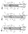
- FIG. 5 is a front cross section view of the combination tire gauge valve stem of the present invention while in an inert position.
- FIG. 6 is a front cross section view of the combination tire gauge valve stem of the present invention as shown being inflated.
- FIG. 7 is a front cross section view of the combination tire gauge valve stem of the present invention while under pressure.
- FIG. 1 illustrates a perspective view from above of the combination tire gauge valve stem 2 of the present invention as installed on a tire rim 3 having an upper valve portion 4 , a central gauge portion 6 and a lower rim-attaching portion 8 .
- the central gauge portion 6 is marked with a numeric scale 9 related to the calibration of the combination tire gauge valve stem 2 of the present invention.
- FIG. 2 illustrating a cross section view the upper valve portion 4 of the combination tire gauge valve stem 2 of the present invention depicting the form of the valve pin 7 centering guide 5 whereby there is provided a through passage of air beyond said centering guide 5 .
- FIG. 3 illustrates a front elevation view of the combination tire gauge valve stem 2 .
- the combination tire gauge valve stem 2 comprises; an upper valve portion 4 , a central gauge portion 6 and a lower rim attaching portion 8 .
- the central gauge portion 6 is marked with a numeric scale 9 related to the calibration of the combination tire gauge valve stem 2 of the present invention.
- FIG. 4 depicting a cross section view of the lower rim attaching portion 8 of the combination tire gauge valve stem 2 of the present invention illustrating material removed from the inner surface of the lower rim attaching portion 8 whereby the gauge indicator 20 loses its seal ability while in this position, allowing air passage beyond gauge indicator 20 .
- FIG. 5 depicting a cross section view of the combination tire gauge valve stem 2 of the present invention illustrating its position in an inert state.
- the combination tire gauge valve stem 2 is installed by inserting said stem 2 through the perforation provided in a conventional tire rim 3 ensuring that the rim sealing portion 11 is in contact with the inside of the rim 3 .
- a central gauge portion 6 comprising: a transparent cylindrical sleeve 15 adapted to be fixedly bonded to the lower rim attaching portion 8 by means of overlapped sections 22 permanently bonded together; a rubber piston-like gauge indicator 20 having an outside diameter equal to the inside diameter 24 of the transparent cylindrical sleeve 15 so as to form a longitudinally impermeable seal between gauge indicator 20 and the transparent cylindrical sleeve 15 , and a coil spring 21 located within the inner area of the transparent cylindrical sleeve 15 and frictionally attached to the gauge indicator 20 ; and an upper valve portion 4 having a metallic body adapted with a threaded upper portion 10 for securing of a conventional dust cap, a valve seat 31 having a plurality of arrayed perforations 26 allowing the through passage of air, a valve stem 7 adapted to pass through a centered perforation of the valve seat 31 , a valve seal 25 integrally attached to a valve pin 7 having a plurality of arraye
- the lower portion of the upper valve portion 4 is fixedly bonded to the upper portion of the transparent cylindrical sleeve 15 by means of overlapped sections 23 permanently bonded together.
- a relief vent 16 adapted to relieve the positive pressure created by the upward movement and negative pressure created by the downward movement of the gauge indicator 20 .
- FIG. 6 depicting a cross section view of the combination tire gauge valve stem 2 of the present invention illustrating its position during inflation.
- the valve stem 7 is depressed downwardly which in turn separates the valve seal 25 from the valve seat 31 allowing air to pass through both arrays of perforations 26 and 27 of the valve seat 31 and valve seal 25 .
- the valve seal 25 blocks the passage of air to the relief vent 16 as the valve stem 7 is depressed. This, in effect, exerts positive pressure on the top of the gauge indicator 20 , forcing said gauge indicator 20 toward and within the inner surface 34 of the lower rim attaching portion 8 which allows through flow of the air to the tire's chamber.
- FIG. 7 an illustration of the combination tire gauge valve stem 2 of the present invention illustrating its position under pressure.
- air pressure is built up within the tire's chamber and since the gauge indicator's 20 lower surface is in communication with said chamber's air, a force directly related to the amount of pressure within the tire's chamber is applied to the lower surface of the gauge indicator 20 thereby displacing said indicator 20 upwardly against the coil spring 21 within the transparent cylindrical sleeve 15 therefore placing the gauge indicator 20 in the corresponding position in the sleeve 15 corresponding to the markings 9 on the sleeve 15 .
- the gauge indicator 20 In daylight, the gauge indicator 20 would be visible through the transparent cylindrical sleeve 15 thus displaying the corresponding numerical reference relative to the tire's air pressure. In darkness, the luminescent properties of the gauge indicator 20 would make the numerical markings on the cylindrical sleeve 15 clearly visible. The greater the tire's air pressure, the further upwardly the gauge indicator 20 would be displaced.
Landscapes
- Engineering & Computer Science (AREA)
- Mechanical Engineering (AREA)
- Measuring Fluid Pressure (AREA)
- Check Valves (AREA)
Abstract
In an accessory device utilized to inflate and deflate conventional tubed or tubeless tire, and giving the user an indication of the amount of air pressure within the tire's chamber, the device of the present invention comprises; a flexible rim-attaching portion having a larger lower body portion than the rim perforation of a conventional tire and a central neck portion having an outside diameter equal or lesser than said rim perforation, a rigid central gauge portion having a transparent molded tube-like form imprinted with markings identifying the location of a moveable luminescent spring loaded rubber indicator adapted to travel longitudinally within said gauge portion, and an upper valve portion having a centered stem portion in direct communication with a valve seal where perforations in the valve seal are in misalignment with perforations in the valve seat. Therefore, when a tire is under pressure, the inner air pressure exerts positive pressure against the under side of the spring loaded lower valve seal which in turn, displaces the location of said seal, indicating the tire's air pressure.
Description
- The present invention relates to an accessory device utilized to inflate and deflate conventional tubed or tubeless tires while giving the user an indication of the amount of air pressure within the tire's chamber. The accessory device of the present invention comprises; a flexible rim-attaching portion having a larger lower body portion than the rim perforation of a conventional tire and a central neck portion having an outside diameter equal or lesser than said rim perforation, a rigid central gauge portion having a transparent molded tube-like form imprinted with markings identifying the location of a moveable luminescent spring loaded rubber indicator adapted to travel longitudinally within said gauge portion, and an upper valve portion having a centered stem portion in direct communication with a valve seal where perforations in the valve seal are in misalignment with perforations in the valve seat. Therefore, when a tire is under pressure, the inner air pressure exerts positive pressure against the under side of the spring loaded lower valve seal which in turn, displaces the location of said seal, indicating the tire's air pressure.
- For many years, inventors have attempted to adapt tire valve stems with an air pressure gauge. However, some of these inventions either did not work or failed to have the flexibility necessary for the abuse taken by valve stems. It is common for drivers to utilize an accessory tire gauge which requires the removal of the valve stem cover, thereby soiling the driver's fingers in doing so.
- Accordingly, it is desirable for drivers to be aware of their vehicle tires' air pressure at a glance, as it is desirable to have this function available in a manner that boasts safety.
- Furthermore, owners of these devices desire that the device be permanently installed from within the tire rim to the outside rather than from the outside so as to prevent the theft of these devices.
- The applicant is aware of several attempts in prior art to provide means of combining a valve stem and a tire gauge. For example, reference may be had to U.S. Pat. No. 1,423,447 of Noe, issued Jul. 18, 1922, which describes a rigid valve stem with a pressure gauge primarily designed to adapt to bicycles. However, this device fails to provide the required flexibility to resist breakage from the day to day abuse imposed onto the device.
- Another example of prior art may be had in referring to U.S. Pat. No. 3,230,968 of Struby, issued Jan. 25, 1966, which depicts a permanently installed valve having a color code indicator. However, this valve is very short, malting it difficult to view a reading. Additionally, its rigidity may pose a problem in abusive conditions. Furthermore, the telescopic portion is subjected to the elements of dirt and granular material which would therefore render the gauge inaccurate.
- Another example of prior art may be had in referring to U.S. Pat. No. 3,906,988 of Mottram, issued Sep. 23, 1975, which illustrates a rigid valve and gauge combination. Again, this valve is rigid and fails to have the ability to flex if stricken.
- While many prior art inventions have succeeded in providing vehicle operators with a combination air pressure gauge and valve stem, none have succeeded in offering flexibility with accuracy and durability in such valve stems.
- It is thus the object of the present invention to provide vehicle operators with a combination air pressure gauge and valve stem having flexibility, accuracy and durability all in one affordable unit.
- In one aspect of the invention, there is provided a daylight chargeable luminescent gauge indicator which illuminates in darkness.
- In another aspect of the invention, the valve/gauge combination may be calibrated to suit various ranges in pressure by altering the back-load spring and visual markings.
- In another aspect of the invention, the valve stem of the present invention may be adapted to form an integral part of a tubed tire by providing a flanged rubber extension to the base so as to allow fixed adhesion to a perforation in a tire tube.
- Accordingly, the accessory device of the present invention allows not only the gauging of pneumatic air pressure, but also provide structural flexibility of the unit while having a luminescent gauge indicator.
- The utility of this accessory device includes but is not limited to conventional pneumatic tires.
- These and other advantages of the invention will become apparent upon reading the following detailed description and upon referring to the drawings in which:
- FIG. 1 is a perspective view from above of the combination tire gauge valve stem of the present invention as installed on a tire rim.
- FIG. 2 is a cross section view from FIG. 5 of the upper valve portion of the present invention.
- FIG. 3 is a front elevation view of the combination tire gauge valve stem of the present invention.
- FIG. 4 is a cross section view from FIG. 6 of the rim-attaching portion of the present invention.
- FIG. 5 is a front cross section view of the combination tire gauge valve stem of the present invention while in an inert position.
- FIG. 6 is a front cross section view of the combination tire gauge valve stem of the present invention as shown being inflated.
- FIG. 7 is a front cross section view of the combination tire gauge valve stem of the present invention while under pressure.
- While the invention will be described in conjunction with illustrated embodiments, it will be understood that it is not intended to limit the invention to such embodiments. On the contrary, it is intended to cover all alternatives, modifications and equivalents as may be included within the spirit and scope of the invention as defined by the appended claims.
- In the following description, similar features in the drawings have been given similar reference numerals.
- Turning to FIG. 1, which illustrates a perspective view from above of the combination tire
gauge valve stem 2 of the present invention as installed on atire rim 3 having anupper valve portion 4, acentral gauge portion 6 and a lower rim-attachingportion 8. Thecentral gauge portion 6 is marked with anumeric scale 9 related to the calibration of the combination tiregauge valve stem 2 of the present invention. - Now turning to FIG. 2, illustrating a cross section view the
upper valve portion 4 of the combination tiregauge valve stem 2 of the present invention depicting the form of thevalve pin 7centering guide 5 whereby there is provided a through passage of air beyond saidcentering guide 5. - Turning to FIG. 3, which illustrates a front elevation view of the combination tire
gauge valve stem 2. The combination tiregauge valve stem 2 comprises; anupper valve portion 4, acentral gauge portion 6 and a lowerrim attaching portion 8. Thecentral gauge portion 6 is marked with anumeric scale 9 related to the calibration of the combination tiregauge valve stem 2 of the present invention. - Turning now to FIG. 4, depicting a cross section view of the lower
rim attaching portion 8 of the combination tiregauge valve stem 2 of the present invention illustrating material removed from the inner surface of the lowerrim attaching portion 8 whereby thegauge indicator 20 loses its seal ability while in this position, allowing air passage beyondgauge indicator 20. - In reference now to FIG. 5, depicting a cross section view of the combination tire
gauge valve stem 2 of the present invention illustrating its position in an inert state. The combination tiregauge valve stem 2 is installed by inserting saidstem 2 through the perforation provided in aconventional tire rim 3 ensuring that therim sealing portion 11 is in contact with the inside of therim 3. Beyond the lower rim-attachingportion 8 is provided acentral gauge portion 6 comprising: a transparentcylindrical sleeve 15 adapted to be fixedly bonded to the lowerrim attaching portion 8 by means of overlappedsections 22 permanently bonded together; a rubber piston-like gauge indicator 20 having an outside diameter equal to the inside diameter 24 of the transparentcylindrical sleeve 15 so as to form a longitudinally impermeable seal betweengauge indicator 20 and the transparentcylindrical sleeve 15, and acoil spring 21 located within the inner area of the transparentcylindrical sleeve 15 and frictionally attached to thegauge indicator 20; and anupper valve portion 4 having a metallic body adapted with a threadedupper portion 10 for securing of a conventional dust cap, avalve seat 31 having a plurality of arrayedperforations 26 allowing the through passage of air, avalve stem 7 adapted to pass through a centered perforation of thevalve seat 31, avalve seal 25 integrally attached to avalve pin 7 having a plurality of arrayedperforations 27 in misalignment with the perforations of thevalve seat 31, aflange stop 32 integral with thevalve stem 7 against which acoil spring 30 is placed between saidflange stop 32 andvalve seat 31 exerting an upward pressure of thevalve seal 25 against thevalve seat 31 thereby creating a positive impermeable seal. The lower portion of theupper valve portion 4 is fixedly bonded to the upper portion of the transparentcylindrical sleeve 15 by means of overlappedsections 23 permanently bonded together. Within theupper valve portion 4 of thedevice 2 of the present invention, there is provided arelief vent 16 adapted to relieve the positive pressure created by the upward movement and negative pressure created by the downward movement of thegauge indicator 20. - FIG. 6, depicting a cross section view of the combination tire
gauge valve stem 2 of the present invention illustrating its position during inflation. During inflation, thevalve stem 7 is depressed downwardly which in turn separates thevalve seal 25 from thevalve seat 31 allowing air to pass through both arrays ofperforations valve seat 31 andvalve seal 25. Thevalve seal 25 blocks the passage of air to therelief vent 16 as thevalve stem 7 is depressed. This, in effect, exerts positive pressure on the top of thegauge indicator 20, forcing saidgauge indicator 20 toward and within theinner surface 34 of the lowerrim attaching portion 8 which allows through flow of the air to the tire's chamber. - Turning now to FIG. 7, an illustration of the combination tire
gauge valve stem 2 of the present invention illustrating its position under pressure. In this state, once inflated, air pressure is built up within the tire's chamber and since the gauge indicator's 20 lower surface is in communication with said chamber's air, a force directly related to the amount of pressure within the tire's chamber is applied to the lower surface of thegauge indicator 20 thereby displacingsaid indicator 20 upwardly against thecoil spring 21 within the transparentcylindrical sleeve 15 therefore placing thegauge indicator 20 in the corresponding position in thesleeve 15 corresponding to themarkings 9 on thesleeve 15. In daylight, thegauge indicator 20 would be visible through the transparentcylindrical sleeve 15 thus displaying the corresponding numerical reference relative to the tire's air pressure. In darkness, the luminescent properties of thegauge indicator 20 would make the numerical markings on thecylindrical sleeve 15 clearly visible. The greater the tire's air pressure, the further upwardly thegauge indicator 20 would be displaced.
Claims (7)
1. A combination tire gauge valve stem comprising:
a. a tire valve stem adapted to allow the controlled intake and dispensing of air within a conventional tire's chamber,
b. a tire valve stem also adapted to gauge at a glance, the air pressure within the inner surface of a conventional tire's chamber,
2. The combination tire gauge valve stem of claim 1 wherein said gauge means are attained by a spring loaded piston-like gauge indicator counteracting the tire's air pressure visible through a transparent central portion of said stem.
3. The combination tire gauge valve stem of claim 2 wherein the piston-like gauge indicator is molded with a semi-flexible luminescent material having daylight recharging properties.
4. The combination tire gauge valve stem of claim 1 wherein the generally central region of the stem is transparent and is adapted with numeric markings in calibration with the tire's pressure range.
5. The combination tire gauge valve stem of claim 1 wherein the lower rim attaching portion is formed so that the inside diameter of the upper portion of said rim attaching portion is adapted with lengthwise indentations so as to allow the passage of air around the gauge indicator for inflation of tire chamber.
6. The combination tire gauge valve stem of claim 1 wherein the upper valve portion consists of a valve seat and a valve seal each having a plurality of perforations therethrough in misalignment whereby when valve seal is seated onto valve seat, the flow of air is restricted and when the valve seal is separated from valve seat, the flow of air is made possible.
7. The combination tire gauge valve stem of claim 1 wherein the lower rim-attaching portion is adapted with a plurality of lengthwise indentations within the inner surface of said rim-attaching portion so as to allow through-passage of air when gauge indicator is displaced to that area.
Priority Applications (1)
| Application Number | Priority Date | Filing Date | Title |
|---|---|---|---|
| US10/119,007 US20030192371A1 (en) | 2002-04-10 | 2002-04-10 | Combination tire gauge valve stem |
Applications Claiming Priority (1)
| Application Number | Priority Date | Filing Date | Title |
|---|---|---|---|
| US10/119,007 US20030192371A1 (en) | 2002-04-10 | 2002-04-10 | Combination tire gauge valve stem |
Publications (1)
| Publication Number | Publication Date |
|---|---|
| US20030192371A1 true US20030192371A1 (en) | 2003-10-16 |
Family
ID=28789900
Family Applications (1)
| Application Number | Title | Priority Date | Filing Date |
|---|---|---|---|
| US10/119,007 Abandoned US20030192371A1 (en) | 2002-04-10 | 2002-04-10 | Combination tire gauge valve stem |
Country Status (1)
| Country | Link |
|---|---|
| US (1) | US20030192371A1 (en) |
Cited By (4)
| Publication number | Priority date | Publication date | Assignee | Title |
|---|---|---|---|---|
| US20080110252A1 (en) * | 2006-10-28 | 2008-05-15 | Cook Ronald D | Tire filler with pressure indicator |
| USD611373S1 (en) * | 2007-12-28 | 2010-03-09 | Stotz Feinmesstechnik Gmbh | Air gauge |
| US8151127B2 (en) | 2000-07-26 | 2012-04-03 | Bridgestone Americas Tire Operations, Llc | System for conserving battery life in a battery operated device |
| US8266465B2 (en) | 2000-07-26 | 2012-09-11 | Bridgestone Americas Tire Operation, LLC | System for conserving battery life in a battery operated device |
-
2002
- 2002-04-10 US US10/119,007 patent/US20030192371A1/en not_active Abandoned
Cited By (6)
| Publication number | Priority date | Publication date | Assignee | Title |
|---|---|---|---|---|
| US8151127B2 (en) | 2000-07-26 | 2012-04-03 | Bridgestone Americas Tire Operations, Llc | System for conserving battery life in a battery operated device |
| US8266465B2 (en) | 2000-07-26 | 2012-09-11 | Bridgestone Americas Tire Operation, LLC | System for conserving battery life in a battery operated device |
| US20080110252A1 (en) * | 2006-10-28 | 2008-05-15 | Cook Ronald D | Tire filler with pressure indicator |
| US7373811B1 (en) * | 2006-10-28 | 2008-05-20 | Cook Ronald D | Tire filler with pressure indicator |
| USD611373S1 (en) * | 2007-12-28 | 2010-03-09 | Stotz Feinmesstechnik Gmbh | Air gauge |
| USD623971S1 (en) * | 2007-12-28 | 2010-09-21 | Stotz Feinmesstechnik Gmbh | Air gauge |
Similar Documents
| Publication | Publication Date | Title |
|---|---|---|
| US4072048A (en) | Indicating apparatus for measuring the pressure of a fluid within a container | |
| US5365967A (en) | Safety tire valve | |
| US3230968A (en) | Combination valve and gauge | |
| US5503012A (en) | Tire pressure monitoring device | |
| US3906988A (en) | Combined valve and pressure indicator for pneumatic tires | |
| US4464929A (en) | Tire cap pressure gauge | |
| US4901747A (en) | Tire inflation valve with pressure indicator | |
| GB2069139A (en) | Pressure indicators for pneumatic tyres | |
| US5027848A (en) | Pressure indicating valve stem | |
| US6247513B1 (en) | Pressure indicating tire inflation valve | |
| US20030192371A1 (en) | Combination tire gauge valve stem | |
| US4384543A (en) | Combined underinflation indicator and relief valve | |
| US10828946B2 (en) | Pressure measuring cap | |
| US6119714A (en) | Valve cap with pressure indicating label | |
| US5325886A (en) | Inflation and pressure indicator apparatus for tires | |
| US6978670B2 (en) | Tire valve-gauge combination | |
| US6125694A (en) | Circumferentially disposed automatic whistling tire pressure gauge warning and limiting assembly | |
| US5641902A (en) | Tire valve cap pressure gauge | |
| US4262529A (en) | Pressure sensitive indicating device | |
| US6296010B1 (en) | Automatic shut-off air pressure valve for tires | |
| EP0383757B1 (en) | Pressure indicating valve stem | |
| USRE29116E (en) | Pressure gauge | |
| CA2540920C (en) | Tire valve-gauge combination | |
| US20030144096A1 (en) | Inflatable device | |
| US3792677A (en) | Pressure indicator for pneumatic tire wheels |
Legal Events
| Date | Code | Title | Description |
|---|---|---|---|
| STCB | Information on status: application discontinuation |
Free format text: ABANDONED -- FAILURE TO RESPOND TO AN OFFICE ACTION |