US20030190988A1 - High performance intermediate servo assembly - Google Patents
High performance intermediate servo assembly Download PDFInfo
- Publication number
- US20030190988A1 US20030190988A1 US10/408,054 US40805403A US2003190988A1 US 20030190988 A1 US20030190988 A1 US 20030190988A1 US 40805403 A US40805403 A US 40805403A US 2003190988 A1 US2003190988 A1 US 2003190988A1
- Authority
- US
- United States
- Prior art keywords
- servo
- piston
- high performance
- servo piston
- accumulator
- Prior art date
- Legal status (The legal status is an assumption and is not a legal conclusion. Google has not performed a legal analysis and makes no representation as to the accuracy of the status listed.)
- Granted
Links
- 239000012530 fluid Substances 0.000 claims abstract description 32
- 230000005540 biological transmission Effects 0.000 claims description 31
- 230000004323 axial length Effects 0.000 claims description 9
- 230000013011 mating Effects 0.000 claims description 9
- 125000006850 spacer group Chemical group 0.000 claims description 8
- 238000000034 method Methods 0.000 claims description 6
- 238000004519 manufacturing process Methods 0.000 claims description 5
- 238000003754 machining Methods 0.000 claims description 4
- 238000007789 sealing Methods 0.000 claims description 4
- 230000006872 improvement Effects 0.000 claims description 2
- 238000003780 insertion Methods 0.000 claims 2
- 230000037431 insertion Effects 0.000 claims 2
- 239000004809 Teflon Substances 0.000 description 2
- 229920006362 Teflon® Polymers 0.000 description 2
- 230000002159 abnormal effect Effects 0.000 description 2
- 230000008901 benefit Effects 0.000 description 2
- 230000008859 change Effects 0.000 description 2
- 238000005516 engineering process Methods 0.000 description 2
- 239000000463 material Substances 0.000 description 2
- 230000007246 mechanism Effects 0.000 description 2
- 230000035939 shock Effects 0.000 description 2
- XAGFODPZIPBFFR-UHFFFAOYSA-N aluminium Chemical compound [Al] XAGFODPZIPBFFR-UHFFFAOYSA-N 0.000 description 1
- 229910052782 aluminium Inorganic materials 0.000 description 1
- 230000009286 beneficial effect Effects 0.000 description 1
- 238000005266 casting Methods 0.000 description 1
- 230000005465 channeling Effects 0.000 description 1
- 230000003247 decreasing effect Effects 0.000 description 1
- NBVXSUQYWXRMNV-UHFFFAOYSA-N fluoromethane Chemical compound FC NBVXSUQYWXRMNV-UHFFFAOYSA-N 0.000 description 1
- 238000009434 installation Methods 0.000 description 1
- 239000000314 lubricant Substances 0.000 description 1
- 230000004048 modification Effects 0.000 description 1
- 238000012986 modification Methods 0.000 description 1
- 229920001343 polytetrafluoroethylene Polymers 0.000 description 1
- 239000004810 polytetrafluoroethylene Substances 0.000 description 1
- 238000004904 shortening Methods 0.000 description 1
- 238000006467 substitution reaction Methods 0.000 description 1
- 238000007514 turning Methods 0.000 description 1
Images


Classifications
-
- F—MECHANICAL ENGINEERING; LIGHTING; HEATING; WEAPONS; BLASTING
- F16—ENGINEERING ELEMENTS AND UNITS; GENERAL MEASURES FOR PRODUCING AND MAINTAINING EFFECTIVE FUNCTIONING OF MACHINES OR INSTALLATIONS; THERMAL INSULATION IN GENERAL
- F16D—COUPLINGS FOR TRANSMITTING ROTATION; CLUTCHES; BRAKES
- F16D49/00—Brakes with a braking member co-operating with the periphery of a drum, wheel-rim, or the like
- F16D49/08—Brakes with a braking member co-operating with the periphery of a drum, wheel-rim, or the like shaped as an encircling band extending over approximately 360 degrees
-
- F—MECHANICAL ENGINEERING; LIGHTING; HEATING; WEAPONS; BLASTING
- F16—ENGINEERING ELEMENTS AND UNITS; GENERAL MEASURES FOR PRODUCING AND MAINTAINING EFFECTIVE FUNCTIONING OF MACHINES OR INSTALLATIONS; THERMAL INSULATION IN GENERAL
- F16D—COUPLINGS FOR TRANSMITTING ROTATION; CLUTCHES; BRAKES
- F16D49/00—Brakes with a braking member co-operating with the periphery of a drum, wheel-rim, or the like
Definitions
- the present invention relates to the field of automatic transmissions and, more particularly, to a high performance intermediate servo assembly for use in General Motors 200 4R transmissions (hereinafter “GM transmissions”).
- GM transmissions General Motors 200 4R transmissions
- ATF automatic transmission fluid
- the intermediate servo assembly is applied in 2 nd gear and is used as an accumulator in 3 rd gear.
- An accumulator is a spring-loaded device that absorbs a certain amount of apply fluid pressure to cushion the application of a clutch band against fluid shock to control shift feel and to prevent damage to these components.
- U.S. Pat. No. 4,601,233 to Sugano discloses a hydraulic servo device with a built-in accumulator comprising a servo piston fit in a servo cylinder and connected via a stem to a band brake, an accumulator piston, and an accumulator piston spring biases the accumulator piston toward the servo piston.
- a servo release pressure acts on a pressure acting area
- a servo apply pressure acts on a pressure acting area
- an accumulator pressure acts on a pressure acting area in the operation thereof.
- U.S. Pat. No. 4,388,986 to Umezawa discloses a speed change control for an automatic transmission having a planetary gear mechanism and a brake band for altering the transmission ratio.
- the system comprises a servo-piston, a piston rod secured to the servo-piston and to the brake band, and an accumulator piston axially slidably disposed in the bore of the servo-piston.
- U.S. Pat. No. 5,944,627 to Darling-Owen and also owned by the applicant discloses a replacement servo mechanism for applying a band in an automatic transmission wherein the servo assembly includes two servo piston members, a major piston member and a minor piston member, to which an apply pin is connected.
- the present invention is a high performance intermediate servo assembly wherein the servo piston has been modified to provide at least a 17% increase in surface apply area and a corresponding increase in hydraulic fluid delivered to the 2 nd gear clutch band, which it actuates to obtain 2 nd gear. This is accomplished by increasing the diameter of the servo piston and its mating cover while maintaining its overall dimensions to fit the OEM transmission case.
- the present servo piston is reconfigured to an overall length equivalent to the assembled stack-up dimensions of the original equipment servo piston, accumulator, accumulator spring, and spring retainer components and integrates the critical working surfaces (i.e. spring seat, axial travel stop) thereof to retain proper function.
- Such original equipment components have been eliminated to simplify the intermediate servo piston's operation since shift feel is not a particular concern in this high performance application.
- the O-ring seals on the OEM servo piston are replaced by high performance seals such as quad-lobed seals to ensure the hydraulic integrity of the intermediate servo under the increased fluid pressure generated by the present high performance servo piston.
- FIG. 1 is an exploded view of an intermediate servo for the GM transmissions labeled Prior Art
- FIG. 2 is a perspective view of an intermediate servo assembly shown in its functional position engaging a clutch band labeled Prior Art;
- FIG. 3 is an exploded elevational view of the intermediate servo including components of an aftermarket kit labeled Prior Art;
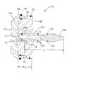
- FIG. 4 is a cross-sectional view of the intermediate servo of the present invention in the release position.
- FIG. 5 is a cross-sectional view of the intermediate servo of the present invention in the apply position.
- FIG. 1 there is shown an exploded view of the OEM intermediate servo assembly, indicated generally at 100 .
- the OEM servo assembly 100 is comprised of a servo cover 105 , O-ring 106 , retaining ring 107 , piston 110 , inner lip seal 111 , outer lip seal 112 , accumulator piston 115 , Teflon seal 117 , accumulator spring 118 , retaining clip 119 , spring retainer 120 , band apply pin 122 , cushion spring 124 , and O-rings 125 arranged coaxially for installation in the transmission case 135 (FIG. 2).
- the OEM intermediate servo assembly 100 functions to apply the intermediate clutch band 130 in 2 nd gear as shown in FIG. 2 and is used as an accumulator in 3 rd gear.
- An accumulator is a spring-loaded device that absorbs a certain amount of apply fluid pressure to cushion the application of a clutch band against fluid shock and also improves shift feel.
- the intermediate band 130 is applied by servo 100 .
- the intermediate band 130 is compressed around the direct clutch drum (not shown) with its distal end 130 a mechanically anchored to the transmission case 135 .
- the other end of the intermediate band 130 is hydraulically actuated by the intermediate servo 100 .
- the intermediate band 130 is applied, the rotation of the direct clutch drum (not shown) is prevented, which places the transaxle in 2 nd gear.
- the servo piston 110 is actuated by 2 nd gear clutch fluid pressure at 132 which is delivered via an oil passage 27 (FIG. 4) in the apply pin 122 and acts on the apply side of piston 110 .
- the apply rate of the intermediate band 130 is controlled by the 2 nd gear fluid compressing the cushion spring 124 .
- the band apply pin 122 is forced into the band 130 .
- the band 130 is compressed around the direct clutch housing or drum (not shown) until the drum is held stationary to obtain 2 nd gear.
- the OEM intermediate servo 100 releases in 3 rd gear by channeling 3 rd clutch fluid to the 3 rd accumulator exhaust valve (not shown).
- the force of the cushion spring 124 and the 3 rd gear clutch fluid will overcome the pressure of the 2 nd gear clutch fluid and move the piston 110 to release the band 130 .
- the return stroke of the servo piston 110 to release the band 130 acts as an accumulator for 3 rd gear by absorbing some 3 rd gear clutch fluid. This allows the band 130 to release and the direct clutch to apply at a controlled rate for a smooth 2-3 shift.
- the user of this kit is instructed by the manufacturer to remove the Teflon seal 117 from the accumulator piston 115 to disable its function. All of the remaining OEM components except for spring 118 (i.e. accumulator piston 115 , clip 119 , spring retainer 120 , apply pin 122 , and cushion spring 124 ) are effectively used as spacers during reassembly. However, reassembly of the modified intermediate servo 100 ′ in such manner with the spring 118 omitted creates mismatched part surfaces and the potential for noise, abnormal wear, and inaccurate operation.
- spring 118 i.e. accumulator piston 115 , clip 119 , spring retainer 120 , apply pin 122 , and cushion spring 124
- FIG. 4 there is shown therein an intermediate servo assembly in accordance with the present invention, indicated generally at 10 .
- the present intermediate servo assembly 10 is comprised of a modified servo cover 15 , a modified servo piston 20 , and a modified pin 29 , which are configured as shown.
- the present servo assembly 10 utilizes a heavier gauge return spring 24 having a spring rate in the range of 150 to 155 pounds, which differs significantly from the OEM cushion spring 124 .
- the return spring 24 is seated on at least one washer or spacer 25 as shown.
- the modified pin 29 is provided with seals 125 and seal 126 at locations designed to prevent leakage of the increased hydraulic pressure generated by the servo piston 20 from the piston chamber 50 .
- the modified pin 29 is also provided with structures comprising length-adjusting means including, but not limited to, the following structures.
- the thickness and/or number of spacers 25 may be varied to adjust the effective overall length “L” of the pin 29 and the operating characteristics of the band 130 .
- the band 130 can be brought into closer proximity with the clutch drum (not shown) by increasing length “L” thereby reducing the actuating stroke and time required to apply the clutch.
- the length-adjusting means further include a plurality of tapered segments 28 delineated by circumferential undercut markings 29 a ′ formed in the tip 29 a of the pin 29 .
- the distal segment 28 of pin 29 is removed by machining (e.g. grinding) to shorten the overall length of pin 29 .
- the application of the clutch can also be adjusted by shortening of the tip 29 a to increase the actuating stroke and/or delay the time required to apply the clutch.
- the modified servo cover 15 and servo piston 20 are fabricated from aluminum bar stock, castings, or extruded stock.
- the inside diameter (I.D.) of the piston bore 15 b has been substantially increased over the OEM and aftermarket designs to generate an increase in fluid capacity and, thus, an increase in holding power of the band 130 and the direct clutch.
- the servo cover 15 is provided with a tool groove 15 a, which facilitates removal of the cover 15 from the transmission case 135 for service/overhaul purposes.
- the servo cover 15 is provided with an O-ring seal 116 substantially the same as the OEM version for sealing within the mating bore 150 (FIG. 2) of the transmission case 135 .
- the axial length “AL” of the servo piston 20 has been increased to correspond to the sum total of the assembled stack-up dimension of the OEM piston 110 , the accumulator 115 , accumulator spring 118 , and spring retainer 120 while integrating the critical working surfaces thereof. More particularly, the spring retainer 120 , which functions as a seat for spring 124 in the OEM design is effectively built into the present piston 20 as at tapered counterbore 21 . Thus, it will be understood that all of the aforementioned OEM components are unnecessary in the present design and may be discarded when the intermediate servo assembly 10 is retrofitted to the GM transmissions.
- lip seals 111 , 112 have been replaced by a seal having a multi-lobed configuration known as a quad-lobed seal 30 .
- Quad lobed seals are very reliable because they have twice the sealing surfaces as standard round O-rings.
- the quad-lobed seals 30 are preferably made from fluorocarbon material (i.e. PTFE), which provides improved heat resistance.
- PTFE fluorocarbon material
- the OEM intermediate servo is removed from the transmission case and discarded.
- a modified apply pin 29 having a shortened axial length is fitted with new seals 125 , at least one washer 25 is mounted in position, and the apply pin 29 is pressed into the servo piston 20 as shown in FIG. 4.
- the quad-lobed seals 30 are installed in the appropriate grooves 32 formed in the outside diameters (O.D.) of the servo piston 20 with a suitable lubricant and the piston 20 is engaged in the piston bore 15 b of the piston cover 15 as shown.
- the return spring 24 is placed in position and the servo assembly 10 is installed in the mating bore 150 (FIG. 2) of the transmission case 135 such that the tapered tip 29 a of the apply pin 29 engages a receptacle 123 on the moveable end 130 b of band 130 .
- the present invention provides a high performance intermediate servo assembly for use with GM transmissions that produces at least a 17% increase in surface apply area of the servo piston and a corresponding increase in hydraulic fluid delivered to the 2 nd gear clutch band, which it actuates to obtain 2 nd gear.
- the present intermediate servo assembly reduces the number of component parts required and improves the performance of the intermediate servo in comparison to aftermarket replacement kits.
Landscapes
- Engineering & Computer Science (AREA)
- General Engineering & Computer Science (AREA)
- Mechanical Engineering (AREA)
- Hydraulic Clutches, Magnetic Clutches, Fluid Clutches, And Fluid Joints (AREA)
- Gear-Shifting Mechanisms (AREA)
Abstract
Description
- This application claims the benefit under 35 U.S.C.§ 119(e) of U.S. Provisional Patent Application No. 60/369,520 filed Apr. 4, 2002, entitled High Performance Intermediate Servo Assembly.
- The present invention relates to the field of automatic transmissions and, more particularly, to a high performance intermediate servo assembly for use in General Motors 200 4R transmissions (hereinafter “GM transmissions”).
- Automatic transmission systems of the prior art have a hydraulic circuit sub-system which includes at least a hydraulic pump, a valve body having fluid conducting passages or circuits, input and exhaust ports formed within the fluid circuits, and a plurality of valves comprised of generally cylindrical pistons having control lands formed thereon, which alternately open and close the ports to the fluid circuits to regulate the flow and pressure of automatic transmission fluid (hereinafter “ATF”) to hydraulically actuate various components of the transmission. It will be understood that in describing hydraulic circuits, ATF usually changes names when it passes through an orifice or control valve in a specific fluid circuit.
- In the GM transmissions the intermediate servo assembly is applied in 2 nd gear and is used as an accumulator in 3rd gear. An accumulator is a spring-loaded device that absorbs a certain amount of apply fluid pressure to cushion the application of a clutch band against fluid shock to control shift feel and to prevent damage to these components.
- In high performance applications it is desirable to increase the hydraulic fluid capacity and fluid pressure generated by the intermediate servo assembly to increase the holding capacity of the clutch band under high load conditions.
- There are known prior art patents in the field and their discussion follows. U.S. Pat. No. 4,601,233 to Sugano discloses a hydraulic servo device with a built-in accumulator comprising a servo piston fit in a servo cylinder and connected via a stem to a band brake, an accumulator piston, and an accumulator piston spring biases the accumulator piston toward the servo piston. A servo release pressure acts on a pressure acting area, a servo apply pressure acts on a pressure acting area, and an accumulator pressure acts on a pressure acting area in the operation thereof.
- Another example of this type of servo is shown in U.S. Pat. No. 4,787,494 to Ogasawara et al., which discloses a hydraulic operating unit for a friction-engaging band of a transmission that permits the introduction of a low-pressure working fluid to allow forcible disengagement of the hydraulic operation unit to work against the fluid, which would normally urge the unit into engagement.
- U.S. Pat. No. 4,388,986 to Umezawa discloses a speed change control for an automatic transmission having a planetary gear mechanism and a brake band for altering the transmission ratio. The system comprises a servo-piston, a piston rod secured to the servo-piston and to the brake band, and an accumulator piston axially slidably disposed in the bore of the servo-piston.
- U.S. Pat. No. 5,944,627 to Darling-Owen and also owned by the applicant discloses a replacement servo mechanism for applying a band in an automatic transmission wherein the servo assembly includes two servo piston members, a major piston member and a minor piston member, to which an apply pin is connected.
- It is also known in the prior art to adapt the original equipment manufacture (hereinafter “OEM”) intermediate servo for high performance applications by providing an aftermarket intermediate servo kit. A commercially available kit of the type marketed by Shift Technology Products, a division of Superior Transmission Parts, Inc., Tallahassee, Fla., has been designed for this purpose (FIG. 3) and is described hereinafter in further detail. For the high performance application, the user of this prior art kit is instructed by the manufacturer to disable the function of the integrated accumulator. All of the remaining OEM components are effectively used as spacers in reassembly. However, reassembly of the intermediate servo in such a manner creates mismatched part surfaces causing inaccurate operation and the potential for noise and abnormal wear.
- While these devices fulfill their respective, particular objectives and requirements, the aforementioned patents do not disclose the high performance intermediate servo assembly of the present invention, which substantially departs from the conventional concepts and designs of the prior art.
- Accordingly, the present invention is a high performance intermediate servo assembly wherein the servo piston has been modified to provide at least a 17% increase in surface apply area and a corresponding increase in hydraulic fluid delivered to the 2 nd gear clutch band, which it actuates to obtain 2nd gear. This is accomplished by increasing the diameter of the servo piston and its mating cover while maintaining its overall dimensions to fit the OEM transmission case.
- In addition, the present servo piston is reconfigured to an overall length equivalent to the assembled stack-up dimensions of the original equipment servo piston, accumulator, accumulator spring, and spring retainer components and integrates the critical working surfaces (i.e. spring seat, axial travel stop) thereof to retain proper function. Such original equipment components have been eliminated to simplify the intermediate servo piston's operation since shift feel is not a particular concern in this high performance application. Further, the O-ring seals on the OEM servo piston are replaced by high performance seals such as quad-lobed seals to ensure the hydraulic integrity of the intermediate servo under the increased fluid pressure generated by the present high performance servo piston.
- There has thus been outlined, rather broadly, the important features of the present invention in order that the detailed description thereof that follows may be better understood, and in order that the present contribution to the art may be better appreciated. There are additional features of the invention that will be described hereinafter and which will form the subject matter of the claims appended hereto.
- The novel features of the present invention are set forth in the appended claims. The invention itself, however, as well as other features and advantages thereof will be best understood by reference to the following detailed description of an illustrative embodiment when read in conjunction with the accompanying figures, wherein:
- FIG. 1 is an exploded view of an intermediate servo for the GM transmissions labeled Prior Art;
- FIG. 2 is a perspective view of an intermediate servo assembly shown in its functional position engaging a clutch band labeled Prior Art;
- FIG. 3 is an exploded elevational view of the intermediate servo including components of an aftermarket kit labeled Prior Art;
- FIG. 4 is a cross-sectional view of the intermediate servo of the present invention in the release position; and
- FIG. 5 is a cross-sectional view of the intermediate servo of the present invention in the apply position.
- Prior to describing the present invention in detail it may be beneficial to briefly review the structure and function of an intermediate servo assembly of the GM transmissions. With reference to FIG. 1 there is shown an exploded view of the OEM intermediate servo assembly, indicated generally at 100. The
OEM servo assembly 100 is comprised of aservo cover 105, O-ring 106,retaining ring 107,piston 110,inner lip seal 111,outer lip seal 112,accumulator piston 115, Teflonseal 117,accumulator spring 118,retaining clip 119,spring retainer 120, band applypin 122,cushion spring 124, and O-rings 125 arranged coaxially for installation in the transmission case 135 (FIG. 2). - The OEM
intermediate servo assembly 100 functions to apply theintermediate clutch band 130 in 2nd gear as shown in FIG. 2 and is used as an accumulator in 3rd gear. An accumulator is a spring-loaded device that absorbs a certain amount of apply fluid pressure to cushion the application of a clutch band against fluid shock and also improves shift feel. - In 2 nd gear the
intermediate band 130 is applied byservo 100. Theintermediate band 130 is compressed around the direct clutch drum (not shown) with itsdistal end 130 a mechanically anchored to thetransmission case 135. The other end of theintermediate band 130 is hydraulically actuated by theintermediate servo 100. When theintermediate band 130 is applied, the rotation of the direct clutch drum (not shown) is prevented, which places the transaxle in 2nd gear. - In 2 nd gear the
servo piston 110 is actuated by 2nd gear clutch fluid pressure at 132 which is delivered via an oil passage 27 (FIG. 4) in the applypin 122 and acts on the apply side ofpiston 110. The apply rate of theintermediate band 130 is controlled by the 2nd gear fluid compressing thecushion spring 124. By applying theservo piston 110 the band applypin 122 is forced into theband 130. Thus, theband 130 is compressed around the direct clutch housing or drum (not shown) until the drum is held stationary to obtain 2nd gear. - The OEM
intermediate servo 100 releases in 3rd gear by channeling 3rd clutch fluid to the 3rd accumulator exhaust valve (not shown). The force of thecushion spring 124 and the 3rd gear clutch fluid will overcome the pressure of the 2nd gear clutch fluid and move thepiston 110 to release theband 130. The return stroke of theservo piston 110 to release theband 130 acts as an accumulator for 3rd gear by absorbing some 3rd gear clutch fluid. This allows theband 130 to release and the direct clutch to apply at a controlled rate for a smooth 2-3 shift. - It is known in the prior art to adapt the OEM
intermediate servo 100 for high performance applications by providing an aftermarket intermediate servo kit. A commercially available kit of the type marketed by Shift Technology Products, a division of Superior Transmission Parts, Inc., Tallahassee, Fla., has been designed for this purpose. As shown in FIG. 3 this kit produces a modifiedintermediate servo 100′ including aservo cover 105′ and aservo piston 110′, which are machined oversize to provide additional fluid volume.New lip seals - For the high performance application, the user of this kit is instructed by the manufacturer to remove the Teflon
seal 117 from theaccumulator piston 115 to disable its function. All of the remaining OEM components except for spring 118 (i.e. accumulatorpiston 115,clip 119,spring retainer 120, applypin 122, and cushion spring 124) are effectively used as spacers during reassembly. However, reassembly of the modifiedintermediate servo 100′ in such manner with thespring 118 omitted creates mismatched part surfaces and the potential for noise, abnormal wear, and inaccurate operation. - Accordingly, the present high performance, intermediate servo assembly has been developed to resolve these problems and will now be described. With reference to FIG. 4 there is shown therein an intermediate servo assembly in accordance with the present invention, indicated generally at 10. The present
intermediate servo assembly 10 is comprised of a modifiedservo cover 15, a modifiedservo piston 20, and a modifiedpin 29, which are configured as shown. Thepresent servo assembly 10 utilizes a heaviergauge return spring 24 having a spring rate in the range of 150 to 155 pounds, which differs significantly from theOEM cushion spring 124. Thereturn spring 24 is seated on at least one washer orspacer 25 as shown. - The modified
pin 29 is provided withseals 125 and seal 126 at locations designed to prevent leakage of the increased hydraulic pressure generated by theservo piston 20 from thepiston chamber 50. The modifiedpin 29 is also provided with structures comprising length-adjusting means including, but not limited to, the following structures. In the present design the thickness and/or number ofspacers 25 may be varied to adjust the effective overall length “L” of thepin 29 and the operating characteristics of theband 130. Thus, theband 130 can be brought into closer proximity with the clutch drum (not shown) by increasing length “L” thereby reducing the actuating stroke and time required to apply the clutch. - In addition, the length-adjusting means further include a plurality of tapered
segments 28 delineated by circumferentialundercut markings 29 a′ formed in thetip 29 a of thepin 29. Utilizing a method of the present invention thedistal segment 28 ofpin 29 is removed by machining (e.g. grinding) to shorten the overall length ofpin 29. Thus, the application of the clutch can also be adjusted by shortening of thetip 29 a to increase the actuating stroke and/or delay the time required to apply the clutch. - Of course, such length adjustments and the resultant clutch performance can be fine tuned by varying the thickness and/or number of
spacers 25 as described hereinabove in combination with grinding thetip 29 a of thepin 29 to provide optimal shift performance. - In the preferred embodiment the modified
servo cover 15 andservo piston 20 are fabricated from aluminum bar stock, castings, or extruded stock. The inside diameter (I.D.) of the piston bore 15 b has been substantially increased over the OEM and aftermarket designs to generate an increase in fluid capacity and, thus, an increase in holding power of theband 130 and the direct clutch. - As shown in FIG. 4 the
servo cover 15 is provided with atool groove 15 a, which facilitates removal of thecover 15 from thetransmission case 135 for service/overhaul purposes. Theservo cover 15 is provided with an O-ring seal 116 substantially the same as the OEM version for sealing within the mating bore 150 (FIG. 2) of thetransmission case 135. - Still referring to FIG. 4 the axial length “AL” of the
servo piston 20 has been increased to correspond to the sum total of the assembled stack-up dimension of theOEM piston 110, theaccumulator 115,accumulator spring 118, andspring retainer 120 while integrating the critical working surfaces thereof. More particularly, thespring retainer 120, which functions as a seat forspring 124 in the OEM design is effectively built into thepresent piston 20 as attapered counterbore 21. Thus, it will be understood that all of the aforementioned OEM components are unnecessary in the present design and may be discarded when theintermediate servo assembly 10 is retrofitted to the GM transmissions. - Further, it can be seen in FIG. 4 that lip seals 111, 112 have been replaced by a seal having a multi-lobed configuration known as a quad-
lobed seal 30. Quad lobed seals are very reliable because they have twice the sealing surfaces as standard round O-rings. In the present invention the quad-lobed seals 30 are preferably made from fluorocarbon material (i.e. PTFE), which provides improved heat resistance. Thus, the presentintermediate servo 10 is capable of generating and maintaining increased hydraulic fluid pressure and holding power to the direct clutch. - In order to install the present
intermediate servo assembly 10, the OEM intermediate servo is removed from the transmission case and discarded. Next, a modified applypin 29 having a shortened axial length is fitted withnew seals 125, at least onewasher 25 is mounted in position, and the applypin 29 is pressed into theservo piston 20 as shown in FIG. 4. Next, the quad-lobed seals 30 are installed in the appropriate grooves 32 formed in the outside diameters (O.D.) of theservo piston 20 with a suitable lubricant and thepiston 20 is engaged in the piston bore 15 b of thepiston cover 15 as shown. Thereafter, thereturn spring 24 is placed in position and theservo assembly 10 is installed in the mating bore 150 (FIG. 2) of thetransmission case 135 such that the taperedtip 29 a of the applypin 29 engages areceptacle 123 on the moveable end 130 b ofband 130. - In operation 2 nd gear clutch fluid pressure is delivered to the
piston chamber 50 viaoil passage 27 in the applypin 29 and acts on the apply side ofpiston 20 as shown in FIG. 5. As thepiston chamber 50 is filled with fluid under pressure, thepiston 20 is stroked (i.e. to the right in FIG. 5) against the force ofspring 24. Actuation of theservo piston 10 forces the applypin 29 into theband 130, which compresses around the direct clutch drum to prevent it from turning to obtain 2nd gear. When clutch fluid pressure is released, theservo piston 20 returns to the position shown in FIG. 4 and the clutch is released. - It will be noted that the return stroke of the
present servo piston 20 is stopped by contact with the end face ofcover 15 c against ashoulder 20 a formed about the circumference of piston 20 (FIG. 5). This represents an improvement in operating control over the prior art design wherein theproximal end 122 a ofpin 122 bottoms out on the inside ofcover 105′ to halt the return stroke of thepiston 110′. The present design also permits the combined axial length of theservo piston 20 and cover 15 to be decreased significantly, which uses less material and reduces manufacturing costs. - Thus, it can be seen that the present invention provides a high performance intermediate servo assembly for use with GM transmissions that produces at least a 17% increase in surface apply area of the servo piston and a corresponding increase in hydraulic fluid delivered to the 2 nd gear clutch band, which it actuates to obtain 2nd gear. The present intermediate servo assembly reduces the number of component parts required and improves the performance of the intermediate servo in comparison to aftermarket replacement kits.
- Although not specifically illustrated in the drawings, it should be understood that additional equipment and structural components will be provided as necessary and that all of the components described above are arranged and supported in an appropriate fashion to form a complete and operative high performance intermediate servo incorporating features of the present invention.
- Moreover, although illustrative embodiments of the invention have been described, a latitude of modification, change, and substitution is intended in the foregoing disclosure, and in certain instances some features of the invention will be employed without a corresponding use of other features. Accordingly, it is appropriate that the appended claims be construed broadly and in a manner consistent with the scope of invention.
Claims (16)
Priority Applications (2)
| Application Number | Priority Date | Filing Date | Title |
|---|---|---|---|
| US10/408,054 US6907974B2 (en) | 2002-04-04 | 2003-04-04 | High performance intermediate servo assembly |
| US11/113,594 US7047611B1 (en) | 2003-04-04 | 2005-04-25 | High performance intermediate servo assembly and method of use |
Applications Claiming Priority (2)
| Application Number | Priority Date | Filing Date | Title |
|---|---|---|---|
| US36952002P | 2002-04-04 | 2002-04-04 | |
| US10/408,054 US6907974B2 (en) | 2002-04-04 | 2003-04-04 | High performance intermediate servo assembly |
Related Child Applications (1)
| Application Number | Title | Priority Date | Filing Date |
|---|---|---|---|
| US11/113,594 Division US7047611B1 (en) | 2003-04-04 | 2005-04-25 | High performance intermediate servo assembly and method of use |
Publications (2)
| Publication Number | Publication Date |
|---|---|
| US20030190988A1 true US20030190988A1 (en) | 2003-10-09 |
| US6907974B2 US6907974B2 (en) | 2005-06-21 |
Family
ID=28678273
Family Applications (1)
| Application Number | Title | Priority Date | Filing Date |
|---|---|---|---|
| US10/408,054 Expired - Lifetime US6907974B2 (en) | 2002-04-04 | 2003-04-04 | High performance intermediate servo assembly |
Country Status (1)
| Country | Link |
|---|---|
| US (1) | US6907974B2 (en) |
Cited By (1)
| Publication number | Priority date | Publication date | Assignee | Title |
|---|---|---|---|---|
| CN103115147A (en) * | 2011-06-21 | 2013-05-22 | 福特全球技术公司 | Automatic transmission hydraulic accumulator |
Families Citing this family (2)
| Publication number | Priority date | Publication date | Assignee | Title |
|---|---|---|---|---|
| US20080191474A1 (en) * | 2007-02-12 | 2008-08-14 | Kotz George J | Tri-Lobed O-Ring Seal |
| US8671569B1 (en) * | 2009-04-29 | 2014-03-18 | Superior Transmission Parts, Inc. | Accumulator bore repair kit and replacement pistons |
Citations (9)
| Publication number | Priority date | Publication date | Assignee | Title |
|---|---|---|---|---|
| US3347556A (en) * | 1965-02-24 | 1967-10-17 | Lambert W Fleckenstein | Sealing ring for piston and cylinder assemblies |
| US4388986A (en) * | 1980-06-04 | 1983-06-21 | Fuji Jukogyo Kabushiki Kaisha | Speed change control system for an automatic transmission |
| US4601233A (en) * | 1983-10-14 | 1986-07-22 | Nissan Motor Co., Ltd. | Hydraulic servo device with built-in accumulator |
| US4628795A (en) * | 1984-02-09 | 1986-12-16 | Daimler-Benz Aktiengesellschaft | Piston of a pressure-medium actuator with a piston rod of adjustable effective length |
| US4787494A (en) * | 1983-03-31 | 1988-11-29 | Aisin Seiki Kabushiki Kaisha | Hydraulic operating unit of friction engaging apparatus for transmissions |
| US4930373A (en) * | 1987-12-04 | 1990-06-05 | Toyota Jidosha Kabushiki Kaisha | Brake system for automatic transmission |
| US5253549A (en) * | 1990-10-11 | 1993-10-19 | Younger Gilbert W | Methods and systems for improving the operation of automatic transmissions for motor vehicles |
| US5944627A (en) * | 1997-12-09 | 1999-08-31 | Sonnax Industries, Inc. | Piston with two piston members for transmission servo assembly |
| US6050384A (en) * | 1998-12-18 | 2000-04-18 | Hammond; Edmund | Method and apparatus for rapid transmission brake release |
-
2003
- 2003-04-04 US US10/408,054 patent/US6907974B2/en not_active Expired - Lifetime
Patent Citations (9)
| Publication number | Priority date | Publication date | Assignee | Title |
|---|---|---|---|---|
| US3347556A (en) * | 1965-02-24 | 1967-10-17 | Lambert W Fleckenstein | Sealing ring for piston and cylinder assemblies |
| US4388986A (en) * | 1980-06-04 | 1983-06-21 | Fuji Jukogyo Kabushiki Kaisha | Speed change control system for an automatic transmission |
| US4787494A (en) * | 1983-03-31 | 1988-11-29 | Aisin Seiki Kabushiki Kaisha | Hydraulic operating unit of friction engaging apparatus for transmissions |
| US4601233A (en) * | 1983-10-14 | 1986-07-22 | Nissan Motor Co., Ltd. | Hydraulic servo device with built-in accumulator |
| US4628795A (en) * | 1984-02-09 | 1986-12-16 | Daimler-Benz Aktiengesellschaft | Piston of a pressure-medium actuator with a piston rod of adjustable effective length |
| US4930373A (en) * | 1987-12-04 | 1990-06-05 | Toyota Jidosha Kabushiki Kaisha | Brake system for automatic transmission |
| US5253549A (en) * | 1990-10-11 | 1993-10-19 | Younger Gilbert W | Methods and systems for improving the operation of automatic transmissions for motor vehicles |
| US5944627A (en) * | 1997-12-09 | 1999-08-31 | Sonnax Industries, Inc. | Piston with two piston members for transmission servo assembly |
| US6050384A (en) * | 1998-12-18 | 2000-04-18 | Hammond; Edmund | Method and apparatus for rapid transmission brake release |
Cited By (1)
| Publication number | Priority date | Publication date | Assignee | Title |
|---|---|---|---|---|
| CN103115147A (en) * | 2011-06-21 | 2013-05-22 | 福特全球技术公司 | Automatic transmission hydraulic accumulator |
Also Published As
| Publication number | Publication date |
|---|---|
| US6907974B2 (en) | 2005-06-21 |
Similar Documents
| Publication | Publication Date | Title |
|---|---|---|
| US5823513A (en) | Delay return gas spring | |
| KR20190096828A (en) | Oversized Brake Piston Footing | |
| US20040079078A1 (en) | Master cylinder comprising a fluid and replenishing seal | |
| US20140191452A1 (en) | Gas Spring and Overpressure Relief and Fill Valve Assembly | |
| JP7560554B2 (en) | Hydraulic block for hydraulic unit of hydraulic non-powered vehicle brake equipment | |
| US4787494A (en) | Hydraulic operating unit of friction engaging apparatus for transmissions | |
| KR20020069487A (en) | Master cylinder | |
| US7047611B1 (en) | High performance intermediate servo assembly and method of use | |
| US6907974B2 (en) | High performance intermediate servo assembly | |
| US6899211B2 (en) | Pinless accumulator piston | |
| DE69205707T2 (en) | Hydraulic booster. | |
| US7100753B1 (en) | Torque converter clutch apply valve | |
| US20250223977A1 (en) | Drop-in signal accumulator piston kit and method for replacing an original equipment signal accumulator piston | |
| JPS60132137A (en) | Brake gear | |
| US7140483B2 (en) | Transmission parking brake | |
| DE10303686A1 (en) | Compressed air intensifier for brake system has valve component connected to force setting piston dividing housing into constant and variable pressure chambers, and brake force amplifying mechanism incorporated in valve component | |
| JP3480299B2 (en) | Hydraulic servo device for automatic transmission | |
| EP1477699A2 (en) | Disc brake with mechanical self-amplification | |
| US5161649A (en) | Multiple disk brake having a clearance take-up device | |
| US5070698A (en) | Dual master cyclinder with compensation valve | |
| US12173758B2 (en) | Shifting element for an automatic transmission | |
| US4706460A (en) | Hydraulic brake valve capable of operating as conventional master cylinder when brake pressure source fails | |
| DE19636400B4 (en) | Cylinder with two actuation chambers and release bearing with such a cylinder | |
| WO1996005447A1 (en) | Aircraft brake piston hydraulic adjuster assembly | |
| DE2705196A1 (en) | Fluid and torque operated friction clutch - has cam mechanism converting rotary motion of turbine shaft into axial displacement of piston to press friction brake plate |
Legal Events
| Date | Code | Title | Description |
|---|---|---|---|
| AS | Assignment |
Owner name: SONNAX INDUSTRIES, INC., VERMONT Free format text: ASSIGNMENT OF ASSIGNORS INTEREST;ASSIGNOR:ROWELL, BRIAN G.;REEL/FRAME:013940/0217 Effective date: 20030403 |
|
| STCF | Information on status: patent grant |
Free format text: PATENTED CASE |
|
| FPAY | Fee payment |
Year of fee payment: 4 |
|
| FPAY | Fee payment |
Year of fee payment: 8 |
|
| FPAY | Fee payment |
Year of fee payment: 12 |
|
| AS | Assignment |
Owner name: SONNAX TRANSMISSION COMPANY, VERMONT Free format text: ASSIGNMENT OF ASSIGNORS INTEREST;ASSIGNOR:SONNAX INDUSTRIES, INC.;REEL/FRAME:046625/0801 Effective date: 20180330 |
|
| FEPP | Fee payment procedure |
Free format text: ENTITY STATUS SET TO UNDISCOUNTED (ORIGINAL EVENT CODE: BIG.); ENTITY STATUS OF PATENT OWNER: LARGE ENTITY |