US20030190955A1 - Device for activating at least one person - Google Patents
Device for activating at least one person Download PDFInfo
- Publication number
- US20030190955A1 US20030190955A1 US10/406,900 US40690003A US2003190955A1 US 20030190955 A1 US20030190955 A1 US 20030190955A1 US 40690003 A US40690003 A US 40690003A US 2003190955 A1 US2003190955 A1 US 2003190955A1
- Authority
- US
- United States
- Prior art keywords
- module
- person
- segments
- controller
- interface
- Prior art date
- Legal status (The legal status is an assumption and is not a legal conclusion. Google has not performed a legal analysis and makes no representation as to the accuracy of the status listed.)
- Abandoned
Links
- 230000003213 activating effect Effects 0.000 title claims abstract description 8
- 230000009849 deactivation Effects 0.000 claims description 17
- 230000003287 optical effect Effects 0.000 claims description 14
- 238000000034 method Methods 0.000 claims description 12
- 239000000463 material Substances 0.000 claims description 9
- 230000008569 process Effects 0.000 claims description 9
- 230000004913 activation Effects 0.000 claims description 8
- 229920003023 plastic Polymers 0.000 claims description 5
- 230000004044 response Effects 0.000 claims description 5
- 230000008859 change Effects 0.000 claims description 2
- 238000012549 training Methods 0.000 description 26
- 230000033001 locomotion Effects 0.000 description 23
- 230000001225 therapeutic effect Effects 0.000 description 22
- 238000005286 illumination Methods 0.000 description 10
- 238000006243 chemical reaction Methods 0.000 description 6
- 238000002560 therapeutic procedure Methods 0.000 description 4
- 238000010586 diagram Methods 0.000 description 3
- 230000036632 reaction speed Effects 0.000 description 3
- 230000002457 bidirectional effect Effects 0.000 description 2
- 239000003086 colorant Substances 0.000 description 2
- 230000002860 competitive effect Effects 0.000 description 2
- 238000011156 evaluation Methods 0.000 description 2
- 238000005259 measurement Methods 0.000 description 2
- 230000035484 reaction time Effects 0.000 description 2
- 230000011664 signaling Effects 0.000 description 2
- 208000032041 Hearing impaired Diseases 0.000 description 1
- 230000009471 action Effects 0.000 description 1
- 230000001154 acute effect Effects 0.000 description 1
- 230000006978 adaptation Effects 0.000 description 1
- 238000013459 approach Methods 0.000 description 1
- 230000005540 biological transmission Effects 0.000 description 1
- 230000036772 blood pressure Effects 0.000 description 1
- 210000004556 brain Anatomy 0.000 description 1
- 238000010276 construction Methods 0.000 description 1
- 230000001419 dependent effect Effects 0.000 description 1
- 238000013461 design Methods 0.000 description 1
- 239000003814 drug Substances 0.000 description 1
- 238000009429 electrical wiring Methods 0.000 description 1
- 238000005265 energy consumption Methods 0.000 description 1
- 230000006870 function Effects 0.000 description 1
- 238000009434 installation Methods 0.000 description 1
- 238000012986 modification Methods 0.000 description 1
- 230000004048 modification Effects 0.000 description 1
- 210000003205 muscle Anatomy 0.000 description 1
- 230000001953 sensory effect Effects 0.000 description 1
- 230000003068 static effect Effects 0.000 description 1
Images


Classifications
-
- G—PHYSICS
- G09—EDUCATION; CRYPTOGRAPHY; DISPLAY; ADVERTISING; SEALS
- G09B—EDUCATIONAL OR DEMONSTRATION APPLIANCES; APPLIANCES FOR TEACHING, OR COMMUNICATING WITH, THE BLIND, DEAF OR MUTE; MODELS; PLANETARIA; GLOBES; MAPS; DIAGRAMS
- G09B19/00—Teaching not covered by other main groups of this subclass
- G09B19/003—Repetitive work cycles; Sequence of movements
- G09B19/0038—Sports
-
- A—HUMAN NECESSITIES
- A63—SPORTS; GAMES; AMUSEMENTS
- A63B—APPARATUS FOR PHYSICAL TRAINING, GYMNASTICS, SWIMMING, CLIMBING, OR FENCING; BALL GAMES; TRAINING EQUIPMENT
- A63B71/00—Games or sports accessories not covered in groups A63B1/00 - A63B69/00
- A63B71/06—Indicating or scoring devices for games or players, or for other sports activities
- A63B71/0619—Displays, user interfaces and indicating devices, specially adapted for sport equipment, e.g. display mounted on treadmills
- A63B71/0622—Visual, audio or audio-visual systems for entertaining, instructing or motivating the user
- A63B2071/0625—Emitting sound, noise or music
-
- A—HUMAN NECESSITIES
- A63—SPORTS; GAMES; AMUSEMENTS
- A63B—APPARATUS FOR PHYSICAL TRAINING, GYMNASTICS, SWIMMING, CLIMBING, OR FENCING; BALL GAMES; TRAINING EQUIPMENT
- A63B2225/00—Miscellaneous features of sport apparatus, devices or equipment
- A63B2225/15—Miscellaneous features of sport apparatus, devices or equipment with identification means that can be read by electronic means
Definitions
- the invention relates to a device for activating at least one person.
- activating at least one person is to be understood as a specific movement training, an specific therapeutic exercise, a specific movement animation or the like of a person.
- the specific activation can be employed for sports, medical or therapeutic reasons.
- Training and/or therapeutic equipment and devices of different types are known in the art.
- Such equipment is generally known as sports and/or fitness equipment offer a person the possibility for a specific therapeutic exercise and/or a specific training.
- the known equipment can be static or dynamic. Different movements are possible depending on the equipment's design. It is also known to combine such devices with so-called minicomputers, so that different training patterns and/or movement patterns can be simulated. Ergometers should be mentioned at this point as a specific example.
- the object is solved by a device having the characterizing features recited in claim 1.
- a device having the characterizing features recited in claim 1.
- the module With at least one means which can be used by the at least one person to deactivate at least a part of the perceptual control of the at least one module and/or deactivate the perceptual control of the at least one module at least for a period of time, a reaction of the at least one person for deactivating the perceptual control is advantageously elicited from the person through the perceptual control of the at least one module.
- the deactivation is connected with a quasi-forced or compulsory movement of the person, depending on the position of the perceptually controllable module relative to the at least one person. Accordingly, specific movements and responses of persons can be initiated, resulting in a very efficient therapeutic exercise and/or motion training.
- the module includes at least one controllable segment.
- the module advantageously includes a plurality of segments arranged in a predetermined grid pattern, in particular at intersecting vertical and/or horizontal and/or diagonal lines.
- Such configuration offers superior flexibility to visualize different movement patterns.
- individually configured therapeutic exercises or motion training for a specific person or a specific sport can be easily implemented, taking into account ergonomic considerations.
- the at least one module can form a surface element, which is preferably configured curved or straight.
- the surface element can be concave or convex. This allows an optimal position of the individual segments of the modules relative to the at least one person, so that the therapeutic and/or training measures can not only be optimally adapted of the available space, but can in addition also be adapted to particular situations.
- the at least one module can be arranged in front of and/or behind and/or to the left and/or to the right and/or above and/or underneath the at least one person.
- a plurality of modules, each of which can have a plurality of individual segments, can be combined into a device which allows specific therapeutic exercises and/or a specific motion training in several directions in space.
- a device suitable for the specific requirements can be assembled in modular form. More particularly, the device can be expanded, starting with a module that is located essentially opposite to the person to be activated, by at least one additional module that is oriented at an angle to the first module.
- Feasible is here a diagonal arrangement, in particular in a rectangular configuration as well as an arrangement with acute or obtuse angles.
- a concave and/or convex configured module allows a compact form several possibilities for applications in the aforedescribed areas.
- the segments emit optical and/or acoustic signals in response to the perceptual control.
- the person can deactivate exactly those segments that emit the optical and/or acoustic signals.
- the movement of the person is stimulated according to a presettable frequency and/or time duration of the emission of the optical and/or acoustic signals.
- different therapeutic exercises and/or motion training patterns can be defined by presetting the frequency and/or time duration of the optical and/or acoustic signals.
- the frequency and/or the time duration of the optical and/or acoustic signals of individual segments can also be varied during the duration of a training unit and/or therapeutic unit.
- the segments can change their shape in response to the perceptual control, in particular through pneumatic and/or hydraulic control.
- This enables additional embodiments which allow the at least one person to either optically perceive or sense of the activation of a segment.
- the various combinations of optical and/or acoustic and/or pneumatic or hydraulic control also enable other therapeutic and training possibilities, for example, for vision- and/or hearing-impaired persons.
- the segments can include at least one illuminating means and, according to another preferred embodiment, a plurality of illuminating means that radiate electromagnetic waves in different wavelength ranges.
- Optical signals can be provided in different colors depending on the selection of the at least one illuminating means. Signaling in different colors can elicit different perceptual reaction from the persons to be activated, so that different reaction speeds of the persons can be obtained and/or trained and/or therapeutically implemented based on otherwise identical movement patterns by controlling the same segments with different color schemes.
- the at least one illuminating means is preferably implemented as a light emitting diode or the like, so that the illumination means can be easily integrated in the segments without requiring a large installation space, while also reducing the energy consumption of the illumination means.
- the segments can include interchangeable cover elements which more particularly can have a different shape and/or a different material strength and/or can be made of a different material.
- the material strengths and/or material selection and/or form can produce different activation forces of the segments necessary to deactivate the individual segments. In this way, the force exerted during the movement can be trained or included in the therapy in addition to the reaction speed.
- different training methods can be easily incorporated for different types of sports or the like.
- the cover elements can be made of plastic, in particular of an optically transparent plastic. In this way, the shape and/or material strength of the cover lids can be configured in addition to optical signaling.
- the weight of the cover elements and hence also of the segments and the modules is minimized, so that the device can be configured for mobility and flexibility.
- the switching means for deactivating the individual segments can be operated contactless or mechanically.
- a segment can be deactivated, for example, by applying an actuation force—which, as described above, can be set to be variable—or contact-less, for example with an infrared sensor or the like, when a part of a person's body approaches the segment to be deactivated.
- the device includes a controller for controlling the at least one module and/or for acquiring and/or recording the deactivation of the at least one segment and/or the at least one module.
- the controller can be freely programmed, so that different training programs and/or therapeutic programs can be implemented with the device of the invention.
- the frequency and/or the time duration of the signals emitted by the individual segments can be programmed.
- different degrees of difficulty, different movement patterns to be trained and different training times can be programmed.
- the controller can be programmed by taking into consideration the ergonomics of the person.
- the controller can include means for person-specific programming.
- the device can be programmed for individuals depending on the desired degree of difficulty and/or the desired movement patterns.
- the device of the invention can then be flexibly used for many purposes.
- the controller can include storage means for person-specific storage of the activation and/or deactivation processes, wherein the controller preferably includes at least one input/output unit for reading and/or writing person-specific activation and/or deactivation processes.
- the programming code for the individual person can advantageously be intermediately stored, so that the controller and hence also the device need not be reprogrammed each time from the beginning.
- the deactivation processes can at the same time be acquired and stored to make them available for later comprehensive evaluation.
- reaction times between the activation of the segments and deactivation of the segments can be measured so as to arrive at conclusions about the motion performance of the person to be activated.
- the training programs and/or therapeutic programs can then be easily optimized.
- deactivation times of the individual segments can be compared with each other, so that the motion performance of the person to be activated can be matched exactly and optionally calculatingly trained.
- the input/output unit can be a chip card reader.
- the person-specific programming and/or the person-specific control and/or deactivation processes can be stored on the chip card, so that the device can be easy be programmed by inserting the chip card into and/or pulling the chip card out of the controller.
- the acquired deactivation processes can also be transferred in this way. Accordingly, the individual results can subsequently be easily acquired, archived and/or processed—independent of the actual device of the invention.
- the controller can be connected to the at least one module via an interface which can be wireless or wired.
- This interface is preferably bidirectional, so that the control signals and/or the deactivation signals can be easy exchanged between the at least one module and the controller.
- the interface can be, for example, an infrared interface, so that no additional wires have to be connected.
- other embodiments using, for example, wireless transmission, optical waveguides, electrical wiring and the like are also feasible.
- FIG. 1 a schematic view of the device of the invention
- FIG. 2 a block diagram depicting the function of the device of the invention
- FIGS. 3 a to 3 c different views of a segment of the device of the invention.
- FIGS. 4 to 7 schematically, different embodiments of the invention.
- FIG. 1 shows a device, indicated with reference numeral 10 , for activating at least one person (not shown in FIG. 1).
- the device can include at least one module 12 comprised of a plurality of segments 14 .
- the segments are arranged in a grid pattern comprised of rows 16 and columns 18 .
- the number of rows 16 and columns 18 is variable.
- the number of segments 14 can be freely selected depending on the desired configuration or desired training and/or therapy patterns, as described below.
- the module 12 can be formed as a unit with a flat surface. According to other embodiments (not shown), the module 12 can also have a curved concave and/or convex shape—in the direction of the columns 16 and/or in the direction of the rows 18 .
- the shape of the segments 14 can be selectively combined into the aforedescribed concave or convex shapes.
- the segments 14 can also be flexible, so that their shape can be a changeably adapted to the desired applications.
- a controller 20 which communicates with the module 12 via a bidirectional interface 22 is associated with the module 12 .
- Each of the segments 14 includes at least one illumination means 24 , in particular at least one light emitting diode that can be controlled by the controller 20 , i.e., supplied with a supply voltage.
- each segment 14 includes a schematically indicated switching means 26 for deactivating the illumination means 24 that is driven by the controller 20 .
- each of the segments 14 can have such illumination means 24 and switching means 26 .
- the individual illumination means 24 of the segments 14 can be variably controlled by the controller 20 .
- Each illumination means 24 can be individually controlled by associating each segment 14 with row and/or a column information.
- the controller 20 can also define a control frequency and/or a time duration for each of the illumination means 24 .
- the controller 20 includes control devices 28 (indicated only schematically) which can be used to program the controller 20 .
- control devices 28 Integrated in the controller 20 are means 30 which include, in particular, storage means, computing means and the like and which can be used to process signals.
- the controller includes an input and output unit 32 which is advantageously implemented as a chip card reader 34 .
- a chip card 36 with at least one memory means 38 can be inserted into the chip card reader 34 .
- the device 10 depicted in FIG. 1 has the following functionality illustrated in the flow diagram of FIG. 2:
- a person using the device 10 has in his/her possession the person-specific chip card 36 which is inserted into the controller 20 in a first step 50 .
- the controller 20 receives from the memory means 38 of the chip card 36 the person-specific programming information and stores the programming information in the means 30 .
- the means 30 determine from the person-specific programming information the control signals for the illuminating means 24 of the individual segments 14 . This relates in particular to the order, the selection, the frequency and/or the duration with which the different segments 14 are driven. Depending of the person-specific programming, not all segments 14 need to be energized, but rather only a subset of the segments 14 associated with the desired training and/or therapeutic program.
- the person-specific programming information can also contain the total duration of the training program and/or therapeutic program.
- the control program is started by activating “Start” (step 56 ) of the device 10 , for example, by activating one of the pushbuttons 28 or the like.
- the person then takes up position within reach of the module 12 and deactivates with his/her limbs, for example his/her hand and/or feet, the previously activated segment 14 .
- the optical signal can be combined with an acoustic signal.
- Deactivation of the segment 14 by the person is transmitted to the controller 20 via the interface 22 (step 58 ), with the controller intermediately storing the information in the means 30 .
- the delay between the activation of a segment 14 and its deactivation can be measured.
- the person-specific program is processed during the selected time period.
- the intermediately stored deactivation information of the person can be read onto the memory chip 38 of the person-specific chip card 36 (step 60 ), so that this information is available for a subsequent detailed evaluation or archiving or the like.
- chip card 36 is only exemplary, and other suitable memory means and/or acquisition means can, of course, also be used.
- the person to be activated can be provided with or connected to at least one measurement means, which measures at least one body signal, such as the pulse rate, blood pressure, temperature, brain waves and the like.
- the at least one measurement means can be connected with the controller 20 so as to affect the control of the device 10 depending on the immediate condition of the person.
- FIG. 3 shows different views of a segment 14 .
- FIG. 3 a shows a top view of the segment 14
- FIG. 3 b shows a cross-sectional view.
- the segment 14 consists of a base element 40 and a cover element 42 .
- the base element 40 can be attached to a support, for example a movable wall or a fixed wall of a room.
- the cover element 42 can be connected to the base element 40 through snap connections 44 or the like.
- the cover element 42 is made of an optically transparent plastic, so that the illuminating means 24 arranged in the interior (not shown in FIG. 3) of the segment 14 can radiate the electromagnetic waves through the cover element 42 .
- the cover element 42 also forms an actuation surface 46 , allowing the person to deactivate the illuminating means 24 by operating the switching element 26 .
- the cover element 42 can have a shape and/or or material strength or material properties adapted to the specific actuation force required for deactivating the illuminating means 24 .
- a different actuation force for deactivating the corresponding illuminating means 24 can be set for different training programs or therapeutic programs. In this way, a specific training program for certain movements and/or certain muscles of the person can be implemented.
- FIG. 3 c finally shows at a reduced scale a segment 14 wherein the cover element 42 interlocks with a base element 40 .
- the illuminating means 24 as well as the switching means 26 and the signal and/or voltage lines to the segments 14 .
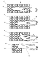
- FIGS. 4 to 7 show schematically different shapes and sizes of modules 12 .
- a person 48 which deactivates the individual segments 14 through corresponding movements is associated with each of the modules 12 , as described above.
- the size, height, and arrangement of the modules 12 can be adapted to the desired training program and/or therapeutic program.
- the device 10 can be adapted to the different training methods and/or training programs and different therapeutic methods and/or therapeutic programs.
- the device 10 can be used for competitive sport as well as for popular sport and general physical exercise and for therapeutic purposes in medicine.
- Modules 12 can be flexibly assembled from segments 14 .
- the corresponding specific requirements of the persons 48 can be met by the particular arrangement of the individual segments 14 or modules 12 , for example based on ergonomics. This makes possible configurations for training in different forms of sports.
- the device 10 can be adapted to a specific body height, a reaction radius and to tactile characteristics of the persons 48 to be activated.
- the device can also be easily adapted to the available space.
Landscapes
- Business, Economics & Management (AREA)
- Engineering & Computer Science (AREA)
- Entrepreneurship & Innovation (AREA)
- Physics & Mathematics (AREA)
- Educational Administration (AREA)
- Educational Technology (AREA)
- General Physics & Mathematics (AREA)
- Theoretical Computer Science (AREA)
- Radiation-Therapy Devices (AREA)
Abstract
The invention relates to the device for activating at least one person with at least one module (12) that can be perceptually controlled by the at least one person. According to the invention, the module (12) includes at least one means which can be used by the at least one person (48) to deactivate at least a part of the perceptual control of the at least one module (12) and/or deactivate the perceptual control of the at least one module (12) at least for a period of time.
Description
- This application is a non-provisional application based on serial No. 60/370,914, filed on Apr. 8, 2002.
- The invention relates to a device for activating at least one person.
- In the context of this invention, activating at least one person is to be understood as a specific movement training, an specific therapeutic exercise, a specific movement animation or the like of a person. The specific activation can be employed for sports, medical or therapeutic reasons.
- Training and/or therapeutic equipment and devices of different types are known in the art. Such equipment is generally known as sports and/or fitness equipment offer a person the possibility for a specific therapeutic exercise and/or a specific training. The known equipment can be static or dynamic. Different movements are possible depending on the equipment's design. It is also known to combine such devices with so-called minicomputers, so that different training patterns and/or movement patterns can be simulated. Ergometers should be mentioned at this point as a specific example.
- These known devices have the disadvantage that they have limited flexibility in their use, and may be suitable only for specific movements.
- It is therefore an object of the invention to provide a device of the aforedescribed type which has a simpler construction and can be flexibly adapted to different movements.
- According to the invention, the object is solved by a device having the characterizing features recited in claim 1. By providing the module with at least one means which can be used by the at least one person to deactivate at least a part of the perceptual control of the at least one module and/or deactivate the perceptual control of the at least one module at least for a period of time, a reaction of the at least one person for deactivating the perceptual control is advantageously elicited from the person through the perceptual control of the at least one module. The deactivation is connected with a quasi-forced or compulsory movement of the person, depending on the position of the perceptually controllable module relative to the at least one person. Accordingly, specific movements and responses of persons can be initiated, resulting in a very efficient therapeutic exercise and/or motion training.
- According to another embodiment of the invention, the module includes at least one controllable segment. In particular, the module advantageously includes a plurality of segments arranged in a predetermined grid pattern, in particular at intersecting vertical and/or horizontal and/or diagonal lines. Such configuration offers superior flexibility to visualize different movement patterns. In particular, individually configured therapeutic exercises or motion training for a specific person or a specific sport can be easily implemented, taking into account ergonomic considerations.
- According to a preferred embodiment of the invention, the at least one module can form a surface element, which is preferably configured curved or straight. In particular, the surface element can be concave or convex. This allows an optimal position of the individual segments of the modules relative to the at least one person, so that the therapeutic and/or training measures can not only be optimally adapted of the available space, but can in addition also be adapted to particular situations.
- According to another preferred embodiment, the at least one module can be arranged in front of and/or behind and/or to the left and/or to the right and/or above and/or underneath the at least one person. A plurality of modules, each of which can have a plurality of individual segments, can be combined into a device which allows specific therapeutic exercises and/or a specific motion training in several directions in space.
- According to the actual application of the device, for example as a training device in competitive sport, a training device in fitness centers, sports academies or therapy centers, such as rehabilitation centers and the like, a device suitable for the specific requirements can be assembled in modular form. More particularly, the device can be expanded, starting with a module that is located essentially opposite to the person to be activated, by at least one additional module that is oriented at an angle to the first module.
- Feasible is here a diagonal arrangement, in particular in a rectangular configuration as well as an arrangement with acute or obtuse angles. In the ticket, a concave and/or convex configured module allows a compact form several possibilities for applications in the aforedescribed areas.
- According to yet another advantageous embodiment of the invention, the segments emit optical and/or acoustic signals in response to the perceptual control. When the at least one person perceives the optical and/or acoustic signals, the person can deactivate exactly those segments that emit the optical and/or acoustic signals. The movement of the person is stimulated according to a presettable frequency and/or time duration of the emission of the optical and/or acoustic signals. It will be understood that different therapeutic exercises and/or motion training patterns can be defined by presetting the frequency and/or time duration of the optical and/or acoustic signals. The frequency and/or the time duration of the optical and/or acoustic signals of individual segments can also be varied during the duration of a training unit and/or therapeutic unit.
- According to still another advantageous embodiment, the segments can change their shape in response to the perceptual control, in particular through pneumatic and/or hydraulic control. This enables additional embodiments which allow the at least one person to either optically perceive or sense of the activation of a segment. The various combinations of optical and/or acoustic and/or pneumatic or hydraulic control also enable other therapeutic and training possibilities, for example, for vision- and/or hearing-impaired persons.
- According to another advantageous embodiment to the invention, the segments can include at least one illuminating means and, according to another preferred embodiment, a plurality of illuminating means that radiate electromagnetic waves in different wavelength ranges. Optical signals can be provided in different colors depending on the selection of the at least one illuminating means. Signaling in different colors can elicit different perceptual reaction from the persons to be activated, so that different reaction speeds of the persons can be obtained and/or trained and/or therapeutically implemented based on otherwise identical movement patterns by controlling the same segments with different color schemes.
- The at least one illuminating means is preferably implemented as a light emitting diode or the like, so that the illumination means can be easily integrated in the segments without requiring a large installation space, while also reducing the energy consumption of the illumination means.
- According to yet another advantageous embodiment of the invention, the segments can include interchangeable cover elements which more particularly can have a different shape and/or a different material strength and/or can be made of a different material. This advantageously also allows adaptation to the different training and/or therapeutic measures. For example, the material strengths and/or material selection and/or form can produce different activation forces of the segments necessary to deactivate the individual segments. In this way, the force exerted during the movement can be trained or included in the therapy in addition to the reaction speed. Also, different training methods can be easily incorporated for different types of sports or the like. Preferably, the cover elements can be made of plastic, in particular of an optically transparent plastic. In this way, the shape and/or material strength of the cover lids can be configured in addition to optical signaling. In particular, the weight of the cover elements and hence also of the segments and the modules is minimized, so that the device can be configured for mobility and flexibility.
- According to still another advantageous embodiment of the invention, the switching means for deactivating the individual segments can be operated contactless or mechanically. Depending on the selected embodiment, a segment can be deactivated, for example, by applying an actuation force—which, as described above, can be set to be variable—or contact-less, for example with an infrared sensor or the like, when a part of a person's body approaches the segment to be deactivated.
- According to yet another advantageous embodiment of the invention, the device includes a controller for controlling the at least one module and/or for acquiring and/or recording the deactivation of the at least one segment and/or the at least one module. In particular, in another preferred embodiment of the invention, the controller can be freely programmed, so that different training programs and/or therapeutic programs can be implemented with the device of the invention. For example, the frequency and/or the time duration of the signals emitted by the individual segments can be programmed. In particular, different degrees of difficulty, different movement patterns to be trained and different training times can be programmed. For example, the controller can be programmed by taking into consideration the ergonomics of the person.
- Advantageously, the controller can include means for person-specific programming. In this way, the device can be programmed for individuals depending on the desired degree of difficulty and/or the desired movement patterns. The device of the invention can then be flexibly used for many purposes.
- Advantageously, the controller can include storage means for person-specific storage of the activation and/or deactivation processes, wherein the controller preferably includes at least one input/output unit for reading and/or writing person-specific activation and/or deactivation processes. In this way, the programming code for the individual person can advantageously be intermediately stored, so that the controller and hence also the device need not be reprogrammed each time from the beginning. The deactivation processes can at the same time be acquired and stored to make them available for later comprehensive evaluation. In particular, reaction times between the activation of the segments and deactivation of the segments can be measured so as to arrive at conclusions about the motion performance of the person to be activated. The training programs and/or therapeutic programs can then be easily optimized. In particular, deactivation times of the individual segments can be compared with each other, so that the motion performance of the person to be activated can be matched exactly and optionally calculatingly trained.
- In addition, according to an advantageous embodiment of the invention, the input/output unit can be a chip card reader. In this way, the person-specific programming and/or the person-specific control and/or deactivation processes can be stored on the chip card, so that the device can be easy be programmed by inserting the chip card into and/or pulling the chip card out of the controller. The acquired deactivation processes can also be transferred in this way. Accordingly, the individual results can subsequently be easily acquired, archived and/or processed—independent of the actual device of the invention.
- Finally, according to a preferred embodiment of the invention, the controller can be connected to the at least one module via an interface which can be wireless or wired. This interface is preferably bidirectional, so that the control signals and/or the deactivation signals can be easy exchanged between the at least one module and the controller. The interface can be, for example, an infrared interface, so that no additional wires have to be connected. However, other embodiments using, for example, wireless transmission, optical waveguides, electrical wiring and the like are also feasible.
- Additional preferred embodiments of the invention are recited in the dependent claims.
- The embodiments of the invention will be described hereinafter with reference to the appended drawings. It is shown in:
- FIG. 1 a schematic view of the device of the invention;
- FIG. 2 a block diagram depicting the function of the device of the invention;
- FIGS. 3 a to 3 c different views of a segment of the device of the invention; and
- FIGS. 4 to 7 schematically, different embodiments of the invention.
- FIG. 1 shows a device, indicated with
reference numeral 10, for activating at least one person (not shown in FIG. 1). The device can include at least onemodule 12 comprised of a plurality ofsegments 14. As can be seen from the illustration in FIG. 1, the segments are arranged in a grid pattern comprised ofrows 16 andcolumns 18. The number ofrows 16 andcolumns 18 is variable. The number ofsegments 14 can be freely selected depending on the desired configuration or desired training and/or therapy patterns, as described below. - As seen in FIG. 1, the
module 12 can be formed as a unit with a flat surface. According to other embodiments (not shown), themodule 12 can also have a curved concave and/or convex shape—in the direction of thecolumns 16 and/or in the direction of therows 18. The shape of thesegments 14 can be selectively combined into the aforedescribed concave or convex shapes. Thesegments 14 can also be flexible, so that their shape can be a changeably adapted to the desired applications. - A
controller 20 which communicates with themodule 12 via abidirectional interface 22 is associated with themodule 12. Each of thesegments 14 includes at least one illumination means 24, in particular at least one light emitting diode that can be controlled by thecontroller 20, i.e., supplied with a supply voltage. In addition, eachsegment 14 includes a schematically indicated switching means 26 for deactivating the illumination means 24 that is driven by thecontroller 20. - In the diagram of FIG. 1, only one illumination means 24 and one switching means 26 associated with one
segment 14 is shown. However, it will be understood that each of thesegments 14 can have such illumination means 24 and switching means 26. - The individual illumination means 24 of the
segments 14 can be variably controlled by thecontroller 20. Each illumination means 24 can be individually controlled by associating eachsegment 14 with row and/or a column information. Thecontroller 20 can also define a control frequency and/or a time duration for each of the illumination means 24. - The
controller 20 includes control devices 28 (indicated only schematically) which can be used to program thecontroller 20. Integrated in thecontroller 20 are means 30 which include, in particular, storage means, computing means and the like and which can be used to process signals. In addition, the controller includes an input andoutput unit 32 which is advantageously implemented as achip card reader 34. Achip card 36 with at least one memory means 38 can be inserted into thechip card reader 34. - The
device 10 depicted in FIG. 1 has the following functionality illustrated in the flow diagram of FIG. 2: - A person using the
device 10 has in his/her possession the person-specific chip card 36 which is inserted into thecontroller 20 in afirst step 50. In anext step 52, thecontroller 20 receives from the memory means 38 of thechip card 36 the person-specific programming information and stores the programming information in themeans 30. In the followingstep 54, themeans 30 determine from the person-specific programming information the control signals for the illuminating means 24 of theindividual segments 14. This relates in particular to the order, the selection, the frequency and/or the duration with which thedifferent segments 14 are driven. Depending of the person-specific programming, not allsegments 14 need to be energized, but rather only a subset of thesegments 14 associated with the desired training and/or therapeutic program. The person-specific programming information can also contain the total duration of the training program and/or therapeutic program. The control program is started by activating “Start” (step 56) of thedevice 10, for example, by activating one of thepushbuttons 28 or the like. The person then takes up position within reach of themodule 12 and deactivates with his/her limbs, for example his/her hand and/or feet, the previously activatedsegment 14. Based on the optical signal transmitted by the illuminating means 24, the person recognizes whichsegment 14 is activated and therefore has to be deactivated. According to additional embodiments, the optical signal can be combined with an acoustic signal. Deactivation of thesegment 14 by the person is transmitted to thecontroller 20 via the interface 22 (step 58), with the controller intermediately storing the information in themeans 30. In particular, the delay between the activation of asegment 14 and its deactivation can be measured. According to this method, the person-specific program is processed during the selected time period. - After the training and/or therapeutic program is concluded, the intermediately stored deactivation information of the person can be read onto the
memory chip 38 of the person-specific chip card 36 (step 60), so that this information is available for a subsequent detailed evaluation or archiving or the like. - The use of a
chip card 36 is only exemplary, and other suitable memory means and/or acquisition means can, of course, also be used. - According to another embodiment of the invention (not shown), the person to be activated can be provided with or connected to at least one measurement means, which measures at least one body signal, such as the pulse rate, blood pressure, temperature, brain waves and the like. The at least one measurement means can be connected with the
controller 20 so as to affect the control of thedevice 10 depending on the immediate condition of the person. - FIG. 3 shows different views of a
segment 14. FIG. 3a shows a top view of thesegment 14, whereas FIG. 3b shows a cross-sectional view. As seen in the cross-sectional view of FIG. 3b, thesegment 14 consists of abase element 40 and acover element 42. Thebase element 40 can be attached to a support, for example a movable wall or a fixed wall of a room. Thecover element 42 can be connected to thebase element 40 throughsnap connections 44 or the like. Thecover element 42 is made of an optically transparent plastic, so that the illuminating means 24 arranged in the interior (not shown in FIG. 3) of thesegment 14 can radiate the electromagnetic waves through thecover element 42. Thecover element 42 also forms an actuation surface 46, allowing the person to deactivate the illuminating means 24 by operating the switchingelement 26. With this arrangement, thecover element 42 can have a shape and/or or material strength or material properties adapted to the specific actuation force required for deactivating the illuminatingmeans 24. For example, a different actuation force for deactivating the corresponding illuminating means 24 can be set for different training programs or therapeutic programs. In this way, a specific training program for certain movements and/or certain muscles of the person can be implemented. - FIG. 3 c finally shows at a reduced scale a
segment 14 wherein thecover element 42 interlocks with abase element 40. Not shown for sake of clarity are the illuminating means 24 as well as the switching means 26 and the signal and/or voltage lines to thesegments 14. - FIGS. 4 to 7 show schematically different shapes and sizes of
modules 12. Aperson 48 which deactivates theindividual segments 14 through corresponding movements is associated with each of themodules 12, as described above. The size, height, and arrangement of themodules 12 can be adapted to the desired training program and/or therapeutic program. - It is clear from the features described above that by using the
device 10,persons 48 can optimally train their condition, reaction time, speed and fitness with the help of optical signals using touch and action. In particular, specific movement patterns and reactions can be trained. Through simple modifications, thedevice 10 can be adapted to the different training methods and/or training programs and different therapeutic methods and/or therapeutic programs. Thedevice 10 can be used for competitive sport as well as for popular sport and general physical exercise and for therapeutic purposes in medicine.Modules 12 can be flexibly assembled fromsegments 14. The corresponding specific requirements of thepersons 48 can be met by the particular arrangement of theindividual segments 14 ormodules 12, for example based on ergonomics. This makes possible configurations for training in different forms of sports. In particular, thedevice 10 can be adapted to a specific body height, a reaction radius and to tactile characteristics of thepersons 48 to be activated. The device can also be easily adapted to the available space. - Acquiring the deactivation processes makes it possible to determine the sensory and switching reactions of the
persons 48 and hence to evaluate their reaction, therapeutic parameters and progress with treatment and training. - List of Reference Numerals
- 10 device
- 12 module
- 14 segment
- 16 row
- 18 column
- 20 controller
- 22 interface
- 24 illumination means
- 26 switching means
- 28 actuation devices
- 30 means
- 32 input/output unit
- 34 chip card reader
- 36 chip card
- 38 memory means
- 40 base element
- 42 cover element
- 44 snap connection
- 46 actuation surface
- 48 person
- 50 step
- 52 step
- 54 step
- 56 step
- 57 step
- 60 step
Claims (36)
1. Device for activating at least one person (48) with at least one module (12) that can be perceptually controlled by the at least one person (48), wherein the module (12) includes at least one means which can be used by the at least one person (48) to deactivate at least a part of the perceptual control of the at least one module (12) and/or deactivate the perceptual control of the at least one module (12) at least for a period of time.
2. Device according to claim 1 , wherein the module (12) includes at least one controllable segment (14).
3. Device according to claim 1 , wherein the module (12) includes a plurality of segments (14) arranged in a predetermined grid pattern.
4. Device according to claim 1 , wherein the segments (14) are arranged at intersecting vertical and/or horizontal and/or diagonal lines.
5. Device according to claim 1 , wherein the at least one module (12) forms a surface element.
6. Device according to claim 1 , wherein the surface element is straight.
7. Device according to claim 1 , wherein the surface element is curved.
8. Device according to claim 1 , wherein the surface element is concave.
9. Device according to claim 1 , wherein the surface element is convex.
10. Device according to claim 1 , wherein the device (10) includes at least two modules (12).
11. Device according to claim 1 , wherein the at least two modules (12) can be arranged at a selectable angle relative to each other.
12. Device according to claim 1 , wherein the at least two modules (12) can be arranged at right angles with respect to each other.
13. Device according to claim 1 , wherein the at least two modules (12) are arranged opposite of each other.
14. Device according to claim 1 , wherein the at least one module (12) is arranged in front of an/or behind and/or to the left and/or to the right and/or above and/or underneath the at least one person (48).
15. Device according to claim 1 , wherein in response to the perceptual control, the segments (14) emit optical and/or acoustic signals.
16. Device according to claim 1 , wherein in response to the perceptual control, the segments change their shape.
17. Device according to claim 16 , wherein the control is pneumatically and/or hydraulically.
18. Device according to claim 1 , wherein the segments include at least one illuminating means (24).
19. Device according to claim 1 , wherein the segments (14) includes a plurality of illuminating means (24) that radiate electromagnetic waves in different wavelength ranges.
20. Device according to claim 1 , wherein the illuminating means (24) are light-emitting diodes or the like.
21. Device according to claim 1 , wherein the segments (14) comprise interchangeable cover elements (42).
22. Device according to claim 1 , wherein the cover elements (42) have a different shape and/or a different material strength and/or are made of a different material.
23. Device according to claim 1 , wherein the cover elements (42) are made of plastic, in particular an optically transparent plastic.
24. Device according to claim 1 , wherein the at least one means for deactivating the at least one segment (14) is a switching means (23).
25. Device according to claim 1 , wherein the switching means (26) is a switch contact.
26. Device according to claim 1 , wherein the switch contact can be operated contactless or mechanically.
27. Device according to claim 1 , wherein the device (10) comprises a controller (20) for controlling the at least one module (12) and/or for acquiring and/or recording the deactivation of the at least one segment (14) and/or the at least one module (12).
20. Device according to claim 1 , wherein the controller (20) can be freely programmed.
29. Device according to claim 1 , wherein the controller (20) includes means for person-specific programming.
30. Device according to claim 1 , wherein the controller (20) includes storage means for person-specific storage of the activation and/or deactivation processes.
31. Device according to claim 1 , wherein the controller (20) includes at least one input/output unit for reading and/or writing person-specific actuation and/or deactivation processes.
32. Device according to claim 1 , wherein the input/output unit (32) is a chip card reader (34)
33. Device according to claim 1 , wherein the controller (20) is connected to the at least one module (12) via an interface (22).
34. Device according to claim 1 , wherein the interface (22) is implemented wireless or wired.
35. Device according to claim 1 , wherein the interface (22) is an infrared interface.
36. Device according to claim 1 , wherein the interface (22) operates bidirectionally.
Priority Applications (1)
| Application Number | Priority Date | Filing Date | Title |
|---|---|---|---|
| US10/406,900 US20030190955A1 (en) | 2002-04-08 | 2003-04-03 | Device for activating at least one person |
Applications Claiming Priority (2)
| Application Number | Priority Date | Filing Date | Title |
|---|---|---|---|
| US37091402P | 2002-04-08 | 2002-04-08 | |
| US10/406,900 US20030190955A1 (en) | 2002-04-08 | 2003-04-03 | Device for activating at least one person |
Publications (1)
| Publication Number | Publication Date |
|---|---|
| US20030190955A1 true US20030190955A1 (en) | 2003-10-09 |
Family
ID=28678368
Family Applications (1)
| Application Number | Title | Priority Date | Filing Date |
|---|---|---|---|
| US10/406,900 Abandoned US20030190955A1 (en) | 2002-04-08 | 2003-04-03 | Device for activating at least one person |
Country Status (1)
| Country | Link |
|---|---|
| US (1) | US20030190955A1 (en) |
Cited By (1)
| Publication number | Priority date | Publication date | Assignee | Title |
|---|---|---|---|---|
| US20070045403A1 (en) * | 2005-08-31 | 2007-03-01 | Slonecker David B Jr | System and method for locking and unlocking a financial account card |
Citations (23)
| Publication number | Priority date | Publication date | Assignee | Title |
|---|---|---|---|---|
| US3848723A (en) * | 1973-07-23 | 1974-11-19 | L Hogue | Adapter key caps |
| US4121488A (en) * | 1976-03-08 | 1978-10-24 | Nep Company, Ltd. | Step-on type tone scale play device |
| US4565460A (en) * | 1984-03-05 | 1986-01-21 | Kline Alva C | Convex key top configurations |
| US4720789A (en) * | 1985-10-31 | 1988-01-19 | Bally Manufacturing Corporation | Video exercise or game floor controller with position indicating foot pads |
| US4755072A (en) * | 1986-10-15 | 1988-07-05 | Hoornweg Andries P | Removable, transparent, colored key caps for color coding a keyboard |
| US5139261A (en) * | 1989-09-15 | 1992-08-18 | Openiano Renato M | Foot-actuated computer game controller serving as a joystick |
| US5183346A (en) * | 1992-05-15 | 1993-02-02 | Herbert Tesar | Keycap overlay snap-on system |
| US5290995A (en) * | 1991-12-20 | 1994-03-01 | Esab Welding Products, Inc. | Plasma arc cutting system having fluid metering and power control systems |
| US5584779A (en) * | 1995-04-10 | 1996-12-17 | Wendy S. Knecht | Step exercising system and method |
| US5667459A (en) * | 1994-11-10 | 1997-09-16 | Su; Li-Ping | Computerized exercise game machine |
| US5837952A (en) * | 1996-06-04 | 1998-11-17 | Combi Corporation | Mat switch |
| US6110073A (en) * | 1999-02-03 | 2000-08-29 | Tread Pad Partners, Llc | Physical fitness device |
| US6227968B1 (en) * | 1998-07-24 | 2001-05-08 | Konami Co., Ltd. | Dance game apparatus and step-on base for dance game |
| US6450886B1 (en) * | 1999-04-09 | 2002-09-17 | Konami Co., Ltd. | Foot switcher, foot switch sheet and mat for use in the same |
| US6450888B1 (en) * | 1999-02-16 | 2002-09-17 | Konami Co., Ltd. | Game system and program |
| US20030078138A1 (en) * | 2001-10-19 | 2003-04-24 | Konami Corporation | Exercise assistance controlling method and exercise assisting apparatus |
| US6572108B1 (en) * | 2002-01-30 | 2003-06-03 | Radica China Ltd | Game pad controller |
| US6658773B2 (en) * | 2002-03-11 | 2003-12-09 | Dennis Rohne | Label with luminescence inside |
| US6685480B2 (en) * | 2000-03-24 | 2004-02-03 | Yamaha Corporation | Physical motion state evaluation apparatus |
| US6695694B2 (en) * | 2000-02-23 | 2004-02-24 | Konami Corporation | Game machine, game device control method, information storage medium, game distribution device, and game distribution method |
| US6743971B1 (en) * | 2003-01-13 | 2004-06-01 | Red Tower, Inc. | Electronic musical keyboard operated by foot for amusement and exercise |
| US6758753B1 (en) * | 1999-06-18 | 2004-07-06 | Konami Co., Ltd. | Input apparatus for game systems |
| US6905413B1 (en) * | 1999-08-10 | 2005-06-14 | Konami Corporation | Music game system |
-
2003
- 2003-04-03 US US10/406,900 patent/US20030190955A1/en not_active Abandoned
Patent Citations (23)
| Publication number | Priority date | Publication date | Assignee | Title |
|---|---|---|---|---|
| US3848723A (en) * | 1973-07-23 | 1974-11-19 | L Hogue | Adapter key caps |
| US4121488A (en) * | 1976-03-08 | 1978-10-24 | Nep Company, Ltd. | Step-on type tone scale play device |
| US4565460A (en) * | 1984-03-05 | 1986-01-21 | Kline Alva C | Convex key top configurations |
| US4720789A (en) * | 1985-10-31 | 1988-01-19 | Bally Manufacturing Corporation | Video exercise or game floor controller with position indicating foot pads |
| US4755072A (en) * | 1986-10-15 | 1988-07-05 | Hoornweg Andries P | Removable, transparent, colored key caps for color coding a keyboard |
| US5139261A (en) * | 1989-09-15 | 1992-08-18 | Openiano Renato M | Foot-actuated computer game controller serving as a joystick |
| US5290995A (en) * | 1991-12-20 | 1994-03-01 | Esab Welding Products, Inc. | Plasma arc cutting system having fluid metering and power control systems |
| US5183346A (en) * | 1992-05-15 | 1993-02-02 | Herbert Tesar | Keycap overlay snap-on system |
| US5667459A (en) * | 1994-11-10 | 1997-09-16 | Su; Li-Ping | Computerized exercise game machine |
| US5584779A (en) * | 1995-04-10 | 1996-12-17 | Wendy S. Knecht | Step exercising system and method |
| US5837952A (en) * | 1996-06-04 | 1998-11-17 | Combi Corporation | Mat switch |
| US6227968B1 (en) * | 1998-07-24 | 2001-05-08 | Konami Co., Ltd. | Dance game apparatus and step-on base for dance game |
| US6110073A (en) * | 1999-02-03 | 2000-08-29 | Tread Pad Partners, Llc | Physical fitness device |
| US6450888B1 (en) * | 1999-02-16 | 2002-09-17 | Konami Co., Ltd. | Game system and program |
| US6450886B1 (en) * | 1999-04-09 | 2002-09-17 | Konami Co., Ltd. | Foot switcher, foot switch sheet and mat for use in the same |
| US6758753B1 (en) * | 1999-06-18 | 2004-07-06 | Konami Co., Ltd. | Input apparatus for game systems |
| US6905413B1 (en) * | 1999-08-10 | 2005-06-14 | Konami Corporation | Music game system |
| US6695694B2 (en) * | 2000-02-23 | 2004-02-24 | Konami Corporation | Game machine, game device control method, information storage medium, game distribution device, and game distribution method |
| US6685480B2 (en) * | 2000-03-24 | 2004-02-03 | Yamaha Corporation | Physical motion state evaluation apparatus |
| US20030078138A1 (en) * | 2001-10-19 | 2003-04-24 | Konami Corporation | Exercise assistance controlling method and exercise assisting apparatus |
| US6572108B1 (en) * | 2002-01-30 | 2003-06-03 | Radica China Ltd | Game pad controller |
| US6658773B2 (en) * | 2002-03-11 | 2003-12-09 | Dennis Rohne | Label with luminescence inside |
| US6743971B1 (en) * | 2003-01-13 | 2004-06-01 | Red Tower, Inc. | Electronic musical keyboard operated by foot for amusement and exercise |
Cited By (2)
| Publication number | Priority date | Publication date | Assignee | Title |
|---|---|---|---|---|
| US20070045403A1 (en) * | 2005-08-31 | 2007-03-01 | Slonecker David B Jr | System and method for locking and unlocking a financial account card |
| US7383988B2 (en) * | 2005-08-31 | 2008-06-10 | Metavante Corporation | System and method for locking and unlocking a financial account card |
Similar Documents
| Publication | Publication Date | Title |
|---|---|---|
| US12447353B2 (en) | Light therapy device and method for delivery of light therapy to a body part | |
| KR20050006148A (en) | Device for stimulating at least one person | |
| US4702475A (en) | Sports technique and reaction training system | |
| US5719561A (en) | Tactile communication device and method | |
| US5593381A (en) | Skin and tissue treatment and stimulation device and method | |
| KR101649522B1 (en) | Multifunction Beauty Equipment | |
| US20060190057A1 (en) | Synthetic traveling wave transcutaneous electrical stimulation device | |
| HUE034433T2 (en) | Modular robotic tiles for physical interaction | |
| CN101316624A (en) | Light therapy device | |
| EP3154631B1 (en) | Phototherapy device with pain location input. | |
| EP3811911B1 (en) | Training device | |
| CN214318510U (en) | Massage device | |
| CN112367957A (en) | Method and apparatus for providing relaxant therapy massage | |
| US20060282026A1 (en) | Method and apparatus for controlling massage using pressure inducing elements | |
| GB2527136A (en) | Prosthetic hand for human interaction through haptic feedback | |
| US20030190955A1 (en) | Device for activating at least one person | |
| WO2006081883A2 (en) | Skin surface stimulation using a matrix of controlled stimulus signals | |
| KR20200110021A (en) | Apparatus for providing massage using marker and operating method thereof | |
| US5755749A (en) | Change control method using three-dimensional 1/F fluctuation, recording medium storing the method, and change control device using three-dimensional 1/F fluctuation | |
| US6623273B2 (en) | Portable speech therapy device | |
| US11327557B2 (en) | Skin interface system | |
| CA1260579A (en) | Sports technique and reaction training system | |
| EP1941857A2 (en) | Apparatus and method for stimulation of the human body | |
| CN109803627B (en) | Bracket for spring mat system and device for sensory training of a person | |
| JP2008161666A (en) | Rehabilitation intelligence enhancement game system |
Legal Events
| Date | Code | Title | Description |
|---|---|---|---|
| AS | Assignment |
Owner name: RYLL, THOMAS, GERMANY Free format text: ASSIGNMENT OF ASSIGNORS INTEREST;ASSIGNOR:WEISS, FRANK;REEL/FRAME:013725/0498 Effective date: 20030404 |
|
| STCB | Information on status: application discontinuation |
Free format text: ABANDONED -- FAILURE TO RESPOND TO AN OFFICE ACTION |