US20030190890A1 - Local multi-point distribution system architectures - Google Patents
Local multi-point distribution system architectures Download PDFInfo
- Publication number
- US20030190890A1 US20030190890A1 US10/427,431 US42743103A US2003190890A1 US 20030190890 A1 US20030190890 A1 US 20030190890A1 US 42743103 A US42743103 A US 42743103A US 2003190890 A1 US2003190890 A1 US 2003190890A1
- Authority
- US
- United States
- Prior art keywords
- signal
- customer
- operative
- central office
- hub
- Prior art date
- Legal status (The legal status is an assumption and is not a legal conclusion. Google has not performed a legal analysis and makes no representation as to the accuracy of the status listed.)
- Granted
Links
- 238000004891 communication Methods 0.000 claims abstract description 30
- 239000000835 fiber Substances 0.000 claims description 13
- 238000005516 engineering process Methods 0.000 description 10
- 239000008186 active pharmaceutical agent Substances 0.000 description 1
- 230000005540 biological transmission Effects 0.000 description 1
- 230000010354 integration Effects 0.000 description 1
- 230000001502 supplementing effect Effects 0.000 description 1
- 230000003245 working effect Effects 0.000 description 1
Images

Classifications
-
- H—ELECTRICITY
- H04—ELECTRIC COMMUNICATION TECHNIQUE
- H04W—WIRELESS COMMUNICATION NETWORKS
- H04W84/00—Network topologies
- H04W84/02—Hierarchically pre-organised networks, e.g. paging networks, cellular networks, WLAN [Wireless Local Area Network] or WLL [Wireless Local Loop]
- H04W84/10—Small scale networks; Flat hierarchical networks
- H04W84/14—WLL [Wireless Local Loop]; RLL [Radio Local Loop]
Definitions
- the present invention relates to architectures for local multipoint distribution system (LMDS) applications.
- LMDS local multipoint distribution system
- LMDS Local multipoint distribution system
- LMDS in an existing architecture involves broadcasting microwave signals at frequencies at or above 28 Ghz to small receiver dishes, typically installed on the top of apartment buildings. At that high frequency, line-of-sight is required for maximum signal performance. The received LMDS signal may then be distributed through the building. LMDS technologies may also be used at lower frequencies to limit the strict line-of-sight limitations.
- existing LMDS systems use the LMDS receiver to serve one customer or subscriber, with each different customer or subscriber having a dedicated LMDS receiver.
- a broadband communication system comprising a central office connected to a high speed network, a local multipoint distribution system (LMDS) hub, a local multipoint distribution system (LMDS) remote terminal, and a plurality of customer digital signal lines connected to the remote terminal.
- the LMDS hub connects to an antenna that operates to transmit a signal.
- a fiber connects the central office to the hub to send the signal from the central office to the hub, allowing the antenna to transmit the signal.
- the remote terminal operates to receive the signal and further operates to separate the signal into a plurality of customer signals corresponding to a plurality of customers. Each customer digital signal line operates to send a customer signal to the corresponding customer.
- a broadband communication system comprises a central office, a local multipoint distribution system (LMDS), remote terminal, and a plurality of customer digital signal lines.
- the central office is connected to a high speed network and includes a local multipoint distribution system (LMDS) hub.
- the LMDS hub is connected to an antenna operative to transmit a signal.
- the remote terminal operates to receive the signal and further operates to separate the signal into a plurality of customer signals corresponding to a plurality of customers.
- the customer digital signal lines are connected to the remote terminal, and are operative to send a customer signal to the corresponding customer.
- a broadband communication system comprises a central office connected to a high speed network, a local multipoint distribution system (LMDS) hub, and a local multipoint distribution system (LMDS) remote terminal.
- the LMDS hub includes an antenna operative to transmit a signal.
- a fiber connects the central office to the hub to send the signal from the central office to allow the antenna to transmit the signal.
- the remote terminal operates to receive the signal.
- a fiber connects the remote terminal to a network interface node operative to receive the signal and further operative to separate the signal into a plurality of customer signal corresponding to a plurality of customers.
- the signals are delivered with a plurality of customer digital signal lines connected to the node. Each customer digital signal line operates to send a customer signal to the corresponding customer.
- a broadband communication system in which a central office is connected to a high speed network is provided.
- the central office is connected to a network interface node with a plurality of customer subscriber lines connected thereto.
- the system comprises a local multipoint distribution system (LMDS) hub connected to an antenna operative to transmit a signal.
- the hub is connected to the central office.
- the system further comprises a local multipoint distribution system (LMDS) remote terminal.
- the remote terminal operates to receive the signal and further operates to send the signal to the network interface node, thereby increasing total bandwidth inflow to the network interface node to allow additional customer subscriber lines to be connected thereto.
- LMDS local multipoint distribution system
- systems of the present invention provide architectures for LMDS applications for high and low speed data services, in addition to allowing integration of LMDS technology into existing wireline networks.
- LMDS technology in accordance with the present invention may be utilized to extend the reach of land line networks, advantageously reducing the cost of current land line networks.
- LMDS technologies are generally utilized in the gigahertz frequency range, lower frequencies may be used as appropriate for a particular application, depending on the needed distance between the broadcasting and receiving antennas, and other conditions as appreciated by one of ordinary skill in the art.
- the high bandwidth of LMDS technologies makes embodiments of the present invention useful for data, voice, and combinational transmissions including both voice and data.
- FIG. 1 is a broadband communication system utilizing a first LMDS architecture of the present invention
- FIG. 2 is a broadband communication system utilizing a second LMDS architecture of the present invention.
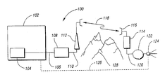
- FIG. 3 is a broadband communication system utilizing a third LMDS architecture of the present invention, and further illustrates LMDS architecture supplementing an existing wireline network (shown in dashed line).
- a broadband communication system of the present invention is generally indicated at 10 .
- System 10 includes a central office 12 connected to a high speed network 14 .
- a suitable high speed network is an asynchronic transfer mode (ATM) network.
- Network 14 is connected by a fiber 16 to a local multipoint distribution system (LMDS) hub 18 .
- Fiber 16 is used to send a signal from central office 12 to LMDS hub 18 .
- the signal may be routed along line 20 to antenna 22 , which in turn transmits the signal.
- line 20 is coaxial cable.
- Tower antenna 22 transmits the signal which is received by a local multipoint distribution system (LMDS) remote terminal 24 .
- LMDS local multipoint distribution system
- LMDS remote terminal 24 and tower antenna 22 communicate in preferably two-way communication as indicated by double arrow 26 .
- Remote terminal 24 operates to separate the received signal into a plurality of customer signals corresponding to a plurality of customers. Each customer is served by a separate digital signal line 28 , 30 , 32 .
- Customer signal lines 28 , 30 , 32 connect to customer sites 34 , 36 , 38 , respectively.
- digital signal lines 28 , 30 , 32 may take a variety of forms.
- the digital signal lines of this LMDS architecture and other LMDS architectures of the present invention are xDSL (of which VDSL is a suitable category thereof), and DS lines such as DS0 and DS1 lines.
- System 50 includes a central office 52 connected to a high speed network 54 , and including an LMDS hub 56 .
- LMDS hub 56 is connected to an antenna 58 .
- Antenna 58 is operative to transmit a signal.
- Antenna 58 transmits the signal for reception by receiving antenna 60 at LMDS remote terminal 62 .
- system 50 is configured for two-way communication as indicated by double arrow 64 .
- Remote terminal 62 is shown in greater detail than remote terminal 24 (FIG. 1); but, of course, it is to be appreciated that various arrangements for the internal workings of the remote terminals are apparent to and appreciated by those skilled in the LMDS communications art.
- Remote terminal 62 includes an LMDS modem 66 to convert the radio frequency signal to a digital signal, and is connected to a multiplexer 68 .
- multiplexer 68 may take a variety of forms, such as for example, a digital subscriber line access multiplexer (DSLAM) or a traditional demultiplexer for use with DS0 standard two wire twisted pairs.
- DSLAM digital subscriber line access multiplexer
- a plurality of customer digital signal lines, with separate lines indicated at 70 , 72 , 74 connect to customer sites 76 , 78 , 80 , respectively.
- System 100 includes a central office 102 connected to a high speed network 104 , with a fiber 106 connected in between central office 102 and an LMDS hub 108 .
- LMDS hub 108 connects along line 110 to tower antenna 112 .
- Tower antenna 112 transmits the signal to LMDS remote terminal 114 which has receiving antenna 116 .
- two-way communication is allowed as indicated by double arrow 118 .
- Remote terminal 114 connects through a fiber 120 into network 122 , and eventually to an interface node 124 .
- an LMDS architecture of the present invention may be utilized to expand the capabilities of an existing wire line network, indicated in hidden line at 126 . That is, additional bandwidth demand may arise at network interface node 124 , requiring the system provider to find a way to increase total bandwidth inflow to node 124 .
- an LMDS architecture may be utilized as an alternative to the expensive laying of fiber by instead providing an LMDS link from a new LMDS hub. Still further, in accordance with the present invention, LMDS architectures may be utilized to overcome obstacles that would make the laying of fiber difficult or very costly.
Landscapes
- Engineering & Computer Science (AREA)
- Computer Networks & Wireless Communication (AREA)
- Signal Processing (AREA)
- Mobile Radio Communication Systems (AREA)
Abstract
Description
- The present invention relates to architectures for local multipoint distribution system (LMDS) applications.
- Local multipoint distribution system (LMDS) in an existing architecture involves broadcasting microwave signals at frequencies at or above 28 Ghz to small receiver dishes, typically installed on the top of apartment buildings. At that high frequency, line-of-sight is required for maximum signal performance. The received LMDS signal may then be distributed through the building. LMDS technologies may also be used at lower frequencies to limit the strict line-of-sight limitations. In general, existing LMDS systems use the LMDS receiver to serve one customer or subscriber, with each different customer or subscriber having a dedicated LMDS receiver.
- Although existing deployment of LMDS technologies has been quite limited, the higher frequencies and additional bandwidth associated therewith is not yet being utilized to its full potential. For the foregoing reasons, there is a need for LMDS architectures that overcome limitations of the prior art and utilize LMDS technologies to the fullest.
- It is, therefore, an object of the present invention to provide a broadband communication system utilizing LMDS technologies to extend the reach of broadband service.
- It is another object of the present invention to integrate LMDS technology into existing wireline networks to expand network capabilities, extending the reach of land line networks, and reducing the cost of current land line networks.
- In carrying out the above objects, a broadband communication system is provided. The system comprises a central office connected to a high speed network, a local multipoint distribution system (LMDS) hub, a local multipoint distribution system (LMDS) remote terminal, and a plurality of customer digital signal lines connected to the remote terminal. The LMDS hub connects to an antenna that operates to transmit a signal. A fiber connects the central office to the hub to send the signal from the central office to the hub, allowing the antenna to transmit the signal. The remote terminal operates to receive the signal and further operates to separate the signal into a plurality of customer signals corresponding to a plurality of customers. Each customer digital signal line operates to send a customer signal to the corresponding customer.
- Further, in carrying out the present invention, a broadband communication system comprises a central office, a local multipoint distribution system (LMDS), remote terminal, and a plurality of customer digital signal lines. The central office is connected to a high speed network and includes a local multipoint distribution system (LMDS) hub. The LMDS hub is connected to an antenna operative to transmit a signal. The remote terminal operates to receive the signal and further operates to separate the signal into a plurality of customer signals corresponding to a plurality of customers. The customer digital signal lines are connected to the remote terminal, and are operative to send a customer signal to the corresponding customer.
- Still further, in carrying out the present invention, a broadband communication system comprises a central office connected to a high speed network, a local multipoint distribution system (LMDS) hub, and a local multipoint distribution system (LMDS) remote terminal. The LMDS hub includes an antenna operative to transmit a signal. A fiber connects the central office to the hub to send the signal from the central office to allow the antenna to transmit the signal. The remote terminal operates to receive the signal. A fiber connects the remote terminal to a network interface node operative to receive the signal and further operative to separate the signal into a plurality of customer signal corresponding to a plurality of customers. The signals are delivered with a plurality of customer digital signal lines connected to the node. Each customer digital signal line operates to send a customer signal to the corresponding customer.
- Yet further, in carrying out the present invention, a broadband communication system in which a central office is connected to a high speed network is provided. The central office is connected to a network interface node with a plurality of customer subscriber lines connected thereto. The system comprises a local multipoint distribution system (LMDS) hub connected to an antenna operative to transmit a signal. The hub is connected to the central office. The system further comprises a local multipoint distribution system (LMDS) remote terminal. The remote terminal operates to receive the signal and further operates to send the signal to the network interface node, thereby increasing total bandwidth inflow to the network interface node to allow additional customer subscriber lines to be connected thereto.
- The advantages associated with embodiments of the present invention are numerous. For example, systems of the present invention provide architectures for LMDS applications for high and low speed data services, in addition to allowing integration of LMDS technology into existing wireline networks. As such, LMDS technology in accordance with the present invention may be utilized to extend the reach of land line networks, advantageously reducing the cost of current land line networks. Further, although LMDS technologies are generally utilized in the gigahertz frequency range, lower frequencies may be used as appropriate for a particular application, depending on the needed distance between the broadcasting and receiving antennas, and other conditions as appreciated by one of ordinary skill in the art. Further, the high bandwidth of LMDS technologies makes embodiments of the present invention useful for data, voice, and combinational transmissions including both voice and data.
- The above objects and other objects, features, and advantages of the present invention are readily apparent from the following detailed description of the best mode for carrying out the invention when taken in connection with the accompanying drawings.
- FIG. 1 is a broadband communication system utilizing a first LMDS architecture of the present invention;
- FIG. 2 is a broadband communication system utilizing a second LMDS architecture of the present invention; and
- FIG. 3 is a broadband communication system utilizing a third LMDS architecture of the present invention, and further illustrates LMDS architecture supplementing an existing wireline network (shown in dashed line).
- With reference to FIG. 1, a broadband communication system of the present invention is generally indicated at 10.
System 10 includes acentral office 12 connected to ahigh speed network 14. A suitable high speed network is an asynchronic transfer mode (ATM) network.Network 14 is connected by afiber 16 to a local multipoint distribution system (LMDS)hub 18. Fiber 16 is used to send a signal fromcentral office 12 to LMDShub 18. As such, the signal may be routed alongline 20 toantenna 22, which in turn transmits the signal. In one suitable implementation,line 20 is coaxial cable.Tower antenna 22 transmits the signal which is received by a local multipoint distribution system (LMDS)remote terminal 24. LMDSremote terminal 24 andtower antenna 22 communicate in preferably two-way communication as indicated bydouble arrow 26.Remote terminal 24 operates to separate the received signal into a plurality of customer signals corresponding to a plurality of customers. Each customer is served by a separatedigital signal line Customer signal lines customer sites digital signal lines - With reference to FIG. 2, a broadband communication system made in accordance with the second embodiment of the present invention is generally indicated at 50.
System 50 includes acentral office 52 connected to ahigh speed network 54, and including an LMDShub 56. LMDShub 56 is connected to anantenna 58.Antenna 58 is operative to transmit a signal.Antenna 58 transmits the signal for reception by receivingantenna 60 at LMDSremote terminal 62. Preferably,system 50 is configured for two-way communication as indicated bydouble arrow 64. -
Remote terminal 62 is shown in greater detail than remote terminal 24 (FIG. 1); but, of course, it is to be appreciated that various arrangements for the internal workings of the remote terminals are apparent to and appreciated by those skilled in the LMDS communications art.Remote terminal 62 includes anLMDS modem 66 to convert the radio frequency signal to a digital signal, and is connected to amultiplexer 68. Depending on what types of drops extend frommultiplexer 68,multiplexer 68 may take a variety of forms, such as for example, a digital subscriber line access multiplexer (DSLAM) or a traditional demultiplexer for use with DS0 standard two wire twisted pairs. A plurality of customer digital signal lines, with separate lines indicated at 70, 72, 74 connect tocustomer sites - In FIG. 3, a third LMDS architecture of the present invention is utilized in
broadband communication system 100.System 100 includes acentral office 102 connected to ahigh speed network 104, with afiber 106 connected in betweencentral office 102 and anLMDS hub 108.LMDS hub 108 connects alongline 110 to towerantenna 112.Tower antenna 112 transmits the signal to LMDSremote terminal 114 which has receivingantenna 116. Preferably, two-way communication is allowed as indicated bydouble arrow 118. Of course, it is to be appreciated that although two-way communication is preferred so that data and voice information may be routed in both directions through the LMDS architecture, there may be some embodiments wherein only one way communication through the LMDS architecture need be utilized because other existing network portions provide the other direction of communication thereby creating a complete path. -
Remote terminal 114 connects through afiber 120 intonetwork 122, and eventually to aninterface node 124. In this embodiment, an LMDS architecture of the present invention may be utilized to expand the capabilities of an existing wire line network, indicated in hidden line at 126. That is, additional bandwidth demand may arise atnetwork interface node 124, requiring the system provider to find a way to increase total bandwidth inflow tonode 124. In accordance with the present invention, an LMDS architecture may be utilized as an alternative to the expensive laying of fiber by instead providing an LMDS link from a new LMDS hub. Still further, in accordance with the present invention, LMDS architectures may be utilized to overcome obstacles that would make the laying of fiber difficult or very costly. For example, rough terrains such asmountains 128 may make it very difficult to cost effectively lay down fiber optic line fromcentral office 102 tonetwork node 124. As such, placement oftower antenna 112 within line of site of receivingantenna 116 allows LMDS technologies to greatly reduce the cost of providing additional bandwidth inflow (or outflow) to (and from)network node 124. Further, of course, line-of-sight restrictions may be reduced by utilizing lower frequencies as required, but most likely with a bandwidth trade off. - While the best mode for carrying out the invention has been described in detail, those familiar with the art to which this invention relates will recognize various alternative designs and embodiments for practicing the invention as defined by the following claims.
Claims (9)
Priority Applications (1)
| Application Number | Priority Date | Filing Date | Title |
|---|---|---|---|
| US10/427,431 US6876673B2 (en) | 1999-03-11 | 2003-04-29 | Local multi-point distribution system architectures |
Applications Claiming Priority (2)
| Application Number | Priority Date | Filing Date | Title |
|---|---|---|---|
| US09/266,651 US6580728B1 (en) | 1999-03-11 | 1999-03-11 | Local multi-point-distribution system architectures |
| US10/427,431 US6876673B2 (en) | 1999-03-11 | 2003-04-29 | Local multi-point distribution system architectures |
Related Parent Applications (1)
| Application Number | Title | Priority Date | Filing Date |
|---|---|---|---|
| US09/266,651 Continuation US6580728B1 (en) | 1999-03-11 | 1999-03-11 | Local multi-point-distribution system architectures |
Publications (2)
| Publication Number | Publication Date |
|---|---|
| US20030190890A1 true US20030190890A1 (en) | 2003-10-09 |
| US6876673B2 US6876673B2 (en) | 2005-04-05 |
Family
ID=23015441
Family Applications (2)
| Application Number | Title | Priority Date | Filing Date |
|---|---|---|---|
| US09/266,651 Expired - Lifetime US6580728B1 (en) | 1999-03-11 | 1999-03-11 | Local multi-point-distribution system architectures |
| US10/427,431 Expired - Lifetime US6876673B2 (en) | 1999-03-11 | 2003-04-29 | Local multi-point distribution system architectures |
Family Applications Before (1)
| Application Number | Title | Priority Date | Filing Date |
|---|---|---|---|
| US09/266,651 Expired - Lifetime US6580728B1 (en) | 1999-03-11 | 1999-03-11 | Local multi-point-distribution system architectures |
Country Status (1)
| Country | Link |
|---|---|
| US (2) | US6580728B1 (en) |
Families Citing this family (13)
| Publication number | Priority date | Publication date | Assignee | Title |
|---|---|---|---|---|
| US6501768B2 (en) * | 1998-11-02 | 2002-12-31 | Cisco Technology, Inc. | Local multipoint distribution service base station apparatus |
| US6580728B1 (en) * | 1999-03-11 | 2003-06-17 | Qwest Communications International Inc. | Local multi-point-distribution system architectures |
| US6842459B1 (en) | 2000-04-19 | 2005-01-11 | Serconet Ltd. | Network combining wired and non-wired segments |
| US20020128009A1 (en) * | 2001-02-20 | 2002-09-12 | Erik Boch | Transceiver for fixed wireless access network applications |
| IL159838A0 (en) | 2004-01-13 | 2004-06-20 | Yehuda Binder | Information device |
| IL161869A (en) * | 2004-05-06 | 2014-05-28 | Serconet Ltd | System and method for carrying a wireless based signal over wiring |
| US7813451B2 (en) * | 2006-01-11 | 2010-10-12 | Mobileaccess Networks Ltd. | Apparatus and method for frequency shifting of a wireless signal and systems using frequency shifting |
| US20080042536A1 (en) * | 2006-08-21 | 2008-02-21 | Afl Telecommunications Llc. | Strain relief system |
| WO2009053910A2 (en) | 2007-10-22 | 2009-04-30 | Mobileaccess Networks Ltd. | Communication system using low bandwidth wires |
| US8175649B2 (en) | 2008-06-20 | 2012-05-08 | Corning Mobileaccess Ltd | Method and system for real time control of an active antenna over a distributed antenna system |
| WO2010089719A1 (en) | 2009-02-08 | 2010-08-12 | Mobileaccess Networks Ltd. | Communication system using cables carrying ethernet signals |
| WO2013142662A2 (en) | 2012-03-23 | 2013-09-26 | Corning Mobile Access Ltd. | Radio-frequency integrated circuit (rfic) chip(s) for providing distributed antenna system functionalities, and related components, systems, and methods |
| US9184960B1 (en) | 2014-09-25 | 2015-11-10 | Corning Optical Communications Wireless Ltd | Frequency shifting a communications signal(s) in a multi-frequency distributed antenna system (DAS) to avoid or reduce frequency interference |
Citations (2)
| Publication number | Priority date | Publication date | Assignee | Title |
|---|---|---|---|---|
| US6047177A (en) * | 1996-01-26 | 2000-04-04 | Telia Ab | Method, device, and system for radio communication at short distances |
| US6580728B1 (en) * | 1999-03-11 | 2003-06-17 | Qwest Communications International Inc. | Local multi-point-distribution system architectures |
Family Cites Families (5)
| Publication number | Priority date | Publication date | Assignee | Title |
|---|---|---|---|---|
| US5867485A (en) | 1996-06-14 | 1999-02-02 | Bellsouth Corporation | Low power microcellular wireless drop interactive network |
| DE19632791B4 (en) | 1996-08-15 | 2009-06-25 | Deutsche Telekom Ag | Method and system for broadcasting |
| US6243577B1 (en) | 1997-08-15 | 2001-06-05 | Hewlett-Packard Corporation | Frequency translation to local multi-point distribution system for personal communications services |
| US6115372A (en) | 1998-02-04 | 2000-09-05 | Newcom Technologies, Inc. | Synchronous packet switching |
| US6240274B1 (en) | 1999-04-21 | 2001-05-29 | Hrl Laboratories, Llc | High-speed broadband wireless communication system architecture |
-
1999
- 1999-03-11 US US09/266,651 patent/US6580728B1/en not_active Expired - Lifetime
-
2003
- 2003-04-29 US US10/427,431 patent/US6876673B2/en not_active Expired - Lifetime
Patent Citations (2)
| Publication number | Priority date | Publication date | Assignee | Title |
|---|---|---|---|---|
| US6047177A (en) * | 1996-01-26 | 2000-04-04 | Telia Ab | Method, device, and system for radio communication at short distances |
| US6580728B1 (en) * | 1999-03-11 | 2003-06-17 | Qwest Communications International Inc. | Local multi-point-distribution system architectures |
Also Published As
| Publication number | Publication date |
|---|---|
| US6876673B2 (en) | 2005-04-05 |
| US6580728B1 (en) | 2003-06-17 |
Similar Documents
| Publication | Publication Date | Title |
|---|---|---|
| US6580728B1 (en) | Local multi-point-distribution system architectures | |
| CN1638504B (en) | Radio base station with multiple radio frequency heads | |
| US20040054425A1 (en) | Method and apparatus for information conveyance and distribution | |
| KR100373732B1 (en) | Computer controlled multi-service subscriber radio unit | |
| US6560213B1 (en) | Wideband wireless access local loop based on millimeter wave technology | |
| US20080186881A1 (en) | System For Distributing Radio Signal | |
| GB2237709A (en) | Optical fibre/coaxial cable network provides various services such as cordless telephony | |
| US6678259B1 (en) | System and method for line of sight path communication | |
| CN111200825B (en) | 5G network indoor coverage system based on HFC network | |
| US7113494B1 (en) | Broadband wireless communications using multiple contention channels | |
| JP2001510293A (en) | Rebroadcast communication system | |
| KR20010112498A (en) | Television receive, Internet conneting and inner area LAN system | |
| JP4672212B2 (en) | Multiplex transmission system of data signal and television signal and its optical node device | |
| EP1190514B1 (en) | Broadband architecture using existing twisted pair | |
| US20010015967A1 (en) | Wireless LAN system | |
| US7043197B2 (en) | Telecommunication system for the bidirectional transmission of data and voice signals | |
| JP3795768B2 (en) | Network system | |
| KR19990046136A (en) | Internet Subscriber Network | |
| US7593391B2 (en) | System and method for high speed distributed cable broadband system | |
| KR101052175B1 (en) | Apparatus and method for mobile communication signal relay using CYPEN reserve circuit | |
| US7299040B1 (en) | E-band wireless extensions to a remote service area | |
| US20030179286A1 (en) | System for distributing television programmes and for carrying out communications services, as well as central unit of a distribution system, communications terminal, plug-in board for a computer and connection unit | |
| Webb | A comparison of wireless local loop with competing access technologies | |
| WO2002093315A2 (en) | Method and apparatus for information conveyance and distribution | |
| US7657010B1 (en) | System and method for establishing a high speed non-switched data connection |
Legal Events
| Date | Code | Title | Description |
|---|---|---|---|
| STCF | Information on status: patent grant |
Free format text: PATENTED CASE |
|
| FPAY | Fee payment |
Year of fee payment: 4 |
|
| FPAY | Fee payment |
Year of fee payment: 8 |
|
| FPAY | Fee payment |
Year of fee payment: 12 |
|
| AS | Assignment |
Owner name: BANK OF AMERICA, N.A., AS COLLATERAL AGENT, NORTH CAROLINA Free format text: SECURITY INTEREST;ASSIGNOR:QWEST COMMUNICATIONS INTERNATIONAL INC.;REEL/FRAME:044652/0829 Effective date: 20171101 Owner name: BANK OF AMERICA, N.A., AS COLLATERAL AGENT, NORTH Free format text: SECURITY INTEREST;ASSIGNOR:QWEST COMMUNICATIONS INTERNATIONAL INC.;REEL/FRAME:044652/0829 Effective date: 20171101 |