US20030190840A1 - Coaxial cable connector - Google Patents
Coaxial cable connector Download PDFInfo
- Publication number
- US20030190840A1 US20030190840A1 US10/116,242 US11624202A US2003190840A1 US 20030190840 A1 US20030190840 A1 US 20030190840A1 US 11624202 A US11624202 A US 11624202A US 2003190840 A1 US2003190840 A1 US 2003190840A1
- Authority
- US
- United States
- Prior art keywords
- cylindrical sleeve
- coaxial cable
- ferrule
- annular projection
- receiving end
- Prior art date
- Legal status (The legal status is an assumption and is not a legal conclusion. Google has not performed a legal analysis and makes no representation as to the accuracy of the status listed.)
- Granted
Links
Images


Classifications
-
- H—ELECTRICITY
- H01—ELECTRIC ELEMENTS
- H01R—ELECTRICALLY-CONDUCTIVE CONNECTIONS; STRUCTURAL ASSOCIATIONS OF A PLURALITY OF MUTUALLY-INSULATED ELECTRICAL CONNECTING ELEMENTS; COUPLING DEVICES; CURRENT COLLECTORS
- H01R9/00—Structural associations of a plurality of mutually-insulated electrical connecting elements, e.g. terminal strips or terminal blocks; Terminals or binding posts mounted upon a base or in a case; Bases therefor
- H01R9/03—Connectors arranged to contact a plurality of the conductors of a multiconductor cable, e.g. tapping connections
- H01R9/05—Connectors arranged to contact a plurality of the conductors of a multiconductor cable, e.g. tapping connections for coaxial cables
- H01R9/0518—Connection to outer conductor by crimping or by crimping ferrule
Definitions
- the present invention relates to coaxial cable connectors and, more particularly, to a coaxial connector having an improved crimp section.
- Coaxial cable connectors are commonly used to terminate coaxial cables. These connectors typically include a conductive outer shell comprising a mating section, a signal pin and a cylindrical sleeve that receives and mechanically secures a stripped end of a coaxial cable.
- the coaxial cable has a center conductor for transmitting a signal.
- the center conductor is surrounded by a dielectric.
- An outer ground or shield conductor in the form of a pliant wire braid encircles the dielectric.
- the outer conductor is encased in a protective jacket.
- a stripped end of the coaxial cable is inserted into a receiving end of the cylindrical sleeve.
- the exposed center conductor is electrically connected to the signal pin contained within the connector.
- an inner tubular member that may comprise raised barbs, is forced between the dielectric and the outer conductor of the coaxial cable.
- the outer conductor is received in a space between the cylindrical sleeve and the inner tubular member and may be folded back over the end of the protective jacket.
- a known alternative method for securing a coaxial cable in a connector is commonly used when larger connectors terminate smaller coaxial cables.
- a ferrule and an insulative cylinder, respectively are positioned over the stripped coaxial cable before insertion into the cylindrical sleeve.
- the exposed center conductor is electrically connected to the signal pin within the connector.
- the outer conductor of the coaxial cable is then folded back and over the ferrule so that the outer conductor is received in a space between the cylindrical sleeve and the ferrule when the coaxial cable is inserted into the cylindrical sleeve.
- a conventional crimping tool is then used to apply a crimp along the outside diameter of the cylindrical sleeve to secure the outer conductor jacket of the coaxial cable between the ferrule and the cylindrical sleeve.
- An object of the present invention is to develop an improved crimp section for a coaxial cable connector.
- This and other objects of the invention are achieved by a coaxial connector having a conductive outer shell comprising a mating section and a cylindrical sleeve.
- the cylindrical sleeve has a cable receiving end for receiving a cable, at least one ferrule located inside the cylindrical sleeve and an annular projection positioned on the cable receiving end of the cylindrical sleeve.
- the annular projection has a larger external diameter than the cylindrical sleeve.
- the crimping die When a crimping die is applied to the cylindrical sleeve, the crimping die first contacts the annular projection, causing the annular projection to roll inward and toward the -mating section of the conductive outer shell to securely forward bias the cable and ferrule within the cylindrical sleeve.
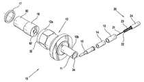
- FIG. 1 is an exploded perspective view of the coaxial connector.
- FIG. 2 is a cross-sectional view of the coaxial connector before cable insertion and crimping.
- FIG. 3 is a cross-sectional view of the coaxial connector including a terminated cable.
- FIG. 1 shows a coaxial cable connector 10 having an electrically conductive outer shell 12 comprising a mating section 12 a and a cylindrical sleeve 12 b.
- the mating section 12 a has a centrally located signal pin 15 surrounded by a dielectric 18 .
- An retaining ring 17 is positioned between the outer shell 12 and the dielectric 18 .
- the mating section 12 a may optionally comprise a fastener (not shown) that surrounds the conductive outer shell 12 , such as an internally threaded nut, designed to secure a complimentary receptacle to the mating section 12 a of the end connector 10 .
- the cylindrical sleeve 12 b has a cable receiving end 34 and an annular projection 11 .
- the cylindrical sleeve 12 b receives a coaxial cable 20 for termination within the connector 10 .
- the coaxial cable 20 shown in FIG. 1, has a center conductor 21 for transmitting a signal.
- the center conductor 21 is a solid or stranded wire that is centrally located within a dielectric 22 .
- An outer conductor 23 or shield surrounds the dielectric 22 .
- the outer conductor 23 generally comprises a pliant wire braid that may be woven over a foil sheath.
- the outer conductor 23 encircling the cylindrical dielectric 22 , is encased within a protective jacket 24 .
- the conductive outer shell 12 has a mating end 32 and a cable receiving end 34 disposed opposite the mating end 32 .
- An outer surface 36 extends from the mating end 32 to the cable receiving end 34 .
- the conductive outer shell 12 consists mainly of a mating section 12 a and a cylindrical sleeve 12 b. Within the mating section 12 a, the outer surface 36 is contoured to have raised portions 40 and recessed portions 42 disposed therebetween. Moving rearward from the mating section 12 a, an annular ridge 44 is disposed about the outer surface 36 rearward of the raised portion 40 .
- the cylindrical sleeve 12 b is disposed between the annular ridge 44 and the cable receiving end 34 .
- the cylindrical sleeve 12 b consists of a generally tubular section having a cylindrical sleeve inner surface 54 and a cylindrical sleeve outer surface 56 .
- An annular projection 11 is disposed around the cylindrical sleeve outer surface 56 at the cable receiving end 34 .
- the annular projection 11 is shown here as having a generally rectangular cross section it could have other geometrical configurations either on the outer surface 56 or the inner surface 54 that may have a similar function as will be described in greater detail below.
- the outer surface 36 has been described with a certain contour, that contour may be varied depending on size constraints and securing requirements of a particular application.
- the conductive outer shell 12 has a receptacle receiving portion 46 disposed along an inner surface 38 .
- the inner surface 38 extends from the mating end 32 to the cable receiving end 34 .
- a ring receiving portion 48 is located along the inner surface 38 rearward of receptacle receiving portion 46 and has a slightly smaller inner diameter than the receptacle receiving portion 46 .
- a dielectric receiving portion 50 is located rear of the ring receiving portion 48 and has a slightly smaller diameter than the ring receiving portion 48 .
- the dielectric receiving portion 50 ends at a rear wall 52 that connects with a cylindrical sleeve inner surface 54 .
- the cylindrical sleeve inner surface 54 is generally cylindrical and has a relatively smaller diameter than the dielectric receiving portion 50 .
- the cylindrical sleeve inner surface 54 extends from the rear wall 52 back to the cable receiving end 34 .
- a dielectric 60 is located within the dielectric receiving portion 50 at the mating end 32 of the connector 10 and has a diameter smaller than the inner surface 38 .
- the dielectric 60 extends to the rear wall 52 .
- the receptacle guide 60 has an inner receptacle receiving portion 58 .
- a signal pin receiving portion 62 is located within the dielectric 60 is open its rear end and extends to an insulative cylinder receiving portion 84 .
- Located on the signal pin receiving portion 62 is an annular stop wall 64 that transitioning to the larger circumferencial area of the insulative cylinder receiving portion 84 .
- the signal pin 15 is centrally located within the inner receptacle receiving portion 58 .
- the signal pin 15 has a coupling portion 15 a and a signal pin body 15 b.
- the coupling portion 15 a of the signal pin 15 extends to a wall 16 of the signal pin body 15 b.
- the signal pin body 15 b is hollow and has a larger diameter than the coupling portion 15 a.
- An insulative cylinder 14 has an insulative cylinder inner surface 72 , and insulative cylinder outer surface 66 extending between first and second ends 68 , 70 , respectively.
- the insulative cylinder inner surface 72 has a diameter smaller than the diameter of the insulative cylinder outer surface 66 .
- the diameter of the insulative cylinder outer surface 66 is smaller than the cylindrical sleeve inner surface 54 such that a small clearance exists between the insulative cylinder outer surface 66 and the cylindrical sleeve inner surface 54 .
- the insulative cylinder first end 68 is positioned adjacent to the signal pin body 15 b.
- the insulative cylinder second end 70 is positioned adjacent a conductive ferrule 13 .
- the ferrule 13 is generally cylindrical and has a ferrule outer surface 74 , a ferrule inner surface 76 , extending between first and second ends 78 , 80 , respectively.
- the ferrule inner surface 76 has a diameter smaller than the ferrule outer surface 74 , but larger than the insulative cylinder inner surface 72 .
- the ferrule outer surface 74 has a diameter which is smaller than the inner diameter of the cylindrical sleeve inner surface 54 , but slightly larger than the insulative cylinder outer surface 66 such that the clearance 19 between the ferrule outer surface 74 and the cylindrical sleeve inner surface 54 is slightly smaller than between the insulative cylinder 14 and the inner diameter 54 .
- the ferrule first end 78 is adjacent to the insulative cylinder second end 70 and extends to the cable receiving end 34 such that the ferrule second end 80 is positioned slightly forward within the annular projection 11 near the cable receiving end 34 .
- Termination of the coaxial cable 20 and assembly of the connector 10 will now be described in greater detail with reference to FIGS. 3 and 4.
- First the dielectric 60 is loaded into the mating section 12 a from the mating end 32 until it engages the rear wall 52 .
- the retaining ring 17 is secured in the receiving portion 48 to retain the dielectric 60 .
- a conventional tool is used to strip one end of the coaxial cable 20 as best shown in FIG. 1.
- the protective jacket 24 of the coaxial cable 20 is removed to expose the outer conductor 23 .
- a portion of the outer conductor 23 and a smaller portion of the dielectric 22 are 30 stripped away to expose the center conductor 21 .
- the ferrule 13 is positioned over the protective jacket 24 behind the exposed outer conductor 23 .
- the outer conductor 23 is then folded back over the ferrule 13 as best shown in FIG. 3.
- the insulative cylinder 14 is positioned over the section of the coaxial cable its dielectric 22 exposed behind.
- the center conductor 21 is received in the signal pin body 15 b and terminates behind wall 16 . Termination of the center conductor 21 to the signal pin 15 may be accomplished by crimping or other suitable means.
- the terminated pin 15 , insulative cylinder 14 , ferrule 13 and cable 20 subassembly is then inserted into the conductive outer shell 12 from the cable receiving end 34 until the pin body 15 b engages the annular stop wall 64 .
- the outer conductor 23 is received in a clearance 19 between the ferrule 13 and the inner surface 54 .
- a conventional crimping die such as a hex die (not shown) is then applied to the cylindrical sleeve 12 b to secure the coaxial cable 20 inside the connector 10 as best shown in FIG. 3. Because the annular projection 11 at the rear of the cylindrical sleeve 12 b has a larger external diameter compared to the balance of the cylindrical sleeve 12 b, as the cylindrical sleeve 12 b is crimped, the die will first contact the annular projection 11 . As the crimp is applied, the annular projection 11 is forced to roll inward and toward the mating end 32 of the conductive outer shell 12 .
- the cable receiving end 34 of the cylindrical sleeve 12 b has post crimp diameter which is slightly smaller than the balance of the cylindrical sleeve 12 b.
- the internal deformation of the cylindrical sleeve 12 b behind the ferrule 13 causes the internal components including the ferrule 13 , the insulative cylinder 14 , and the signal pin 15 , to be biased forward.
- the forward biased internal components, as well as the outer conductor 23 are locked in place by the internal surface of the annular projection 11 at the rear of the cylindrical sleeve 12 b.
- the cylindrical sleeve 12 b is compressed to eliminate the clearance 19 between the ferrule 13 and the cylindrical sleeve 12 b, securing the outer conductor 23 between the ferrule outer surface 74 and the cylindrical sleeve inner surface 54 .
- the major components are advantageously biased and retained in the conductive outer shell 12 by a single crimping action.
Landscapes
- Coupling Device And Connection With Printed Circuit (AREA)
Abstract
Description
- The present invention relates to coaxial cable connectors and, more particularly, to a coaxial connector having an improved crimp section.
- Coaxial cable connectors are commonly used to terminate coaxial cables. These connectors typically include a conductive outer shell comprising a mating section, a signal pin and a cylindrical sleeve that receives and mechanically secures a stripped end of a coaxial cable. The coaxial cable has a center conductor for transmitting a signal. The center conductor is surrounded by a dielectric. An outer ground or shield conductor in the form of a pliant wire braid encircles the dielectric. The outer conductor is encased in a protective jacket.
- To secure the coaxial cable in the connector, a stripped end of the coaxial cable is inserted into a receiving end of the cylindrical sleeve. The exposed center conductor is electrically connected to the signal pin contained within the connector. As the coaxial cable is inserted into the cylindrical sleeve, an inner tubular member, that may comprise raised barbs, is forced between the dielectric and the outer conductor of the coaxial cable. The outer conductor is received in a space between the cylindrical sleeve and the inner tubular member and may be folded back over the end of the protective jacket. This method and arrangement is disclosed in U.S. Pat. No. 5,499,934 issued to Jacobsen et al. and U.S. Pat. No. 5,525,076 issued to Down. A conventional crimping tool is then used to apply a crimp to the outside of the cylindrical sleeve securing the outer conductor jacket of the coaxial cable between the inner tubular member and the cylindrical sleeve.
- A known alternative method for securing a coaxial cable in a connector is commonly used when larger connectors terminate smaller coaxial cables. In this method, a ferrule and an insulative cylinder, respectively, are positioned over the stripped coaxial cable before insertion into the cylindrical sleeve. The exposed center conductor is electrically connected to the signal pin within the connector. The outer conductor of the coaxial cable is then folded back and over the ferrule so that the outer conductor is received in a space between the cylindrical sleeve and the ferrule when the coaxial cable is inserted into the cylindrical sleeve. A conventional crimping tool is then used to apply a crimp along the outside diameter of the cylindrical sleeve to secure the outer conductor jacket of the coaxial cable between the ferrule and the cylindrical sleeve.
- In these connectors, a compressive force applied by the crimp secures the internal components of the connector. This retention alone, however, is inadequate when external pulling forces are applied to the coaxial cable. For example, when an external force is exerted on the coaxial cable in a direction opposite from the connector body, the compressive forces are unable to prevent outward movement of the internal components. When the internal components become displaced, the integrity of the connector is jeopardized. Gaps created between the internal components also allow moisture and other foreign matter to enter the connector and may result in pin stubbing upon mating, further deteriorating the electrical performance of the connector.
- It is therefore desirable to develop a coaxial connector with a rigid construction that improves coaxial cable retention and electrical performance by providing additional physical restraint of the internal components of the coaxial connector.
- An object of the present invention is to develop an improved crimp section for a coaxial cable connector. This and other objects of the invention are achieved by a coaxial connector having a conductive outer shell comprising a mating section and a cylindrical sleeve. The cylindrical sleeve has a cable receiving end for receiving a cable, at least one ferrule located inside the cylindrical sleeve and an annular projection positioned on the cable receiving end of the cylindrical sleeve. The annular projection has a larger external diameter than the cylindrical sleeve. When a crimping die is applied to the cylindrical sleeve, the crimping die first contacts the annular projection, causing the annular projection to roll inward and toward the -mating section of the conductive outer shell to securely forward bias the cable and ferrule within the cylindrical sleeve.
- The invention will now be described by way of example with reference to the accompanying figures in which:
- FIG. 1 is an exploded perspective view of the coaxial connector.
- FIG. 2 is a cross-sectional view of the coaxial connector before cable insertion and crimping.
- FIG. 3 is a cross-sectional view of the coaxial connector including a terminated cable.
- FIG. 1 shows a
coaxial cable connector 10 having an electrically conductiveouter shell 12 comprising amating section 12 a and acylindrical sleeve 12 b. Themating section 12 a has a centrally locatedsignal pin 15 surrounded by a dielectric 18. Anretaining ring 17 is positioned between theouter shell 12 and the dielectric 18. Themating section 12 a may optionally comprise a fastener (not shown) that surrounds the conductiveouter shell 12, such as an internally threaded nut, designed to secure a complimentary receptacle to themating section 12 a of theend connector 10. Thecylindrical sleeve 12 b has acable receiving end 34 and anannular projection 11. Thecylindrical sleeve 12 b receives acoaxial cable 20 for termination within theconnector 10. Thecoaxial cable 20, shown in FIG. 1, has acenter conductor 21 for transmitting a signal. Thecenter conductor 21 is a solid or stranded wire that is centrally located within a dielectric 22. Anouter conductor 23 or shield surrounds the dielectric 22. Theouter conductor 23 generally comprises a pliant wire braid that may be woven over a foil sheath. Theouter conductor 23, encircling the cylindrical dielectric 22, is encased within aprotective jacket 24. - Each of the major components will now be described in greater detail with reference to FIGS. 1 and 2. As shown in FIG. 2, the conductive
outer shell 12 has amating end 32 and acable receiving end 34 disposed opposite themating end 32. Anouter surface 36 extends from themating end 32 to thecable receiving end 34. The conductiveouter shell 12 consists mainly of amating section 12 a and acylindrical sleeve 12 b. Within themating section 12 a, theouter surface 36 is contoured to have raisedportions 40 and recessedportions 42 disposed therebetween. Moving rearward from themating section 12 a, anannular ridge 44 is disposed about theouter surface 36 rearward of the raisedportion 40. - The
cylindrical sleeve 12 b is disposed between theannular ridge 44 and thecable receiving end 34. Thecylindrical sleeve 12 b consists of a generally tubular section having a cylindrical sleeveinner surface 54 and a cylindrical sleeveouter surface 56. Anannular projection 11 is disposed around the cylindrical sleeveouter surface 56 at thecable receiving end 34. It should be understood by those reasonably skilled in the art that while theannular projection 11 is shown here as having a generally rectangular cross section it could have other geometrical configurations either on theouter surface 56 or theinner surface 54 that may have a similar function as will be described in greater detail below. Also, it should be understood by those reasonably skilled in the art that while theouter surface 36 has been described with a certain contour, that contour may be varied depending on size constraints and securing requirements of a particular application. - Beginning once again at the
mating end 32 in FIG. 2, the conductiveouter shell 12 has areceptacle receiving portion 46 disposed along aninner surface 38. Theinner surface 38 extends from themating end 32 to thecable receiving end 34. Aring receiving portion 48 is located along theinner surface 38 rearward ofreceptacle receiving portion 46 and has a slightly smaller inner diameter than thereceptacle receiving portion 46. A dielectric receivingportion 50 is located rear of thering receiving portion 48 and has a slightly smaller diameter than thering receiving portion 48. The dielectric receivingportion 50 ends at arear wall 52 that connects with a cylindrical sleeveinner surface 54. The cylindrical sleeveinner surface 54 is generally cylindrical and has a relatively smaller diameter than the dielectric receivingportion 50. The cylindrical sleeveinner surface 54 extends from therear wall 52 back to thecable receiving end 34. - A dielectric 60 is located within the dielectric receiving
portion 50 at themating end 32 of theconnector 10 and has a diameter smaller than theinner surface 38. The dielectric 60 extends to therear wall 52. Thereceptacle guide 60 has an innerreceptacle receiving portion 58. A signalpin receiving portion 62 is located within the dielectric 60 is open its rear end and extends to an insulativecylinder receiving portion 84. Located on the signalpin receiving portion 62 is anannular stop wall 64 that transitioning to the larger circumferencial area of the insulativecylinder receiving portion 84. - The
signal pin 15 is centrally located within the innerreceptacle receiving portion 58. Thesignal pin 15 has acoupling portion 15 a and asignal pin body 15 b. Thecoupling portion 15 a of thesignal pin 15 extends to awall 16 of thesignal pin body 15 b. Thesignal pin body 15 b is hollow and has a larger diameter than thecoupling portion 15 a. - An
insulative cylinder 14 has an insulative cylinderinner surface 72, and insulative cylinderouter surface 66 extending between first and second ends 68, 70, respectively. The insulative cylinderinner surface 72 has a diameter smaller than the diameter of the insulative cylinderouter surface 66. The diameter of the insulative cylinderouter surface 66 is smaller than the cylindrical sleeveinner surface 54 such that a small clearance exists between the insulative cylinderouter surface 66 and the cylindrical sleeveinner surface 54. The insulative cylinderfirst end 68 is positioned adjacent to thesignal pin body 15 b. The insulative cylindersecond end 70 is positioned adjacent aconductive ferrule 13. - The
ferrule 13 is generally cylindrical and has a ferruleouter surface 74, a ferruleinner surface 76, extending between first and second ends 78, 80, respectively. The ferruleinner surface 76 has a diameter smaller than the ferruleouter surface 74, but larger than the insulative cylinderinner surface 72. The ferruleouter surface 74 has a diameter which is smaller than the inner diameter of the cylindrical sleeveinner surface 54, but slightly larger than the insulative cylinderouter surface 66 such that theclearance 19 between the ferruleouter surface 74 and the cylindrical sleeveinner surface 54 is slightly smaller than between theinsulative cylinder 14 and theinner diameter 54. The ferrulefirst end 78 is adjacent to the insulative cylindersecond end 70 and extends to thecable receiving end 34 such that the ferrulesecond end 80 is positioned slightly forward within theannular projection 11 near thecable receiving end 34. - Termination of the
coaxial cable 20 and assembly of theconnector 10 will now be described in greater detail with reference to FIGS. 3 and 4. First the dielectric 60 is loaded into themating section 12 a from themating end 32 until it engages therear wall 52. The retainingring 17 is secured in the receivingportion 48 to retain the dielectric 60. - To prepare the
coaxial cable 20 for installation in theend connector 10, a conventional tool is used to strip one end of thecoaxial cable 20 as best shown in FIG. 1. Theprotective jacket 24 of thecoaxial cable 20 is removed to expose theouter conductor 23. A portion of theouter conductor 23 and a smaller portion of the dielectric 22 are 30 stripped away to expose thecenter conductor 21. - The
ferrule 13 is positioned over theprotective jacket 24 behind the exposedouter conductor 23. Theouter conductor 23 is then folded back over theferrule 13 as best shown in FIG. 3. Theinsulative cylinder 14 is positioned over the section of the coaxial cable its dielectric 22 exposed behind. Thecenter conductor 21 is received in thesignal pin body 15 b and terminates behindwall 16. Termination of thecenter conductor 21 to thesignal pin 15 may be accomplished by crimping or other suitable means. The terminatedpin 15,insulative cylinder 14,ferrule 13 andcable 20 subassembly is then inserted into the conductiveouter shell 12 from thecable receiving end 34 until thepin body 15 b engages theannular stop wall 64. Theouter conductor 23 is received in aclearance 19 between theferrule 13 and theinner surface 54. - A conventional crimping die, such as a hex die (not shown) is then applied to the
cylindrical sleeve 12 b to secure thecoaxial cable 20 inside theconnector 10 as best shown in FIG. 3. Because theannular projection 11 at the rear of thecylindrical sleeve 12 b has a larger external diameter compared to the balance of thecylindrical sleeve 12 b, as thecylindrical sleeve 12 b is crimped, the die will first contact theannular projection 11. As the crimp is applied, theannular projection 11 is forced to roll inward and toward themating end 32 of the conductiveouter shell 12. As a result, thecable receiving end 34 of thecylindrical sleeve 12 b has post crimp diameter which is slightly smaller than the balance of thecylindrical sleeve 12 b. The internal deformation of thecylindrical sleeve 12 b behind theferrule 13 causes the internal components including theferrule 13, theinsulative cylinder 14, and thesignal pin 15, to be biased forward. The forward biased internal components, as well as theouter conductor 23 are locked in place by the internal surface of theannular projection 11 at the rear of thecylindrical sleeve 12 b. - As the die continues to crimp the
cylindrical sleeve 12 b, thecylindrical sleeve 12 b is compressed to eliminate theclearance 19 between theferrule 13 and thecylindrical sleeve 12 b, securing theouter conductor 23 between the ferruleouter surface 74 and the cylindrical sleeveinner surface 54. The major components are advantageously biased and retained in the conductiveouter shell 12 by a single crimping action. - While the present invention has been described in connection with the illustrated embodiments, it will be appreciated and understood that modifications may be made without departing from the true spirit and scope of the invention. For example, the annular projection could be positioned on the cylindrical sleeve inner surface and a similar effect may be achieved. It is, therefore, intended that the foregoing description be regarded as illustrative rather than limiting, and that the scope of the invention is given by the appended claims together with their full range of equivalents.
Claims (11)
Priority Applications (1)
| Application Number | Priority Date | Filing Date | Title |
|---|---|---|---|
| US10/116,242 US6808416B2 (en) | 2002-04-04 | 2002-04-04 | Coaxial cable connector |
Applications Claiming Priority (1)
| Application Number | Priority Date | Filing Date | Title |
|---|---|---|---|
| US10/116,242 US6808416B2 (en) | 2002-04-04 | 2002-04-04 | Coaxial cable connector |
Publications (2)
| Publication Number | Publication Date |
|---|---|
| US20030190840A1 true US20030190840A1 (en) | 2003-10-09 |
| US6808416B2 US6808416B2 (en) | 2004-10-26 |
Family
ID=28673927
Family Applications (1)
| Application Number | Title | Priority Date | Filing Date |
|---|---|---|---|
| US10/116,242 Expired - Fee Related US6808416B2 (en) | 2002-04-04 | 2002-04-04 | Coaxial cable connector |
Country Status (1)
| Country | Link |
|---|---|
| US (1) | US6808416B2 (en) |
Cited By (3)
| Publication number | Priority date | Publication date | Assignee | Title |
|---|---|---|---|---|
| US20040203283A1 (en) * | 2003-04-09 | 2004-10-14 | Insert Enterprise Co., Ltd. | Module type mini bnc connector |
| US20170323706A1 (en) * | 2016-05-04 | 2017-11-09 | Md Elektronik Gmbh | Cable having a pluggable connector |
| CN114927908A (en) * | 2022-05-30 | 2022-08-19 | 德尔特微波电子(南京)有限公司 | SMA cable connector with ultra-small bending radius |
Families Citing this family (5)
| Publication number | Priority date | Publication date | Assignee | Title |
|---|---|---|---|---|
| JP5454187B2 (en) * | 2009-03-27 | 2014-03-26 | 日立金属株式会社 | Cable fixing method and cable connection part |
| JP5319817B1 (en) * | 2012-04-06 | 2013-10-16 | ファナック株式会社 | Motor structure with soldered terminals soldered to connectors or terminal blocks |
| US9419349B2 (en) | 2014-10-10 | 2016-08-16 | Tyco Electronics Brasil Ltda. | Coaxial cable connector having a fastener and anti-rotation projections |
| KR102447286B1 (en) * | 2021-04-19 | 2022-09-26 | 주식회사 센서뷰 | adapter for cable |
| US11637388B2 (en) | 2021-09-17 | 2023-04-25 | Aptiv Technologies Limited | Ferrule for a coaxial cable terminal having overlapping crimp wings |
Citations (1)
| Publication number | Priority date | Publication date | Assignee | Title |
|---|---|---|---|---|
| US6471545B1 (en) * | 1993-05-14 | 2002-10-29 | The Whitaker Corporation | Coaxial connector for coaxial cable having a corrugated outer conductor |
Family Cites Families (14)
| Publication number | Priority date | Publication date | Assignee | Title |
|---|---|---|---|---|
| US3297979A (en) * | 1965-01-05 | 1967-01-10 | Amp Inc | Crimpable coaxial connector |
| US3355698A (en) | 1965-04-28 | 1967-11-28 | Amp Inc | Electrical connector |
| US3363222A (en) * | 1965-12-29 | 1968-01-09 | Amp Inc | Coaxial patchcord assembly |
| US3539709A (en) * | 1968-11-04 | 1970-11-10 | Itt | Sealing crimp ring for coaxial connector |
| JPH0341434Y2 (en) * | 1986-09-17 | 1991-08-30 | ||
| US4772222A (en) * | 1987-10-15 | 1988-09-20 | Amp Incorporated | Coaxial LMC connector |
| US5073129A (en) | 1989-06-12 | 1991-12-17 | John Mezzalingua Assoc. Inc. | Coaxial cable end connector |
| US4990106A (en) | 1989-06-12 | 1991-02-05 | John Mezzalingua Assoc. Inc. | Coaxial cable end connector |
| US4966560A (en) * | 1989-09-07 | 1990-10-30 | Calcomp Inc. | Coaxial connector plug using a center conductor sleeve and single point crimping |
| US5113474A (en) | 1990-03-13 | 1992-05-12 | Optical Fiber Technologies, Inc. | Method and apparatus for mechanical connector assembly |
| US5141451A (en) | 1991-05-22 | 1992-08-25 | Gilbert Engineering Company, Inc. | Securement means for coaxial cable connector |
| US5338225A (en) | 1993-05-27 | 1994-08-16 | Cabel-Con, Inc. | Hexagonal crimp connector |
| US5525076A (en) | 1994-11-29 | 1996-06-11 | Gilbert Engineering | Longitudinally compressible coaxial cable connector |
| US5860833A (en) | 1997-05-01 | 1999-01-19 | Trompeter Electronics, Inc. | Electrical connector having a probe positionable between a pair of spaced positions |
-
2002
- 2002-04-04 US US10/116,242 patent/US6808416B2/en not_active Expired - Fee Related
Patent Citations (1)
| Publication number | Priority date | Publication date | Assignee | Title |
|---|---|---|---|---|
| US6471545B1 (en) * | 1993-05-14 | 2002-10-29 | The Whitaker Corporation | Coaxial connector for coaxial cable having a corrugated outer conductor |
Cited By (5)
| Publication number | Priority date | Publication date | Assignee | Title |
|---|---|---|---|---|
| US20040203283A1 (en) * | 2003-04-09 | 2004-10-14 | Insert Enterprise Co., Ltd. | Module type mini bnc connector |
| US6866543B2 (en) * | 2003-04-09 | 2005-03-15 | Insert Enterprise Co., Ltd. | Module type mini BNC connector |
| US20170323706A1 (en) * | 2016-05-04 | 2017-11-09 | Md Elektronik Gmbh | Cable having a pluggable connector |
| US10074462B2 (en) * | 2016-05-04 | 2018-09-11 | Md Elektronik Gmbh | Cable having a pluggable connector |
| CN114927908A (en) * | 2022-05-30 | 2022-08-19 | 德尔特微波电子(南京)有限公司 | SMA cable connector with ultra-small bending radius |
Also Published As
| Publication number | Publication date |
|---|---|
| US6808416B2 (en) | 2004-10-26 |
Similar Documents
| Publication | Publication Date | Title |
|---|---|---|
| US4593964A (en) | Coaxial electrical connector for multiple outer conductor coaxial cable | |
| US4553806A (en) | Coaxial electrical connector for multiple outer conductor coaxial cable | |
| US4377320A (en) | Coaxial connector | |
| US4619496A (en) | Coaxial plug and jack connectors | |
| US5429529A (en) | Structure for connecting shielded-cable end | |
| US5393244A (en) | Twist-on coaxial cable end connector with internal post | |
| US5352134A (en) | RF shielded coaxial cable connector | |
| US4813887A (en) | Electrical connector for multiple outer conductor coaxial cable | |
| US5456614A (en) | Coaxial cable end connector with signal seal | |
| US7635282B2 (en) | Coaxial cable shielding terminal with improved press-clamping portion | |
| JP3356301B2 (en) | Coaxial contact and method of connecting it to coaxial cable | |
| US4445745A (en) | Electrical connectors for coaxial and two-wire cables | |
| US5167520A (en) | Cup fit plug connector | |
| EP0175144A3 (en) | Direct-crimp coaxial cable connector | |
| US7217155B2 (en) | Compression connector for braided coaxial cable | |
| JPS6311751B2 (en) | ||
| US6753475B2 (en) | Shielding terminal for coaxial cable | |
| US4342496A (en) | Contact assembly incorporating retaining means | |
| US4583809A (en) | Electrical connector assembly having means for EMI shielding | |
| US6896549B2 (en) | Device for connecting coaxial conductors to a plug-in connector | |
| US3539709A (en) | Sealing crimp ring for coaxial connector | |
| GB2139018A (en) | Coaxial plug and jack connectors | |
| US6808416B2 (en) | Coaxial cable connector | |
| US6048227A (en) | Connector backshell | |
| US5730623A (en) | Matched impedance triax contact with grounded connector |
Legal Events
| Date | Code | Title | Description |
|---|---|---|---|
| AS | Assignment |
Owner name: Y-CONNECT INCORPORATED, PENNSYLVANIA Free format text: ASSIGNMENT OF ASSIGNORS INTEREST;ASSIGNORS:FEGLEY, JEFFREY J.;ENGLISH, JAMES;FETTEROLF, SR., JAMES;REEL/FRAME:012776/0915 Effective date: 20020403 |
|
| AS | Assignment |
Owner name: YAZAKI NORTH AMERICA, INC., MICHIGAN Free format text: MERGER;ASSIGNOR:Y-CONNECT, INCORPORATED;REEL/FRAME:014319/0345 Effective date: 20030328 |
|
| REMI | Maintenance fee reminder mailed | ||
| LAPS | Lapse for failure to pay maintenance fees | ||
| STCH | Information on status: patent discontinuation |
Free format text: PATENT EXPIRED DUE TO NONPAYMENT OF MAINTENANCE FEES UNDER 37 CFR 1.362 |
|
| FP | Lapsed due to failure to pay maintenance fee |
Effective date: 20081026 |