US20030190835A1 - Conduit retaining clip - Google Patents
Conduit retaining clip Download PDFInfo
- Publication number
- US20030190835A1 US20030190835A1 US10/116,623 US11662302A US2003190835A1 US 20030190835 A1 US20030190835 A1 US 20030190835A1 US 11662302 A US11662302 A US 11662302A US 2003190835 A1 US2003190835 A1 US 2003190835A1
- Authority
- US
- United States
- Prior art keywords
- compressor
- cable
- housing
- axis
- conduit
- Prior art date
- Legal status (The legal status is an assumption and is not a legal conclusion. Google has not performed a legal analysis and makes no representation as to the accuracy of the status listed.)
- Granted
Links
Images


Classifications
-
- H—ELECTRICITY
- H02—GENERATION; CONVERSION OR DISTRIBUTION OF ELECTRIC POWER
- H02G—INSTALLATION OF ELECTRIC CABLES OR LINES, OR OF COMBINED OPTICAL AND ELECTRIC CABLES OR LINES
- H02G15/00—Cable fittings
- H02G15/02—Cable terminations
- H02G15/04—Cable-end sealings
-
- H—ELECTRICITY
- H01—ELECTRIC ELEMENTS
- H01R—ELECTRICALLY-CONDUCTIVE CONNECTIONS; STRUCTURAL ASSOCIATIONS OF A PLURALITY OF MUTUALLY-INSULATED ELECTRICAL CONNECTING ELEMENTS; COUPLING DEVICES; CURRENT COLLECTORS
- H01R13/00—Details of coupling devices of the kinds covered by groups H01R12/70 or H01R24/00 - H01R33/00
- H01R13/58—Means for relieving strain on wire connection, e.g. cord grip, for avoiding loosening of connections between wires and terminals within a coupling device terminating a cable
- H01R13/59—Threaded ferrule or bolt operating in a direction parallel to the cable or wire
Definitions
- This invention relates to a clip for a power supply housing of a compressor canister.
- Compressors are typically mounted within a sealed housing structure, such as a shell.
- the housing structure receives a compressor pump unit and an electric motor for driving the compressor pump unit. Refrigerant flows within the compressor housing for cooling the electric motor.
- the motor requires a source of current to power its windings.
- One recent power supply for a sealed compressor communicates power to the electric motor from a removable cable located on the outside of the housing structure. The cable is connected to terminals that act as electrical contacts to carry the power to the electric motor within the housing structure.
- a protective cover such as a power supply housing, serves to create a barrier between the terminal ends and the environment.
- This power supply housing is attached to the compressor canister.
- the power supply housing may comprise two pieces: a terminal fence or wall that attaches to the compressor canister and a cover which connects to the terminal fence. This two-piece assembly permits an installer to make the terminal connections between the cable and the canister and then place the cover over the terminal fence.
- the terminal fence has a slot to permit the cable to pass through its wall.
- the slot is generally u-shaped to permit the cable to be quickly laid in the slot of the fence. This feature, however, also allows the cable to slip out of the slot or at least move somewhat after installation.
- a protective tube or conduit comprising a hollow cylinder may receive the cable and serve to seal the slot around the cable. This conduit may be secured axially along the cable's length but may also slip out of the U-shaped opening or move within the spring after installation.
- the invention comprises a compressor assembly.
- the assembly has a compressor pump unit and a motor powering the pump unit.
- a housing surrounds the compressor pump unit and the motor, providing a protective and sealed environment.
- a cable communicates electricity to the motor through electrical contacts on the housing. Protecting the contacts from the environment is a power supply housing.
- the power supply housing has a slot to receive the cable. This slot permits insertion of the cable into the housing along a first axis and also permits removal of the cable along a second axis transverse to the first axis.
- a clip serves to connect the cable to the housing and limit movement of the cable along the second axis.
- the compressor may have a conduit disposed around the cable to provide further protection of the cable and the electrical contacts.
- the conduit may comprise a threaded portion that mates with a nut. The conduit is inserted into the slot and the nut tightened around the slot and within the housing, thereby preventing the conduit from moving along the first axis outwardly of the slot.
- a lip may be formed around the slot.
- the clip may connect to this lip.
- the clip may comprise a ring having one leg that engages the lip and prevents movement of the cable along the second axis.
- more legs may be formed on the clip to better secure the clip to the lip of the slot.
- the legs of the clip may expand to permit the clip to be snapped onto the lip.
- a cover may be placed over the fence to provide additional protection for the electrical contacts of the compressor housing.
- a cable may be set into the slot of the power supply housing of the compressor.
- the cable is then secured to the power supply housing along a first axis.
- the cable is clipped to this housing to prevent movement of the cable along a second axis transverse to the first axis.
- the clip may attach to a conduit disposed around the cable. In this way, the cable is secured to the slot. Once secured in this fashion, an installer is then free to make the necessary terminal connections between the cable and the compressor motor without concern of having the cable slip out of the slot.
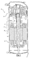
- FIG. 1 shows compressor housing, power supply housing, and cable.
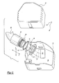
- FIG. 2 illustrates an exploded view of the power supply housing including cable, conduit, clip, nut and terminal connections.
- FIG. 2A shows a cross sectional view of the embodiment of FIG. 2.
- FIG. 3 illustrates the clip of FIGS. 2 and 3.
- FIG. 4 illustrates an alternative view of the clip of FIG. 3.
- FIG. 5 illustrates a cross sectional view of the clip placed over the lip of the fence of the cable housing of FIGS. 2 and 2A.
- FIG. 6 illustrates the placement of the clip on the lip of the fence of FIG. 5.
- FIG. 7 illustrates a perspective view of the clip assembled with conduit and nut.
- FIG. 8 illustrates another view of the embodiment of FIG. 7 with the cover removed.
- FIG. 9 illustrates the embodiment of FIG. 8 with cover snapped to the fence.
- FIG. 1 illustrates an environmental view of the invention, compressor 20 .
- compressor 20 comprises a compressor pump unit 21 and an electric motor 23 supported and protected by compressor housing 24 .
- the pump unit 21 is preferably a scroll compressor, as shown, but other sealed compressors will benefit from this invention.
- Power is supplied to compressor 20 and to motor therein by cable 28 , which may be connected to a source of electrical power.
- Power supply housing 32 is mounted to compressor housing 24 and provides protection for the electrical interface between cable 28 and the interior of compressor housing 24 .
- Housing 32 is preferably provided with terminal connections to the motor, and is preferably potted.
- the power supply housing interior may be generally as described in U.S. Pat. No. 6,290,528.
- wires 25 (shown schematically) connect housing 32 to motor 23 .
- Cable 28 is connected to wires 25 such as shown at 27 within housing 32 .
- FIG. 2 illustrates an exploded greatly simplified view of power supply housing 32 .
- power supply housing 32 comprises fence 36 and cover 40 .
- Fence 36 has slot 44 , which may be a u-shaped opening in fence 36 .
- Fence 36 comprises a wall with an interior room 38 where cable 28 connects to terminal ends 48 , which are the electrical contacts for supplying power to the motor.
- Cable 28 may be inserted along the x-axis or laid onto slot across the y-axis as a consequence of the u-shaped opening of slot 44 .
- cable 28 is also removable along both the x-axis and y-axis.
- the x-axis is orthogonal to the y-axis as shown here.
- conduit 56 Disposed around cable 28 is conduit 56 , which comprises a hollow cylinder to permit the insertion of cable 28 and to seal slot 44 from the environment. Threaded portion 60 is insertable through slot 44 . Nut 64 mates with threaded portion 60 inside the housing 32 to secure conduit 56 along the x-axis. Clip 52 provides the inventive aspect of this assembly by securing cable and conduit 56 along the y-axis.
- FIG. 2A better illustrates this inventive feature.
- This figure shows a cross-sectional view of the embodiment of FIG. 2.
- cable 28 and conduit are inserted through slot 44 .
- lip 68 Surrounding slot 44 is lip 68 , a protrusion formed on fence 36 .
- Nut 64 is tightened on threaded portion 60 of conduit 56 , preventing conduit 56 from moving along the x-axis.
- Clip 52 is disposed around both conduit 56 and cable 28 .
- leg 72 A of clip 52 contacts lip 68 of fence 36 , thereby limiting movement of conduit 56 and cable 28 along the y-axis.
- Clip 52 accordingly locks conduit 56 and cable 28 in place to reduce movement of cable 28 and protect the connection of terminals 48 . Accordingly, cable 28 and conduit 56 are secured along the y-axis.
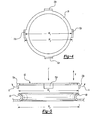
- FIG. 3 illustrates a close up view of the inventive clip 52 .
- Clip 52 comprises ring 76 having four legs, 72 A, 72 B, 72 C and 72 D.
- Clip 52 is made of a resilient material, such as steel.
- legs 72 A, 72 B, 72 C and 72 D are spaced radially about equal distance from each other along ring 76 .
- Legs 72 A and 72 C are also spaced apart an unflexed distance WI. Due to the resilient nature of the material used, legs 72 A and 72 C may expand to a distance W2 greater than W1.
- Leg 72 B and 72 D may share a similar relationship.
- clip 52 maybe snapped onto lip 68 by positioning clip 52 over lip 68 and moving clip 52 along the direction of arrow F, which is also along the x-axis.
- legs 72 B and 72 C contact lip 68 , they flex outward expanding from distance W1 to width W2.
- leg 72 D does not contact lip 68
- leg 72 A will contact lip 68 and thereby be displaced so that distance between leg 72 A and 72 D is greater than W1.
- lip 68 contacts leg 72 B pushing leg 72 B in the direction of arrow H while lip 68 contacts leg 72 C and pushes leg 72 C in the direction of arrow G.
- Leg 72 A also operates in the same manner.
- a ramped outer surface 69 of lip 68 facilitates the movement.
- legs 72 A, 72 B and 72 D of clip 52 apply force around lip 68 .
- the lip 72 A is not shown in FIG. 6, but as can be seen in FIG. 2A, it would directly block movement out of the slot.
- leg 72 C applies force in the direction of arrow I while leg 72 B applies force in the direction of arrow J.
- Clip 52 is thereby retained on lip 68 .
- leg 72 D is not in contact with lip 68 due to its placement over the opening of slot 44 . While only three legs operate to retain clip 52 onto lip 68 , a fourth leg offers the installer of clip 52 the convenience of an additional leg to align clip 52 on lip 68 and to ensure contact of a leg on lip.
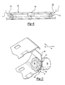
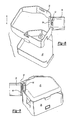
- FIG. 7 illustrates the assembly without a cover.
- Fence 36 is connected to conduit 56 with conduit 56 secured along two different directions by two connectors.
- Nut 64 secures conduit 56 along the x-axis while clip 52 secures conduit 56 along the y-axis.
- FIG. 8 shows the assembly with cover 40 .
- Fence 36 , clip 52 , conduit 56 , and nut 64 are also shown.
- Cover 40 may be snapped into fence 36 as known by inserting cover 40 into fence 36 along arrow K. Once these features have been secured and cable 28 connected to terminal ends 48 , cover 40 may be placed within fence 36 by moving cover 40 in the K direction, which is toward compressor pump unit 21 .
- FIG. 9 illustrates the final assembly with cover placed within fence 36 .
- conduit 56 is secured to fence 36 by clip 52 and nut 64 .
- Clip 52 connects conduit 56 to lip 68 of fence 36 .
Landscapes
- Compressor (AREA)
Abstract
Description
- This invention relates to a clip for a power supply housing of a compressor canister.
- Compressors are typically mounted within a sealed housing structure, such as a shell. The housing structure receives a compressor pump unit and an electric motor for driving the compressor pump unit. Refrigerant flows within the compressor housing for cooling the electric motor. The motor requires a source of current to power its windings. One recent power supply for a sealed compressor communicates power to the electric motor from a removable cable located on the outside of the housing structure. The cable is connected to terminals that act as electrical contacts to carry the power to the electric motor within the housing structure.
- In this type of compressor, a protective cover, such as a power supply housing, serves to create a barrier between the terminal ends and the environment. This power supply housing is attached to the compressor canister. The power supply housing may comprise two pieces: a terminal fence or wall that attaches to the compressor canister and a cover which connects to the terminal fence. This two-piece assembly permits an installer to make the terminal connections between the cable and the canister and then place the cover over the terminal fence.
- The terminal fence has a slot to permit the cable to pass through its wall. The slot is generally u-shaped to permit the cable to be quickly laid in the slot of the fence. This feature, however, also allows the cable to slip out of the slot or at least move somewhat after installation. Moreover, a protective tube or conduit comprising a hollow cylinder may receive the cable and serve to seal the slot around the cable. This conduit may be secured axially along the cable's length but may also slip out of the U-shaped opening or move within the spring after installation.
- A need therefore exists to better secure the cable and protective conduit to their proper location about the slot.
- The invention comprises a compressor assembly. As known, the assembly has a compressor pump unit and a motor powering the pump unit. A housing surrounds the compressor pump unit and the motor, providing a protective and sealed environment. A cable communicates electricity to the motor through electrical contacts on the housing. Protecting the contacts from the environment is a power supply housing. The power supply housing has a slot to receive the cable. This slot permits insertion of the cable into the housing along a first axis and also permits removal of the cable along a second axis transverse to the first axis. A clip serves to connect the cable to the housing and limit movement of the cable along the second axis.
- In addition, the compressor may have a conduit disposed around the cable to provide further protection of the cable and the electrical contacts. The conduit may comprise a threaded portion that mates with a nut. The conduit is inserted into the slot and the nut tightened around the slot and within the housing, thereby preventing the conduit from moving along the first axis outwardly of the slot.
- A lip may be formed around the slot. In this instance, the clip may connect to this lip. The clip may comprise a ring having one leg that engages the lip and prevents movement of the cable along the second axis. Preferably, more legs may be formed on the clip to better secure the clip to the lip of the slot. The legs of the clip may expand to permit the clip to be snapped onto the lip. A cover may be placed over the fence to provide additional protection for the electrical contacts of the compressor housing.
- Accordingly, a cable may be set into the slot of the power supply housing of the compressor. The cable is then secured to the power supply housing along a first axis. The cable is clipped to this housing to prevent movement of the cable along a second axis transverse to the first axis. The clip may attach to a conduit disposed around the cable. In this way, the cable is secured to the slot. Once secured in this fashion, an installer is then free to make the necessary terminal connections between the cable and the compressor motor without concern of having the cable slip out of the slot.
- The various features and advantages of this invention will become apparent to those skilled in the art from the following detailed description of the currently preferred embodiment. The drawings that accompany the detailed description can be briefly described as follows:
- FIG. 1 shows compressor housing, power supply housing, and cable.
- FIG. 2 illustrates an exploded view of the power supply housing including cable, conduit, clip, nut and terminal connections.
- FIG. 2A shows a cross sectional view of the embodiment of FIG. 2.
- FIG. 3 illustrates the clip of FIGS. 2 and 3.
- FIG. 4 illustrates an alternative view of the clip of FIG. 3.
- FIG. 5 illustrates a cross sectional view of the clip placed over the lip of the fence of the cable housing of FIGS. 2 and 2A.
- FIG. 6 illustrates the placement of the clip on the lip of the fence of FIG. 5.
- FIG. 7 illustrates a perspective view of the clip assembled with conduit and nut.
- FIG. 8 illustrates another view of the embodiment of FIG. 7 with the cover removed.
- FIG. 9 illustrates the embodiment of FIG. 8 with cover snapped to the fence.
- FIG. 1 illustrates an environmental view of the invention,
compressor 20. As known,compressor 20 comprises acompressor pump unit 21 and anelectric motor 23 supported and protected bycompressor housing 24. Thepump unit 21 is preferably a scroll compressor, as shown, but other sealed compressors will benefit from this invention. Power is supplied tocompressor 20 and to motor therein bycable 28, which may be connected to a source of electrical power.Power supply housing 32 is mounted tocompressor housing 24 and provides protection for the electrical interface betweencable 28 and the interior ofcompressor housing 24.Housing 32 is preferably provided with terminal connections to the motor, and is preferably potted. The power supply housing interior may be generally as described in U.S. Pat. No. 6,290,528. As shown, wires 25 (shown schematically) connecthousing 32 tomotor 23.Cable 28 is connected towires 25 such as shown at 27 withinhousing 32. - FIG. 2 illustrates an exploded greatly simplified view of
power supply housing 32. As shown from this view,power supply housing 32 comprisesfence 36 andcover 40.Fence 36 hasslot 44, which may be a u-shaped opening infence 36.Fence 36 comprises a wall with an interior room 38 wherecable 28 connects to terminal ends 48, which are the electrical contacts for supplying power to the motor.Cable 28 may be inserted along the x-axis or laid onto slot across the y-axis as a consequence of the u-shaped opening ofslot 44. In addition,cable 28 is also removable along both the x-axis and y-axis. The x-axis is orthogonal to the y-axis as shown here. - Disposed around
cable 28 isconduit 56, which comprises a hollow cylinder to permit the insertion ofcable 28 and to sealslot 44 from the environment. Threadedportion 60 is insertable throughslot 44.Nut 64 mates with threadedportion 60 inside thehousing 32 to secureconduit 56 along the x-axis.Clip 52 provides the inventive aspect of this assembly by securing cable andconduit 56 along the y-axis. - FIG. 2A better illustrates this inventive feature. This figure shows a cross-sectional view of the embodiment of FIG. 2. As shown,
cable 28 and conduit are inserted throughslot 44. Surroundingslot 44 islip 68, a protrusion formed onfence 36.Nut 64 is tightened on threadedportion 60 ofconduit 56, preventingconduit 56 from moving along the x-axis.Clip 52 is disposed around bothconduit 56 andcable 28. In addition, leg 72A ofclip 52contacts lip 68 offence 36, thereby limiting movement ofconduit 56 andcable 28 along the y-axis.Clip 52 accordingly locksconduit 56 andcable 28 in place to reduce movement ofcable 28 and protect the connection ofterminals 48. Accordingly,cable 28 andconduit 56 are secured along the y-axis. - FIG. 3 illustrates a close up view of the
inventive clip 52.Clip 52 comprisesring 76 having four legs, 72A, 72B, 72C and 72D.Clip 52 is made of a resilient material, such as steel. As shown in FIG. 4, legs 72A, 72B, 72C and 72D are spaced radially about equal distance from each other alongring 76. Legs 72A and 72C are also spaced apart an unflexed distance WI. Due to the resilient nature of the material used, legs 72A and 72C may expand to a distance W2 greater than W1. Leg 72B and 72D may share a similar relationship. - As shown in FIG. 5,
clip 52 maybe snapped ontolip 68 by positioningclip 52 overlip 68 and movingclip 52 along the direction of arrow F, which is also along the x-axis. As legs 72B and72 C contact lip 68, they flex outward expanding from distance W1 to width W2. While leg 72D does not contactlip 68, leg 72A will contactlip 68 and thereby be displaced so that distance between leg 72A and 72D is greater than W1. For example,lip 68 contacts leg 72B pushing leg 72B in the direction of arrow H whilelip 68 contacts leg 72C and pushes leg 72C in the direction of arrow G. Leg 72A also operates in the same manner. As can be seen, a rampedouter surface 69 oflip 68 facilitates the movement. - As shown in FIG. 6, once
clip 52 is placed completely onlip 68, legs 72A, 72B and 72D ofclip 52 apply force aroundlip 68. The lip 72A is not shown in FIG. 6, but as can be seen in FIG. 2A, it would directly block movement out of the slot. For example, leg 72C applies force in the direction of arrow I while leg 72B applies force in the direction ofarrow J. Clip 52 is thereby retained onlip 68. In both of these figures, it should be noted that leg 72D is not in contact withlip 68 due to its placement over the opening ofslot 44. While only three legs operate to retainclip 52 ontolip 68, a fourth leg offers the installer ofclip 52 the convenience of an additional leg to alignclip 52 onlip 68 and to ensure contact of a leg on lip. - FIG. 7 illustrates the assembly without a cover.
Fence 36 is connected toconduit 56 withconduit 56 secured along two different directions by two connectors.Nut 64 securesconduit 56 along the x-axis whileclip 52 securesconduit 56 along the y-axis. - FIG. 8 shows the assembly with
cover 40.Fence 36,clip 52,conduit 56, andnut 64 are also shown.Cover 40 may be snapped intofence 36 as known by insertingcover 40 intofence 36 along arrow K. Once these features have been secured andcable 28 connected to terminal ends 48, cover 40 may be placed withinfence 36 by movingcover 40 in the K direction, which is towardcompressor pump unit 21. - FIG. 9 illustrates the final assembly with cover placed within
fence 36. As shown,conduit 56 is secured tofence 36 byclip 52 andnut 64.Clip 52 connectsconduit 56 tolip 68 offence 36. - The aforementioned description is exemplary rather that limiting. Many modifications and variations of the present invention are possible in light of the above teachings. The preferred embodiments of this invention have been disclosed. However, one of ordinary skill in the art would recognize that certain modifications would come within the scope of this invention. Hence, within the scope of the appended claims, the invention may be practiced otherwise than as specifically described. For this reason the following claims should be studied to determine the true scope and content of this invention.
Claims (15)
Priority Applications (1)
| Application Number | Priority Date | Filing Date | Title |
|---|---|---|---|
| US10/116,623 US6776654B2 (en) | 2002-04-04 | 2002-04-04 | Conduit retaining clip |
Applications Claiming Priority (1)
| Application Number | Priority Date | Filing Date | Title |
|---|---|---|---|
| US10/116,623 US6776654B2 (en) | 2002-04-04 | 2002-04-04 | Conduit retaining clip |
Publications (2)
| Publication Number | Publication Date |
|---|---|
| US20030190835A1 true US20030190835A1 (en) | 2003-10-09 |
| US6776654B2 US6776654B2 (en) | 2004-08-17 |
Family
ID=28674033
Family Applications (1)
| Application Number | Title | Priority Date | Filing Date |
|---|---|---|---|
| US10/116,623 Expired - Fee Related US6776654B2 (en) | 2002-04-04 | 2002-04-04 | Conduit retaining clip |
Country Status (1)
| Country | Link |
|---|---|
| US (1) | US6776654B2 (en) |
Cited By (2)
| Publication number | Priority date | Publication date | Assignee | Title |
|---|---|---|---|---|
| US20120282124A1 (en) * | 2010-11-10 | 2012-11-08 | Emerson Climate Technologies, Inc. | Compressor and enclosure assembly for electrical components |
| US9480177B2 (en) | 2012-07-27 | 2016-10-25 | Emerson Climate Technologies, Inc. | Compressor protection module |
Families Citing this family (1)
| Publication number | Priority date | Publication date | Assignee | Title |
|---|---|---|---|---|
| USD915367S1 (en) * | 2018-11-24 | 2021-04-06 | Joseph H Abrams | Phone ear spacer |
Family Cites Families (40)
| Publication number | Priority date | Publication date | Assignee | Title |
|---|---|---|---|---|
| US4059325A (en) | 1976-12-13 | 1977-11-22 | General Electric Company | Terminal protection shield |
| US4151363A (en) * | 1976-12-20 | 1979-04-24 | Nichols Wayne L | Method and apparatus for joining electrical conductors to junction boxes |
| US4109992A (en) | 1977-08-05 | 1978-08-29 | Amp Incorporated | Connector for compressor header |
| US4227764A (en) | 1978-11-07 | 1980-10-14 | Bunker Ramo Corporation | Connector and adapter system |
| US4252394A (en) | 1979-05-16 | 1981-02-24 | Tecumseh Products Company | Hermetic compressor motor terminal |
| US4654470A (en) | 1983-10-31 | 1987-03-31 | Amp Incorporated | Raintight junction box |
| US4523798A (en) | 1983-11-03 | 1985-06-18 | Carrier Corporation | Connector block |
| US4584433A (en) | 1984-12-03 | 1986-04-22 | Emerson Electric Co. | Hermetic terminal assembly |
| US4712157A (en) | 1987-03-16 | 1987-12-08 | General Electric Company | Stud mounted non-metallic electric enclosure |
| US4827502A (en) | 1987-04-16 | 1989-05-02 | Reliance Comm/Tec Corporation | Environmentally protected housing for using central office protector modules outdoors |
| US4915638A (en) | 1988-04-29 | 1990-04-10 | Anthony Domian | Protective enclosure for electrical outlets |
| US4840547A (en) | 1988-08-10 | 1989-06-20 | Tecumseh Products Company | Compressor including protective cap for hermetic terminal |
| US4998891A (en) | 1988-11-04 | 1991-03-12 | Bresko Joseph R | Holder for maintaining electrical connections |
| JP2598130B2 (en) | 1989-05-24 | 1997-04-09 | ファナック株式会社 | Structure of motor with integral connector |
| IT1230237B (en) | 1989-06-08 | 1991-10-18 | Bull Hn Information Syst | HOOKING DEVICE FOR PRINTED CIRCUIT PLATE CONNECTORS. |
| US4921454A (en) | 1989-06-20 | 1990-05-01 | Amp Incorporated | Cluster block assembly |
| US4984973A (en) | 1990-03-21 | 1991-01-15 | Tecumseh Products Company | Hermetic motor compressor unit having a hermetic terminal with electrically insulating anti-tracking cap |
| US5035653A (en) | 1990-04-02 | 1991-07-30 | Emerson Electric Co. | Terminal block for a hermetic terminal assembly |
| US5145417A (en) | 1990-04-02 | 1992-09-08 | Emerson Electric Co. | Terminal block assembly for hermetic terminal structure |
| US5091821A (en) | 1990-04-23 | 1992-02-25 | Peyton Thomas B | Protective cover for electrical assembly unit |
| US5084596A (en) | 1990-06-04 | 1992-01-28 | The Lamson & Sessions Co. | Electrical box |
| US5145388A (en) | 1991-05-31 | 1992-09-08 | Amp Incorporated | Enclosure for crossconnect terminal block |
| US5129843A (en) | 1991-06-19 | 1992-07-14 | Emerson Electric Co. | Connector block for a terminal assembly |
| US5120237A (en) | 1991-07-22 | 1992-06-09 | Fussell Don L | Snap on cable connector |
| US5194012A (en) | 1991-07-30 | 1993-03-16 | Cairns James L | Spark-proof hostile environment connector |
| US5199898A (en) | 1991-09-23 | 1993-04-06 | Tecumseh Products Company | External terminal shield |
| US5252083A (en) | 1991-10-01 | 1993-10-12 | Correnti Giuseppe A | Electrical outlet safety cover |
| JP2528109Y2 (en) | 1991-11-27 | 1997-03-05 | 矢崎総業株式会社 | Connector assembly structure |
| US5173057A (en) | 1992-02-07 | 1992-12-22 | Tecumseh Products Company | Permanent protective cover |
| JP3020341B2 (en) | 1992-03-18 | 2000-03-15 | 松下冷機株式会社 | Airtight terminal protection cover |
| US5239129A (en) | 1992-04-06 | 1993-08-24 | Hubbell Incorporated | Housing for switched electrical receptacle or the like |
| US5244408A (en) | 1992-05-22 | 1993-09-14 | At&T Bell Laboratories | Terminal housing |
| JP2910457B2 (en) | 1992-09-11 | 1999-06-23 | 株式会社日立製作所 | Scroll fluid machine |
| US5272297A (en) | 1992-11-23 | 1993-12-21 | General Electric Company | Streamlined air conditioning disconnect switch |
| US5413502A (en) * | 1994-02-01 | 1995-05-09 | Wang; Tsan-Chi | Auto termination type electrical connector |
| US5430619A (en) | 1994-03-18 | 1995-07-04 | Lindenbaum Systems Design, Inc. | Terminal box |
| US5769659A (en) | 1995-12-13 | 1998-06-23 | Copeland Corporation | Plastic terminal box |
| WO1999043064A1 (en) * | 1998-02-19 | 1999-08-26 | Walker Systems, Inc. | Wire protection and storage grommet |
| US6290528B1 (en) | 1998-07-14 | 2001-09-18 | Carrier Corporation | Electric power supply connector for sealed compressor |
| US6248952B1 (en) * | 1999-03-15 | 2001-06-19 | Delphi Technologies, Inc. | Wiring protection dress for automotive electrical wiring extending between a splash shield and tubular conduits |
-
2002
- 2002-04-04 US US10/116,623 patent/US6776654B2/en not_active Expired - Fee Related
Cited By (6)
| Publication number | Priority date | Publication date | Assignee | Title |
|---|---|---|---|---|
| US20120282124A1 (en) * | 2010-11-10 | 2012-11-08 | Emerson Climate Technologies, Inc. | Compressor and enclosure assembly for electrical components |
| CN103201516A (en) * | 2010-11-10 | 2013-07-10 | 艾默生环境优化技术有限公司 | Compressor and enclosure assembly for electrical components |
| US9502873B2 (en) * | 2010-11-10 | 2016-11-22 | Emerson Climate Technologies, Inc. | Compressor and enclosure assembly for electrical components |
| US9480177B2 (en) | 2012-07-27 | 2016-10-25 | Emerson Climate Technologies, Inc. | Compressor protection module |
| US10028399B2 (en) | 2012-07-27 | 2018-07-17 | Emerson Climate Technologies, Inc. | Compressor protection module |
| US10485128B2 (en) | 2012-07-27 | 2019-11-19 | Emerson Climate Technologies, Inc. | Compressor protection module |
Also Published As
| Publication number | Publication date |
|---|---|
| US6776654B2 (en) | 2004-08-17 |
Similar Documents
| Publication | Publication Date | Title |
|---|---|---|
| US5683263A (en) | Coaxial cable connector with electromagnetic interference and radio frequency interference elimination | |
| US5766030A (en) | Cap type connector assembly for high-voltage cable | |
| EP2672117B1 (en) | Motor-driven compressor | |
| US20060071569A1 (en) | Stator end caps and methods for positioning the lead and exit ends of the stator windings | |
| EP0649212B1 (en) | Motor stator assembly and full-circumferential flow pump employing such motor stator assembly | |
| US6205644B1 (en) | Method of assembling an electric motor | |
| US20040231949A1 (en) | Direct method of terminating the ground coil terminal to coil housing | |
| EP1246346B1 (en) | AC generator having air port in slip ring cover | |
| JPH05280502A (en) | Electrohydraulic device for automobile | |
| US6315528B1 (en) | Terminal connection in small area of scroll compressor and method for carrying out same | |
| WO2002035657A2 (en) | Universal aftermarket connector | |
| US6776654B2 (en) | Conduit retaining clip | |
| JPH05251887A (en) | Cable penetration guiding device | |
| AU2005234736B2 (en) | Terminal cluster block | |
| EP0967689B1 (en) | Internal groud pin for sealed compressor | |
| EP1096647A2 (en) | Electric motor or generator including fluid cooled electronic components | |
| WO2002089281A1 (en) | Self-locking wiring grommet | |
| EP1315271A3 (en) | Electric motor junction box | |
| US6383001B2 (en) | Modular connector fitting structure | |
| US6504465B2 (en) | Electromagnetic coil assembly for electromagnetic apparatus | |
| CN1500305A (en) | External capacitors mounted on the motor sleeve and retained by the shroud | |
| JP2678020B2 (en) | Compressor electrical equipment cover fixing device | |
| US6863563B2 (en) | Electric connector for the motor of a hermetic compressor | |
| KR20050052013A (en) | Hermetical type compressor | |
| KR20040035650A (en) | Waterproof Socket & Plug |
Legal Events
| Date | Code | Title | Description |
|---|---|---|---|
| AS | Assignment |
Owner name: SCROLL TECHNOLOGIES, ARKANSAS Free format text: ASSIGNMENT OF ASSIGNORS INTEREST;ASSIGNORS:HAWKES, DAVID JON;BARNES, JAMES EDWARD;REEL/FRAME:012770/0827 Effective date: 20020328 |
|
| FEPP | Fee payment procedure |
Free format text: PAYOR NUMBER ASSIGNED (ORIGINAL EVENT CODE: ASPN); ENTITY STATUS OF PATENT OWNER: LARGE ENTITY Free format text: PAYER NUMBER DE-ASSIGNED (ORIGINAL EVENT CODE: RMPN); ENTITY STATUS OF PATENT OWNER: LARGE ENTITY |
|
| FPAY | Fee payment |
Year of fee payment: 4 |
|
| FPAY | Fee payment |
Year of fee payment: 8 |
|
| REMI | Maintenance fee reminder mailed | ||
| LAPS | Lapse for failure to pay maintenance fees | ||
| STCH | Information on status: patent discontinuation |
Free format text: PATENT EXPIRED DUE TO NONPAYMENT OF MAINTENANCE FEES UNDER 37 CFR 1.362 |
|
| STCH | Information on status: patent discontinuation |
Free format text: PATENT EXPIRED DUE TO NONPAYMENT OF MAINTENANCE FEES UNDER 37 CFR 1.362 |
|
| FP | Lapsed due to failure to pay maintenance fee |
Effective date: 20160817 |