US20030190445A1 - Adhesive tape for flying splice - Google Patents
Adhesive tape for flying splice Download PDFInfo
- Publication number
- US20030190445A1 US20030190445A1 US10/376,036 US37603603A US2003190445A1 US 20030190445 A1 US20030190445 A1 US 20030190445A1 US 37603603 A US37603603 A US 37603603A US 2003190445 A1 US2003190445 A1 US 2003190445A1
- Authority
- US
- United States
- Prior art keywords
- adhesive
- adhesive tape
- self
- main carrier
- tape according
- Prior art date
- Legal status (The legal status is an assumption and is not a legal conclusion. Google has not performed a legal analysis and makes no representation as to the accuracy of the status listed.)
- Granted
Links
- 239000002390 adhesive tape Substances 0.000 title claims abstract description 109
- 239000000853 adhesive Substances 0.000 claims abstract description 130
- 239000000203 mixture Substances 0.000 claims abstract description 38
- 239000000463 material Substances 0.000 claims abstract description 29
- 230000001070 adhesive effect Effects 0.000 claims abstract description 25
- 230000002441 reversible effect Effects 0.000 claims abstract description 23
- 238000000034 method Methods 0.000 claims description 15
- 230000001464 adherent effect Effects 0.000 claims description 2
- 239000010410 layer Substances 0.000 description 21
- 238000012360 testing method Methods 0.000 description 12
- 230000008569 process Effects 0.000 description 9
- NIXOWILDQLNWCW-UHFFFAOYSA-N acrylic acid group Chemical group C(C=C)(=O)O NIXOWILDQLNWCW-UHFFFAOYSA-N 0.000 description 8
- 239000011248 coating agent Substances 0.000 description 8
- 238000000576 coating method Methods 0.000 description 8
- 239000004014 plasticizer Substances 0.000 description 8
- 239000012790 adhesive layer Substances 0.000 description 7
- CQEYYJKEWSMYFG-UHFFFAOYSA-N butyl acrylate Chemical compound CCCCOC(=O)C=C CQEYYJKEWSMYFG-UHFFFAOYSA-N 0.000 description 6
- 239000004820 Pressure-sensitive adhesive Substances 0.000 description 5
- 230000008901 benefit Effects 0.000 description 5
- 238000012545 processing Methods 0.000 description 5
- LFQSCWFLJHTTHZ-UHFFFAOYSA-N Ethanol Chemical compound CCO LFQSCWFLJHTTHZ-UHFFFAOYSA-N 0.000 description 4
- 229910052782 aluminium Inorganic materials 0.000 description 4
- XAGFODPZIPBFFR-UHFFFAOYSA-N aluminium Chemical compound [Al] XAGFODPZIPBFFR-UHFFFAOYSA-N 0.000 description 4
- 239000000969 carrier Substances 0.000 description 4
- 239000013522 chelant Substances 0.000 description 4
- 239000010408 film Substances 0.000 description 4
- 229910052751 metal Inorganic materials 0.000 description 4
- 239000002184 metal Substances 0.000 description 4
- 229920000642 polymer Polymers 0.000 description 4
- SMZOUWXMTYCWNB-UHFFFAOYSA-N 2-(2-methoxy-5-methylphenyl)ethanamine Chemical compound COC1=CC=C(C)C=C1CCN SMZOUWXMTYCWNB-UHFFFAOYSA-N 0.000 description 3
- GOXQRTZXKQZDDN-UHFFFAOYSA-N 2-Ethylhexyl acrylate Chemical compound CCCCC(CC)COC(=O)C=C GOXQRTZXKQZDDN-UHFFFAOYSA-N 0.000 description 3
- KWYUFKZDYYNOTN-UHFFFAOYSA-M Potassium hydroxide Chemical compound [OH-].[K+] KWYUFKZDYYNOTN-UHFFFAOYSA-M 0.000 description 3
- -1 alkyl diamine Chemical class 0.000 description 3
- 229920001577 copolymer Polymers 0.000 description 3
- 238000004132 cross linking Methods 0.000 description 3
- 238000001514 detection method Methods 0.000 description 3
- RTAQQCXQSZGOHL-UHFFFAOYSA-N Titanium Chemical compound [Ti] RTAQQCXQSZGOHL-UHFFFAOYSA-N 0.000 description 2
- 150000001252 acrylic acid derivatives Chemical class 0.000 description 2
- 150000003973 alkyl amines Chemical class 0.000 description 2
- 125000000217 alkyl group Chemical group 0.000 description 2
- 239000012876 carrier material Substances 0.000 description 2
- 150000001768 cations Chemical class 0.000 description 2
- 150000001875 compounds Chemical class 0.000 description 2
- 238000011161 development Methods 0.000 description 2
- 230000018109 developmental process Effects 0.000 description 2
- 230000000694 effects Effects 0.000 description 2
- 125000001301 ethoxy group Chemical group [H]C([H])([H])C([H])([H])O* 0.000 description 2
- 238000007373 indentation Methods 0.000 description 2
- 230000007246 mechanism Effects 0.000 description 2
- 239000000178 monomer Substances 0.000 description 2
- 230000003287 optical effect Effects 0.000 description 2
- 239000002798 polar solvent Substances 0.000 description 2
- 238000006116 polymerization reaction Methods 0.000 description 2
- 238000007639 printing Methods 0.000 description 2
- 230000009467 reduction Effects 0.000 description 2
- 239000010936 titanium Substances 0.000 description 2
- 229910052719 titanium Inorganic materials 0.000 description 2
- RYGMFSIKBFXOCR-UHFFFAOYSA-N Copper Chemical compound [Cu] RYGMFSIKBFXOCR-UHFFFAOYSA-N 0.000 description 1
- VZCYOOQTPOCHFL-OWOJBTEDSA-N Fumaric acid Chemical compound OC(=O)\C=C\C(O)=O VZCYOOQTPOCHFL-OWOJBTEDSA-N 0.000 description 1
- CERQOIWHTDAKMF-UHFFFAOYSA-N Methacrylic acid Chemical compound CC(=C)C(O)=O CERQOIWHTDAKMF-UHFFFAOYSA-N 0.000 description 1
- ISWSIDIOOBJBQZ-UHFFFAOYSA-N Phenol Chemical compound OC1=CC=CC=C1 ISWSIDIOOBJBQZ-UHFFFAOYSA-N 0.000 description 1
- BQCADISMDOOEFD-UHFFFAOYSA-N Silver Chemical compound [Ag] BQCADISMDOOEFD-UHFFFAOYSA-N 0.000 description 1
- 229910000831 Steel Inorganic materials 0.000 description 1
- XTXRWKRVRITETP-UHFFFAOYSA-N Vinyl acetate Chemical compound CC(=O)OC=C XTXRWKRVRITETP-UHFFFAOYSA-N 0.000 description 1
- 239000002253 acid Substances 0.000 description 1
- 230000001154 acute effect Effects 0.000 description 1
- 230000006978 adaptation Effects 0.000 description 1
- 239000000654 additive Substances 0.000 description 1
- 230000000996 additive effect Effects 0.000 description 1
- 239000003795 chemical substances by application Substances 0.000 description 1
- 238000010276 construction Methods 0.000 description 1
- 229910052802 copper Inorganic materials 0.000 description 1
- 239000010949 copper Substances 0.000 description 1
- 238000013461 design Methods 0.000 description 1
- 239000006185 dispersion Substances 0.000 description 1
- 238000001035 drying Methods 0.000 description 1
- 238000005516 engineering process Methods 0.000 description 1
- PCHJSUWPFVWCPO-UHFFFAOYSA-N gold Chemical compound [Au] PCHJSUWPFVWCPO-UHFFFAOYSA-N 0.000 description 1
- 229910052737 gold Inorganic materials 0.000 description 1
- 239000010931 gold Substances 0.000 description 1
- 229920000578 graft copolymer Polymers 0.000 description 1
- 239000008187 granular material Substances 0.000 description 1
- 238000004519 manufacturing process Methods 0.000 description 1
- 238000005259 measurement Methods 0.000 description 1
- 238000000691 measurement method Methods 0.000 description 1
- 150000002739 metals Chemical class 0.000 description 1
- 229920003052 natural elastomer Polymers 0.000 description 1
- 229920001194 natural rubber Polymers 0.000 description 1
- 239000010893 paper waste Substances 0.000 description 1
- 229920006267 polyester film Polymers 0.000 description 1
- 239000000843 powder Substances 0.000 description 1
- 238000002360 preparation method Methods 0.000 description 1
- 230000009131 signaling function Effects 0.000 description 1
- 229910052709 silver Inorganic materials 0.000 description 1
- 239000004332 silver Substances 0.000 description 1
- 239000007787 solid Substances 0.000 description 1
- 230000000087 stabilizing effect Effects 0.000 description 1
- 239000010959 steel Substances 0.000 description 1
- 239000000126 substance Substances 0.000 description 1
- 125000000542 sulfonic acid group Chemical group 0.000 description 1
- 230000001360 synchronised effect Effects 0.000 description 1
- 229920003051 synthetic elastomer Polymers 0.000 description 1
- 239000005061 synthetic rubber Substances 0.000 description 1
- 239000010409 thin film Substances 0.000 description 1
- VZCYOOQTPOCHFL-UHFFFAOYSA-N trans-butenedioic acid Natural products OC(=O)C=CC(O)=O VZCYOOQTPOCHFL-UHFFFAOYSA-N 0.000 description 1
- 230000007704 transition Effects 0.000 description 1
- 125000000391 vinyl group Chemical group [H]C([*])=C([H])[H] 0.000 description 1
Images


Classifications
-
- C—CHEMISTRY; METALLURGY
- C09—DYES; PAINTS; POLISHES; NATURAL RESINS; ADHESIVES; COMPOSITIONS NOT OTHERWISE PROVIDED FOR; APPLICATIONS OF MATERIALS NOT OTHERWISE PROVIDED FOR
- C09J—ADHESIVES; NON-MECHANICAL ASPECTS OF ADHESIVE PROCESSES IN GENERAL; ADHESIVE PROCESSES NOT PROVIDED FOR ELSEWHERE; USE OF MATERIALS AS ADHESIVES
- C09J7/00—Adhesives in the form of films or foils
- C09J7/20—Adhesives in the form of films or foils characterised by their carriers
- C09J7/29—Laminated material
-
- B—PERFORMING OPERATIONS; TRANSPORTING
- B65—CONVEYING; PACKING; STORING; HANDLING THIN OR FILAMENTARY MATERIAL
- B65H—HANDLING THIN OR FILAMENTARY MATERIAL, e.g. SHEETS, WEBS, CABLES
- B65H19/00—Changing the web roll
- B65H19/10—Changing the web roll in unwinding mechanisms or in connection with unwinding operations
- B65H19/102—Preparing the leading end of the replacement web before splicing operation; Adhesive arrangements on leading end of replacement web; Tabs and adhesive tapes for splicing
-
- B—PERFORMING OPERATIONS; TRANSPORTING
- B32—LAYERED PRODUCTS
- B32B—LAYERED PRODUCTS, i.e. PRODUCTS BUILT-UP OF STRATA OF FLAT OR NON-FLAT, e.g. CELLULAR OR HONEYCOMB, FORM
- B32B15/00—Layered products comprising a layer of metal
- B32B15/04—Layered products comprising a layer of metal comprising metal as the main or only constituent of a layer, which is next to another layer of the same or of a different material
- B32B15/12—Layered products comprising a layer of metal comprising metal as the main or only constituent of a layer, which is next to another layer of the same or of a different material of paper or cardboard
-
- B—PERFORMING OPERATIONS; TRANSPORTING
- B32—LAYERED PRODUCTS
- B32B—LAYERED PRODUCTS, i.e. PRODUCTS BUILT-UP OF STRATA OF FLAT OR NON-FLAT, e.g. CELLULAR OR HONEYCOMB, FORM
- B32B15/00—Layered products comprising a layer of metal
- B32B15/20—Layered products comprising a layer of metal comprising aluminium or copper
-
- B—PERFORMING OPERATIONS; TRANSPORTING
- B32—LAYERED PRODUCTS
- B32B—LAYERED PRODUCTS, i.e. PRODUCTS BUILT-UP OF STRATA OF FLAT OR NON-FLAT, e.g. CELLULAR OR HONEYCOMB, FORM
- B32B25/00—Layered products comprising a layer of natural or synthetic rubber
- B32B25/12—Layered products comprising a layer of natural or synthetic rubber comprising natural rubber
-
- B—PERFORMING OPERATIONS; TRANSPORTING
- B32—LAYERED PRODUCTS
- B32B—LAYERED PRODUCTS, i.e. PRODUCTS BUILT-UP OF STRATA OF FLAT OR NON-FLAT, e.g. CELLULAR OR HONEYCOMB, FORM
- B32B29/00—Layered products comprising a layer of paper or cardboard
- B32B29/002—Layered products comprising a layer of paper or cardboard as the main or only constituent of a layer, which is next to another layer of the same or of a different material
- B32B29/005—Layered products comprising a layer of paper or cardboard as the main or only constituent of a layer, which is next to another layer of the same or of a different material next to another layer of paper or cardboard layer
-
- B—PERFORMING OPERATIONS; TRANSPORTING
- B32—LAYERED PRODUCTS
- B32B—LAYERED PRODUCTS, i.e. PRODUCTS BUILT-UP OF STRATA OF FLAT OR NON-FLAT, e.g. CELLULAR OR HONEYCOMB, FORM
- B32B3/00—Layered products comprising a layer with external or internal discontinuities or unevennesses, or a layer of non-planar shape; Layered products comprising a layer having particular features of form
- B32B3/26—Layered products comprising a layer with external or internal discontinuities or unevennesses, or a layer of non-planar shape; Layered products comprising a layer having particular features of form characterised by a particular shape of the outline of the cross-section of a continuous layer; characterised by a layer with cavities or internal voids ; characterised by an apertured layer
- B32B3/266—Layered products comprising a layer with external or internal discontinuities or unevennesses, or a layer of non-planar shape; Layered products comprising a layer having particular features of form characterised by a particular shape of the outline of the cross-section of a continuous layer; characterised by a layer with cavities or internal voids ; characterised by an apertured layer characterised by an apertured layer, the apertures going through the whole thickness of the layer, e.g. expanded metal, perforated layer, slit layer regular cells B32B3/12
-
- B—PERFORMING OPERATIONS; TRANSPORTING
- B32—LAYERED PRODUCTS
- B32B—LAYERED PRODUCTS, i.e. PRODUCTS BUILT-UP OF STRATA OF FLAT OR NON-FLAT, e.g. CELLULAR OR HONEYCOMB, FORM
- B32B7/00—Layered products characterised by the relation between layers; Layered products characterised by the relative orientation of features between layers, or by the relative values of a measurable parameter between layers, i.e. products comprising layers having different physical, chemical or physicochemical properties; Layered products characterised by the interconnection of layers
- B32B7/04—Interconnection of layers
- B32B7/06—Interconnection of layers permitting easy separation
-
- B—PERFORMING OPERATIONS; TRANSPORTING
- B32—LAYERED PRODUCTS
- B32B—LAYERED PRODUCTS, i.e. PRODUCTS BUILT-UP OF STRATA OF FLAT OR NON-FLAT, e.g. CELLULAR OR HONEYCOMB, FORM
- B32B7/00—Layered products characterised by the relation between layers; Layered products characterised by the relative orientation of features between layers, or by the relative values of a measurable parameter between layers, i.e. products comprising layers having different physical, chemical or physicochemical properties; Layered products characterised by the interconnection of layers
- B32B7/04—Interconnection of layers
- B32B7/12—Interconnection of layers using interposed adhesives or interposed materials with bonding properties
-
- B—PERFORMING OPERATIONS; TRANSPORTING
- B32—LAYERED PRODUCTS
- B32B—LAYERED PRODUCTS, i.e. PRODUCTS BUILT-UP OF STRATA OF FLAT OR NON-FLAT, e.g. CELLULAR OR HONEYCOMB, FORM
- B32B2250/00—Layers arrangement
- B32B2250/03—3 layers
-
- B—PERFORMING OPERATIONS; TRANSPORTING
- B32—LAYERED PRODUCTS
- B32B—LAYERED PRODUCTS, i.e. PRODUCTS BUILT-UP OF STRATA OF FLAT OR NON-FLAT, e.g. CELLULAR OR HONEYCOMB, FORM
- B32B2255/00—Coating on the layer surface
- B32B2255/12—Coating on the layer surface on paper layer
-
- B—PERFORMING OPERATIONS; TRANSPORTING
- B32—LAYERED PRODUCTS
- B32B—LAYERED PRODUCTS, i.e. PRODUCTS BUILT-UP OF STRATA OF FLAT OR NON-FLAT, e.g. CELLULAR OR HONEYCOMB, FORM
- B32B2255/00—Coating on the layer surface
- B32B2255/26—Polymeric coating
-
- B—PERFORMING OPERATIONS; TRANSPORTING
- B32—LAYERED PRODUCTS
- B32B—LAYERED PRODUCTS, i.e. PRODUCTS BUILT-UP OF STRATA OF FLAT OR NON-FLAT, e.g. CELLULAR OR HONEYCOMB, FORM
- B32B2307/00—Properties of the layers or laminate
- B32B2307/50—Properties of the layers or laminate having particular mechanical properties
- B32B2307/582—Tearability
-
- B—PERFORMING OPERATIONS; TRANSPORTING
- B32—LAYERED PRODUCTS
- B32B—LAYERED PRODUCTS, i.e. PRODUCTS BUILT-UP OF STRATA OF FLAT OR NON-FLAT, e.g. CELLULAR OR HONEYCOMB, FORM
- B32B2307/00—Properties of the layers or laminate
- B32B2307/70—Other properties
- B32B2307/748—Releasability
-
- B—PERFORMING OPERATIONS; TRANSPORTING
- B32—LAYERED PRODUCTS
- B32B—LAYERED PRODUCTS, i.e. PRODUCTS BUILT-UP OF STRATA OF FLAT OR NON-FLAT, e.g. CELLULAR OR HONEYCOMB, FORM
- B32B2405/00—Adhesive articles, e.g. adhesive tapes
-
- B—PERFORMING OPERATIONS; TRANSPORTING
- B65—CONVEYING; PACKING; STORING; HANDLING THIN OR FILAMENTARY MATERIAL
- B65H—HANDLING THIN OR FILAMENTARY MATERIAL, e.g. SHEETS, WEBS, CABLES
- B65H2301/00—Handling processes for sheets or webs
- B65H2301/40—Type of handling process
- B65H2301/41—Winding, unwinding
- B65H2301/417—Handling or changing web rolls
- B65H2301/4176—Preparing leading edge of replacement roll
- B65H2301/41766—Preparing leading edge of replacement roll by adhesive tab or tape with cleavable or delaminating layer
-
- B—PERFORMING OPERATIONS; TRANSPORTING
- B65—CONVEYING; PACKING; STORING; HANDLING THIN OR FILAMENTARY MATERIAL
- B65H—HANDLING THIN OR FILAMENTARY MATERIAL, e.g. SHEETS, WEBS, CABLES
- B65H2301/00—Handling processes for sheets or webs
- B65H2301/40—Type of handling process
- B65H2301/46—Splicing
- B65H2301/4606—Preparing leading edge for splicing
- B65H2301/4607—Preparing leading edge for splicing by adhesive tape
-
- B—PERFORMING OPERATIONS; TRANSPORTING
- B65—CONVEYING; PACKING; STORING; HANDLING THIN OR FILAMENTARY MATERIAL
- B65H—HANDLING THIN OR FILAMENTARY MATERIAL, e.g. SHEETS, WEBS, CABLES
- B65H2301/00—Handling processes for sheets or webs
- B65H2301/40—Type of handling process
- B65H2301/46—Splicing
- B65H2301/4606—Preparing leading edge for splicing
- B65H2301/46078—Preparing leading edge for splicing the adhesive tab or tab having a cleavable or delaminating layer
-
- B—PERFORMING OPERATIONS; TRANSPORTING
- B65—CONVEYING; PACKING; STORING; HANDLING THIN OR FILAMENTARY MATERIAL
- B65H—HANDLING THIN OR FILAMENTARY MATERIAL, e.g. SHEETS, WEBS, CABLES
- B65H2557/00—Means for control not provided for in groups B65H2551/00 - B65H2555/00
- B65H2557/10—Means for control not provided for in groups B65H2551/00 - B65H2555/00 for signal transmission
- B65H2557/13—Data carrier, e.g. chip, transponder, magnetic strip
-
- B—PERFORMING OPERATIONS; TRANSPORTING
- B65—CONVEYING; PACKING; STORING; HANDLING THIN OR FILAMENTARY MATERIAL
- B65H—HANDLING THIN OR FILAMENTARY MATERIAL, e.g. SHEETS, WEBS, CABLES
- B65H2701/00—Handled material; Storage means
- B65H2701/10—Handled articles or webs
- B65H2701/12—Surface aspects
- B65H2701/121—Perforations
- B65H2701/1211—Perforations arranged linearly
-
- C—CHEMISTRY; METALLURGY
- C09—DYES; PAINTS; POLISHES; NATURAL RESINS; ADHESIVES; COMPOSITIONS NOT OTHERWISE PROVIDED FOR; APPLICATIONS OF MATERIALS NOT OTHERWISE PROVIDED FOR
- C09J—ADHESIVES; NON-MECHANICAL ASPECTS OF ADHESIVE PROCESSES IN GENERAL; ADHESIVE PROCESSES NOT PROVIDED FOR ELSEWHERE; USE OF MATERIALS AS ADHESIVES
- C09J2203/00—Applications of adhesives in processes or use of adhesives in the form of films or foils
- C09J2203/342—Applications of adhesives in processes or use of adhesives in the form of films or foils for flying splice applications
-
- Y—GENERAL TAGGING OF NEW TECHNOLOGICAL DEVELOPMENTS; GENERAL TAGGING OF CROSS-SECTIONAL TECHNOLOGIES SPANNING OVER SEVERAL SECTIONS OF THE IPC; TECHNICAL SUBJECTS COVERED BY FORMER USPC CROSS-REFERENCE ART COLLECTIONS [XRACs] AND DIGESTS
- Y10—TECHNICAL SUBJECTS COVERED BY FORMER USPC
- Y10T—TECHNICAL SUBJECTS COVERED BY FORMER US CLASSIFICATION
- Y10T428/00—Stock material or miscellaneous articles
- Y10T428/14—Layer or component removable to expose adhesive
- Y10T428/149—Sectional layer removable
-
- Y—GENERAL TAGGING OF NEW TECHNOLOGICAL DEVELOPMENTS; GENERAL TAGGING OF CROSS-SECTIONAL TECHNOLOGIES SPANNING OVER SEVERAL SECTIONS OF THE IPC; TECHNICAL SUBJECTS COVERED BY FORMER USPC CROSS-REFERENCE ART COLLECTIONS [XRACs] AND DIGESTS
- Y10—TECHNICAL SUBJECTS COVERED BY FORMER USPC
- Y10T—TECHNICAL SUBJECTS COVERED BY FORMER US CLASSIFICATION
- Y10T428/00—Stock material or miscellaneous articles
- Y10T428/28—Web or sheet containing structurally defined element or component and having an adhesive outermost layer
- Y10T428/2848—Three or more layers
Definitions
- the invention relates to an adhesive tape for the flying splice of flat web material wound up into rolls, said tape having an adhesive face, a nonadhesive reverse, and two longitudinal edges, and having a main carrier which is coated unilaterally on the face with a self-adhesive composition, a portion of the nonadhesive reverse being provided with at least one self-adhesive system, and to a process for the flying splice of flat web material wound up into reels, for which an adhesive tape of said kind is suitable.
- the prior art includes adhesive tapes which are provided with splittable paper carriers and described, for example, in DE 196 28 317 A1 and DE 199 02 179.1-43. These adhesive tapes are also available commercially, under the names EasySplice PrintLine and FastLine.
- the portion of the reverse equipped with one or more self-adhesive systems 6 amounts to up to 50% of the entire area of the reverse, preferably between 6 and 48%, in particular from 18 to 24%, it also being possible for the covered portion of the reverse to be divided into two or more areas each equipped with a self-adhesive system 6 .
- the rear self-adhesive system 6 is selected such that it does not possess its own carrier but instead comprises a carrier-free self-adhesive system.
- a strip of a carrier-free self-adhesive tape is bonded to the bottom of the main carrier 2 ; alternatively, the self-adhesive composition can also be laminated on or applied using a nozzle.
- At least one of the reverse-side self-adhesive systems 6 also possesses a carrier (secondary carrier).
- the reverse-side self-adhesive system may also comprise a double-sided self-adhesive tape.
- the secondary carrier or carriers are advantageously selected such that their splitting resistance when the adhesive tape of the invention is employed in accordance with the invention has the effect that the secondary carrier or carriers are nonsplitting or else have a greater splitting resistance than the main carrier 2 in the splitting region, so that the main carrier 2 splits preferentially.
- the dimensions of the adhesive strip of the invention may be chosen differently depending on the field of application and intended application, and so tailored to the particular requirements. Examples of advantageous product dimensions are strips of 75 mm in width, of 50 mm in width, and of 38 mm in width, without wishing to be restricted by these figures.
- the adhesive tape of the invention may be provided with perforations or incisions allowing it to be divided into sections of defined length.
- two or more self-adhesive systems 6 are provided on the reverse of the main carrier 2 , for instance such that the adhesive tape is provided with two or more self-adhesive strips.
- Particularly advantageous adhesive tapes are those having one or two reverse-side self-adhesive systems 6 .
- the reverse-side self-adhesive systems 6 advantageously have a width of from 3 to 18 mm, in particular a width of 3 to 9 mm, especially 9 mm.
- the main carrier 2 may have on its reverse, at at least one point, a slit 7 a or perforation, the depth T of the slit or perforation being in particular less than the thickness of the main carrier (referred to collectively below as slot).
- the slot is preferably behind (slot 7 a ) and where appropriate, in front of as well (slot 7 b ) the reverse-side self-adhesive system(s) 6 (as viewed from the longitudinal edge 14 ). It may be located directly before and/or behind the self-adhesive system(s) 6 , but also at some distance, advantageously up to 3 mm.
- the slots may be provided before and/or behind each individual reverse-side self-adhesive system (in the case, for example, of large distances between the reverse-side self-adhesive systems) before and/or behind some of the reverse-side self-adhesive systems, but very advantageously before the first and/or behind the last of the reverse-side self-adhesive systems.
- Each slot may amount advantageously to up to 50% of the thickness of the main carrier, and supports the functioning of the adhesive tape of the invention in use such that the main carrier splits only in the desired region (region of the strip in the vicinity of the slot or between the slots) (slotting behind the rear self-adhesive system halts tear propagation).
- the main carrier 2 is wholly composed of splittable material.
- the main carrier 2 is composed of splittable material only in one selected region and is not (very) splittable in the other regions. This can be actualized, for example, by producing the regions with no splittability or with low splittability by stabilizing the regions which are not to be split during use, by impregnating them with appropriate chemicals, for instance, before coating with self-adhesive composition a main carrier which is splittable per se.
- the main carrier 2 is preferably composed of paper.
- suitable papers include, in particular, readily splittable paper systems or duplex papers.
- the splittable main carrier 2 is preferably chosen so that splitting takes place substantially symmetrically, i.e., centrally in the plane of the main carrier.
- substantially symmetrically means in this context that it is ensured that, on splitting, the residue 2 a of main carrier which remains in the splitting region is not too thin (the thickness of the residue 2 a of main carrier should advantageously be at least 20 ⁇ m).
- main carrier 2 it is very preferred to use a substantially symmetrically splitting paper which has a splittability (measurement method: tesa JOPM0051) of from 10 to 50 cN/cm, in particular from 20 to 40 cN/cm, very particularly from 20 to 30 cN/cm.
- splittability measure: tesa JOPM0051
- Test specimens DIN A4 sheets. The specimens must be acclimatized under standardized conditions for at least 16 h.
- a manual roller is then run over the bond rapidly, twice per side, in order to achieve an unimpaired bond strength.
- strips 15 mm wide are cut out centrally from the bond, in a length of about 20 cm.
- the two grip tabs of the protruding adhesive tape are then pulled apart by hand until splitting of the paper test specimen is acceptable.
- the test specimen is then clamped into the tensile tester, hanging freely above and below by the grip tabs, and the remainder of the strip is pulled apart at a constant speed of 300 mm/min.
- care must be taken to ensure that the result is not falsified by the opposing edges of the adhesive tape contacting the edge of the test specimen and sticking.
- splitting resistance is reported in cN/cm, rounded to whole numbers, with the test direction (example: splitting resistance, transverse: 34 cN/cm).
- the adhesive tape of the invention has at least two self-adhesive layers, namely a layer 3 of self-adhesive composition on the face of the main carrier 2 (self-adhesive face layer) and also a self-adhesive system 6 on the reverse of the main carrier 2 (reverse-side self-adhesive system).
- the adhesive used for the self-adhesive face layer 3 is preferably selected with a high tack (initial tack), while for the reverse-side system 6 it is advantageous to use a (self-)adhesive composition possessing shear strength.
- the self-adhesive compositions used are acrylic pressure sensitive adhesives.
- acrylic pressure sensitive adhesives both water-soluble and water-insoluble acrylates can be used.
- natural and synthetic rubber compounds and also dispersions of the compounds described above it is pointed out that in principle all basic types of pressure sensitive adhesives which are suitable for such bonds can be used.
- the shear strength is advantageously measured as follows (tesa JOPM002):
- the shear strength of adhesives is measured by coating them onto a standard carrier (polyester film; thickness: 25 ⁇ m). It is advantageous to select an application rate of 25 g/m 2 , equal in each case.
- a strip 13 mm wide and at least 20 mm long is cut out and adhered to a defined paper (e.g., gravure paper, e.g., Neopress T 54, 54 g/m 2 , or coating base paper, e.g., Mediaprint, 135 g/m 2 ).
- the bond area is 13 mm ⁇ 20 mm.
- the test specimen is rolled over slowly twice using a roller (weight: 2 kg). The test specimen thus produced is loaded with a weight of 1 kg parallel to the bond plane and the time for which the adhesive strip remains on the paper is recorded.
- test temperatures e.g., 40° C. and 70° C.
- the adhesive In order to ensure error-free operation, the adhesive must hold a weight of 1 kg for more than 1 000 minutes on coating base paper and for more than 2 000 minutes on gravure paper at 23° C. and 55% relative humidity.
- compositions of high shear strength particularly for the self-adhesive composition 6 (reverse-side self-adhesive system)
- acrylic self-adhesive compositions of the following composition it is possible, for example, to use acrylic self-adhesive compositions of the following composition:
- Plasticizer addition ethoxylated alkylamines, preferably C16 to C18, more preferably having from 15 to 25 ethoxy units.
- the blend of plasticizer of polymer amounts to from 55 to 75% by weight plasticizer and from 25 to 45% by weight polymer.
- Polymerization is performed by a free-radical mechanism in polar solvents using ethanol as regulator. Partial crosslinking takes place when the pressure sensitive adhesive films of the polyvalent cations are dried by addition of aluminum chelate or titanium chelate (from 0.3 to 1.2% by weight, based on the total amount).
- Plasticizer addition ethoxylated alkylamines, preferably C16 to C18, more preferably having from 15 to 25 ethoxy units.
- the blend of plasticizer of polymer amounts to from 55 to 75% by weight plasticizer and from 25 to 45% by weight polymer.
- Polymerization is performed by a free-radical mechanism in polar solvents using ethanol as regulator. Partial crosslinking takes place when the pressure sensitive adhesive films of the polyvalent cations are dried by addition of aluminum chelate or titanium chelate (from 0.1 to 0.5% by weight, based on the total amount).
- a water-soluble pressure sensitive self-adhesive composition composed of a mixture containing, based on 100 parts by weight of solids,
- the self-adhesive face layer 3 is provided with a liner 4 which is provided where appropriate with a perforation or a slit 5 in the longitudinal direction.
- liner material it is possible, for example, to use siliconized release paper.
- the slit 5 may preferably be provided at a distance A of from 10 to 40 mm from the longitudinal edge 15 of the adhesive tape which is opposite to the leading longitudinal edge 14 in the vicinity of which the self-adhesive system 6 is arranged.
- the distance M between the slit 5 in the release paper and the slot 7 a in the main carrier is advantageously at least 5 mm.
- the adhesive tape is equipped with at least one means, detectable mechanically (without contact) by means of a detector, detection being achieved preferably by means of metal, transponder systems, or optical devices.
- the main carrier or regions thereof is or are composed of material to which at least one detectable additive has been added, and/or the main carrier comprises at least one layer of a detectable material.
- metal powder or granules are admixed to the actual main carrier material, or the substructure of the main carrier is provided with one or more metal layers.
- the integrated signal function is realized by providing the main carrier on the top and/or bottom with an aluminum layer, advantageously over the full area.
- aluminum any other materials detectable in accordance with the requirements may be used as layer, particularly metals, examples being copper, silver, and gold.
- Layers of this kind are located advantageously on the face of the adhesive tape or of the main carrier.
- the detection is brought about by means of transponder systems, in particular thin-film transponders, which are integrated into the adhesive tape. Versions with active and passive transponders are realizable here.
- the adhesive tape is provided with optically registerable means.
- optically registerable means may, for example, be bar codes which can be read by a laser.
- bar codes When bar codes are used it is possible, in addition to the actual detection effect, to transmit information as well, on the nature or web thickness of the new roll, for example. Thus when using rolls of different kind or quality it is possible to adjust the processing unit automatically to the new processing conditions without the need for a further external control.
- optical reflectors or diffraction gratings mounted in or on the main carrier of the adhesive tape is similar. They may likewise be detected optically and initiate the splicing operation.
- a further example of optically detectable devices are defined colorations of the main carrier which can likewise be registered by means of suitable detecting systems.
- the invention further provides a process for the flying splice of flat web material wound up into rolls, in which the topmost paper web 11 of a new roll is fixed with an adhesive tape 1 which has a main carrier 2 coated unilaterally on the face with a self-adhesive composition 3 , and in which a portion of the reverse is equipped with at least one self-adhesive system 6 , to the underlying web 12 and a portion of the self-adhesive face layer 3 which is needed for the splicing process lies exposed, whereupon the new roll thus equipped is placed adjacent to an almost fully unwound old roll requiring replacement and is accelerated to substantially the same speed of rotation as said roll, then is pressed against the old web 13 , the exposed region of the self-adhesive face layer 3 of the adhesive tape 1 adhering to the old web 13 with substantially identical web speeds, while at the same time the main carrier 2 , made of spliceable material, splits substantially in the region in which it is equipped with the rear self-
- the adhesive tape 1 is bonded at right angles to the running paper web.
- the adhesive tape may also be bonded at an acute angle of up to 30° with respect to the running paper web, in particular an angle of up to 10°.
- an adhesive tape 1 is bonded in a straight line beneath the topmost web 11 to a new paper roll. Bonding takes place such that a part of the adhesive tape 1 remains free for bonding with the expiring web 13 .
- the adhesive tape 1 is preferably bonded in a straight line beneath the topmost paper web 11 of the new roll so that a part of the adhesive tape 1 remains free while the reverse-side self-adhesive system 6 of the adhesive tape 1 bonds to the underlying web 12 and thus secures the topmost web 11 . If desired, first of all only a part 4 a of the liner 4 present where appropriate on the self-adhesive face layer 3 has been removed, so that the part of the self-adhesive layer 3 that is required for the splicing process is still lined with the liner 4 b and the roll in this state does not have a free adhering surface.
- any remaining liner 4 b still present is removed, after which the new roll thus equipped is placed adjacent to an old roll which has almost totally unwound and requires replacement, and is accelerated to the same speed of rotation as the old roll, then is pressed against the old web 13 , the exposed region of the self-adhesive face layer 3 of the adhesive tape 1 bonding to the old web 13 , with the speeds of the web being substantially the same, while at the same time the main carrier 2 splits substantially in the region in which it is equipped with the rear self-adhesive system 6 and nonadhesively lines the rear self-adhesive system 6 with the remnant 2 a of the main carrier 2 which remains on said system 6 .
- the main carrier 2 of the adhesive tape splits in the region provided with the reverse-side self-adhesive system 6 , so that the topmost paper ply 11 of the new bale is released and there are no longer any sticky residues.
- FIG. 1 shows a diagrammatic side view of an adhesive tape of the invention
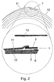
- FIG. 2 shows a diagrammatic side view of an adhesive tape according to FIG. 1, adhered to a paper roll and ready for flying splice
- FIG. 3 shows a view as in FIG. 2 but after flying splice has taken place
- FIGS. 4 a shows a diagrammatic side view of an adhesive tape of the invention with two reverse-side self-adhesive systems
- FIG. 5 a shows an adhesive tape of the invention
- FIG. 1 An exemplary embodiment of an adhesive tape of the invention is shown in FIG. 1. Illustrated is an adhesive tape 1 having a main carrier 2 comprising single-sided label paper which does not possess wet strength (basis weight 70 g/m 2 , thickness 55 ⁇ m).
- the main carrier 2 is unilaterally coated with a high-tack adhesive 3 (self-adhesive facing layer), with an application rate of 55 g/m 2 .
- the total thickness of the main carrier 2 with self-adhesive composition 3 is approximately 110 ⁇ m, the width 50 mm.
- the self-adhesive composition 3 is lined with a siliconized release paper 4 . At a distance of 17 mm from the left-hand edge said paper 4 is provided with a slit 5 , so that the left-hand part 4 a of the release paper 4 can be removed first, then the right-hand part 4 b.
- the adhesive tape 1 is provided with a strip of a self-adhesive composition 6 (reverse-side self-adhesive system), possessing shear strength, with an application rate of 40 g/m 2 ; the strip of the self-adhesive composition 6 possessing high shear strength has a width of 9 mm.
- the distance E S of the strip of the self-adhesive composition 6 possessing shear strength from the leading edge 14 of the adhesive tape 1 is 3 mm.
- the main carrier of the adhesive tape 1 is provided with a slot 7 a behind the reverse-side self-adhesive system 6 and, optionally, with a slot 7 b before the reverse-side self-adhesive system 6 .
- FIG. 2 shows how such an adhesive tape 1 is bonded beneath a paper web 11 of a new paper roll, specifically by the left-hand part, after the part 4 a of the release paper 4 has been removed from it.
- the adhesive tape with the reverse-side self-adhesive system 6 has been bonded to the paper web 12 of the paper roll lying beneath the paper web 11 .
- the right-hand part 4 b of the release paper 4 has also been removed, so that the paper roll thus equipped is ready for a flying splice, the bond of the adhesive tape 1 running at a right angle over the roll.
- the (new) paper roll thus equipped is placed next to the unwound (old) paper roll to which the new roll is to be attached.
- the new paper roll is accelerated to a speed of rotation which corresponds very closely to the speed of the expiring web. When the two speeds have been sufficiently synchronized, the splice can be performed.
- the expiring web 13 is brought into contact with the periphery of the new roll by means of a pressure shaft (not shown), and the exposed region of the self-adhesive face layer of the adhesive tape is bonded, in accordance with FIG. 3 to the expiring paper web 13 .
- the main carrier composed of splittable material splits substantially in the region in which it is equipped with the rear self-adhesive system 6 .
- a part 2 a of the main carrier 2 remains on the self-adhesive facing layer 3 , while the rear self-adhesive system 6 is nonadhesively lined with the remainder 2 b of the main carrier 2 that remains on said system 6 . Accordingly, both self-adhesive compositions ( 3 and 6 ) have been neutralized, so to speak, no longer adhere and so also no longer disrupt operation in the paper processing machines.
- FIG. 4 shows by way of example an embodiment of the adhesive tape of the invention with two reverse-side self-adhesive systems 6 .
- this embodiment is used, as well, these paper splits substantially only in each case in the regions in which the main carrier is provided with the rear self-adhesive systems 6 .
- the adhesive tape of the invention is outstandingly suitable for flying splice.
- the splitting of the main carrier 2 takes place essentially only in the region in which the main carrier 2 has been provided with the rear-side self-adhesive system 6 .
- the prior art adhesive tape possesses the following construction (cf. FIG. 5 a; shown without liners):
- a main carrier 2 * provided with a layer of a self-adhesive composition 3 * on the face and provided with a strip of a splittable system 6 * on the reverse of the main carrier.
- the splittable self-adhesive system is in turn constructed from a splittable carrier 7 *, provided with a film of a self-adhesive composition 8 * on the face of the splittable carrier, for bonding to the main carrier 2 *, and provided with a film of self-adhesive composition 9 * on the reverse of the splittable carrier, for bonding to the new paper roll.
- the adhesive tape of the invention it is possible to reduce the thickness of the bond site, which is 170 ⁇ m with prior art adhesive tapes, to 105 ⁇ m with the adhesive tape of the invention, without having to accept disadvantages in respect of the quality of the bond, particularly of the bond strengths and of the maximum web tension to be transmitted thereby, or in respect of the functionality of the splicing operation.
Landscapes
- Chemical & Material Sciences (AREA)
- Organic Chemistry (AREA)
- Adhesive Tapes (AREA)
- Adhesives Or Adhesive Processes (AREA)
- Storage Of Web-Like Or Filamentary Materials (AREA)
Abstract
Adhesive tape for the flying splice of flat web material wound up into rolls, said tape having an adhesive face and a nonadhesive reverse and also two longitudinal edges (L1, L2), and having a main carrier coated unilaterally on the face with a self-adhesive composition, only part of the nonadhesive reverse being provided with at least one self-adhesive system, wherein the main carrier is composed, at least in the region of the self-adhesive system, of splittable material.
Description
- The invention relates to an adhesive tape for the flying splice of flat web material wound up into rolls, said tape having an adhesive face, a nonadhesive reverse, and two longitudinal edges, and having a main carrier which is coated unilaterally on the face with a self-adhesive composition, a portion of the nonadhesive reverse being provided with at least one self-adhesive system, and to a process for the flying splice of flat web material wound up into reels, for which an adhesive tape of said kind is suitable.
- Flying splice in paper mills or the like is a common technique for replacing an old, almost fully unwound roll of paper by a new roll without having to stop the machines, which run at high speed. It is accomplished using double-sided self-adhesive tapes, so-called tabs, which on the one hand possess high adhesion and high tack and on the other hand, owing to their water-soluble self-adhesive compositions and paper carriers, do not interfere with re-use of the paper wastes in the paper machine. These tabs are bonded artistically in a zigzag form to the start of the web, a procedure requiring experienced personnel, with only about 4 to 13 minutes' time remaining for the entire procedure, owing to the high speed of the machines.
- Although this technology is well established, it is not without certain disadvantages. Thus, experienced personnel are required, the procedure is intrinsically hectic, and the bonds are relatively thick, since in each case two plies of web and the adhesive tab in between are the result: a result which is unwanted in the paper industry, since the high thickness may result in tearing, inter alia, at the coating blade in paper coating machines.
- There are various products on the market, known as tabs, for this butt splicing in flying splice, which in addition to a paper carrier are coated on both sides with a water-soluble self-adhesive composition. Adhesive tapes of this kind are marketed, inter alia, under the name tesafix (tesa AG).
- Additionally, the prior art includes adhesive tapes which are provided with splittable paper carriers and described, for example, in DE 196 28 317 A1 and DE 199 02 179.1-43. These adhesive tapes are also available commercially, under the names EasySplice PrintLine and FastLine.
- Although these EasySplice adhesive tapes are thinner, even in relation to the thickness of the bond site, than the conventional adhesive tapes for butt-end bonding, the type of adhesive tape described below allows a further substantial reduction in splice thickness and so distinctly reduces the probability of tearing. The thickness of standard commercial adhesive tapes for continuous bonding is 170 μm in the region of the spoilable strip in the split state. Using as example a 39 g/m 2 coating base paper (30 μm), this gives a splice thickness at the leading edge in the production direction of 200 μm. This is the important thickness, since on passage through processing machinery it comes into contact first with coating units, printing cylinders or the like, and it is here that, owing to the shape and thickness of the splice, there is a particular risk of tearing.
- Also prior art is an adhesive tape wherein the paper carrier is coated bilaterally with a water-soluble self-adhesive composition and wherein the paper carrier is composed of a readily splicing paper. This adhesive tape is described in DE 196 32 689 A1. A paper carrier is disclosed which splits across its full width. With this mode of operation there is a dramatic reduction in the ultimate tensile stress strength of the split paper and hence in the maximum possible web tension to be transmitted. In the case of centrally split papers, it is reduced by at least 50%. Where the plane of splitting is not central, the ultimate tensile stress strength may also be reduced well below 50%.
- It is an object of the invention to provide an adhesive tape for flying splice which minimizes the thickness in the region of the bond of the old web and the new web while retaining the complete ultimate tensile stress strength in order to accommodate the maximum web tension.
- This object is surprisingly achieved by the invention as set out in the main claim. The subclaims relate to advantageous developments of the invention. Further claims relate to a process for flying splice using such an adhesive tape.
- Thus, it has surprisingly and unexpectedly been found that the adhesive tapes were in the reverse of a splittable main carrier is provided only partially with a self-adhesive system are outstandingly suitable for flying splice without uncontrolled tearing of the main carrier material during the splicing operation.
- The main claim accordingly provides an adhesive tape suitable for the flying splice of flat web material wound up into rolls, having an adhesive face and partially adhesive reverse and also two
longitudinal edges adhesive tape 1 being provided with amain carrier 2 which is unilaterally coated on the face with a self-adhesive composition 3 (self-adhesive face layer), a portion of the reverse of the main carrier (covered reverse), being provided with at least one self-adhesive system 6 (reverse-side self-adhesive system), themain carrier 2 being composed, at least in the region of the self-adhesive system 6 (in the region of the covered reverse), of splittable material, so that, when a bond effected by thisadhesive tape 1 between two adherents, in particular two paper webs, is parted, themain carrier 2 of theadhesive tape 1 splits essentially only in the region of the reverse-side self-adhesive system(s) 6. - Very advantageously, the portion of the reverse equipped with one or more self-
adhesive systems 6 amounts to up to 50% of the entire area of the reverse, preferably between 6 and 48%, in particular from 18 to 24%, it also being possible for the covered portion of the reverse to be divided into two or more areas each equipped with a self-adhesive system 6. - In one preferred embodiment the rear self-
adhesive system 6 is selected such that it does not possess its own carrier but instead comprises a carrier-free self-adhesive system. Advantageously for this purpose a strip of a carrier-free self-adhesive tape is bonded to the bottom of themain carrier 2; alternatively, the self-adhesive composition can also be laminated on or applied using a nozzle. - In a further advantageous embodiment, at least one of the reverse-side self-
adhesive systems 6 also possesses a carrier (secondary carrier). In this case, for example, the reverse-side self-adhesive system may also comprise a double-sided self-adhesive tape. - The secondary carrier or carriers are advantageously selected such that their splitting resistance when the adhesive tape of the invention is employed in accordance with the invention has the effect that the secondary carrier or carriers are nonsplitting or else have a greater splitting resistance than the
main carrier 2 in the splitting region, so that themain carrier 2 splits preferentially. - The dimensions of the adhesive strip of the invention may be chosen differently depending on the field of application and intended application, and so tailored to the particular requirements. Examples of advantageous product dimensions are strips of 75 mm in width, of 50 mm in width, and of 38 mm in width, without wishing to be restricted by these figures.
- The adhesive tape of the invention may be provided with perforations or incisions allowing it to be divided into sections of defined length.
- In one preferred embodiment the reverse-side self-
adhesive system 6 or, in the case of two or more reverse-side self-adhesive systems 6, the first such system (the one lying closest to the longitudinal side 14) is indented in the region of the leading edge (longitudinal edge 14) of the adhesive tape, so that themain carrier 2 protrudes beyond the reverse-side self-adhesive system 6 on the side of the leadingedge 14 by the length ES, the indentation ES being advantageously up to 15 mm, in particular from 0.5 to 15 mm, preferably from 1 to 7 mm, very preferably from 1.5 to 3.5 mm. One specific embodiment of the adhesive tape of the invention has an indentation of ES=3mm. - In advantageous adaptation to the respective application, preference may likewise be given to using a variant of the adhesive tape of the invention wherein the (first) reverse-side self-
adhesive system 6 lies directly at the leadingside 14 of themain carrier 2—in other words, is not indented. - Moreover, for certain applications it may be of advantage if two or more self-
adhesive systems 6 are provided on the reverse of themain carrier 2, for instance such that the adhesive tape is provided with two or more self-adhesive strips. Particularly advantageous adhesive tapes are those having one or two reverse-side self-adhesive systems 6. - The reverse-side self-
adhesive systems 6 advantageously have a width of from 3 to 18 mm, in particular a width of 3 to 9 mm, especially 9 mm. - In one preferred embodiment, the
main carrier 2 may have on its reverse, at at least one point, aslit 7 a or perforation, the depth T of the slit or perforation being in particular less than the thickness of the main carrier (referred to collectively below as slot). The slot is preferably behind (slot 7 a) and where appropriate, in front of as well (slot 7 b) the reverse-side self-adhesive system(s) 6 (as viewed from the longitudinal edge 14). It may be located directly before and/or behind the self-adhesive system(s) 6, but also at some distance, advantageously up to 3 mm. In the case of two or more reverse-side self-adhesive systems 6, the slots may be provided before and/or behind each individual reverse-side self-adhesive system (in the case, for example, of large distances between the reverse-side self-adhesive systems) before and/or behind some of the reverse-side self-adhesive systems, but very advantageously before the first and/or behind the last of the reverse-side self-adhesive systems. Each slot may amount advantageously to up to 50% of the thickness of the main carrier, and supports the functioning of the adhesive tape of the invention in use such that the main carrier splits only in the desired region (region of the strip in the vicinity of the slot or between the slots) (slotting behind the rear self-adhesive system halts tear propagation). - In one advantageous embodiment of the adhesive tape of the invention the
main carrier 2 is wholly composed of splittable material. In another advantageous embodiment of the adhesive tape of the invention themain carrier 2 is composed of splittable material only in one selected region and is not (very) splittable in the other regions. This can be actualized, for example, by producing the regions with no splittability or with low splittability by stabilizing the regions which are not to be split during use, by impregnating them with appropriate chemicals, for instance, before coating with self-adhesive composition a main carrier which is splittable per se. - The
main carrier 2 is preferably composed of paper. Examples of suitable papers include, in particular, readily splittable paper systems or duplex papers. - The splittable
main carrier 2 is preferably chosen so that splitting takes place substantially symmetrically, i.e., centrally in the plane of the main carrier. Substantially symmetrically means in this context that it is ensured that, on splitting, theresidue 2 a of main carrier which remains in the splitting region is not too thin (the thickness of theresidue 2 a of main carrier should advantageously be at least 20 μm). - As
main carrier 2 it is very preferred to use a substantially symmetrically splitting paper which has a splittability (measurement method: tesa JOPM0051) of from 10 to 50 cN/cm, in particular from 20 to 40 cN/cm, very particularly from 20 to 30 cN/cm. - The measurement of the splitting resistance of the paper is carried out as follows (tesa JOPM005l):
- Test specimens: DIN A4 sheets. The specimens must be acclimatized under standardized conditions for at least 16 h.
- In the specified direction of testing (transverse unless specified otherwise), two strips of adhesive tape from both sides are placed opposite one another on the test paper and gently brushed with the finger in order to prevent air inclusions. The adhesive bond is to be produced so that on one side the ends of the adhesive tape protrude beyond the test specimen and can be folded over and bonded to one another to form a grip tab.
- A manual roller is then run over the bond rapidly, twice per side, in order to achieve an unimpaired bond strength. Using a steel rule,
strips 15 mm wide are cut out centrally from the bond, in a length of about 20 cm. The two grip tabs of the protruding adhesive tape are then pulled apart by hand until splitting of the paper test specimen is acceptable. The test specimen is then clamped into the tensile tester, hanging freely above and below by the grip tabs, and the remainder of the strip is pulled apart at a constant speed of 300 mm/min. In the case of very thin papers, care must be taken to ensure that the result is not falsified by the opposing edges of the adhesive tape contacting the edge of the test specimen and sticking. - The splitting resistance is reported in cN/cm, rounded to whole numbers, with the test direction (example: splitting resistance, transverse: 34 cN/cm).
- As already set out above, the adhesive tape of the invention has at least two self-adhesive layers, namely a
layer 3 of self-adhesive composition on the face of the main carrier 2 (self-adhesive face layer) and also a self-adhesive system 6 on the reverse of the main carrier 2 (reverse-side self-adhesive system). - The adhesive used for the self-
adhesive face layer 3 is preferably selected with a high tack (initial tack), while for the reverse-side system 6 it is advantageous to use a (self-)adhesive composition possessing shear strength. - In one very preferred embodiment of the invention the self-adhesive compositions used are acrylic pressure sensitive adhesives. With advantage, both water-soluble and water-insoluble acrylates can be used. Furthermore, it is also possible to use natural and synthetic rubber compounds and also dispersions of the compounds described above. It is pointed out that in principle all basic types of pressure sensitive adhesives which are suitable for such bonds can be used.
- On the face, adhesives of high shear strengths are of interest for application on a calender or in the case of use on a dryer. For application in the paper industry or in the case of normal newspaper printing, it is advantageous to use high-tack adhesives on the face.
- The shear strength is advantageously measured as follows (tesa JOPM002):
- The shear strength of adhesives is measured by coating them onto a standard carrier (polyester film; thickness: 25 μm). It is advantageous to select an application rate of 25 g/m 2, equal in each case.
- After drying and, where appropriate, crosslinking of the adhesive, a
strip 13 mm wide and at least 20 mm long is cut out and adhered to a defined paper (e.g., gravure paper, e.g., Neopress T 54, 54 g/m2, or coating base paper, e.g., Mediaprint, 135 g/m2). The bond area is 13 mm×20 mm. In order to ensure a constant applied pressure when bonding, the test specimen is rolled over slowly twice using a roller (weight: 2 kg). The test specimen thus produced is loaded with a weight of 1 kg parallel to the bond plane and the time for which the adhesive strip remains on the paper is recorded. - To better differentiate the individual adhesives, the test is conducted correspondingly at further test temperatures (e.g., 40° C. and 70° C.).
- In order to ensure error-free operation, the adhesive must hold a weight of 1 kg for more than 1 000 minutes on coating base paper and for more than 2 000 minutes on gravure paper at 23° C. and 55% relative humidity.
- As self-adhesive compositions of high shear strength, particularly for the self-adhesive composition 6 (reverse-side self-adhesive system), it is possible, for example, to use acrylic self-adhesive compositions of the following composition:
- from 40 to 90% by weight acrylic acid, from 60 to 10% butyl acrylate, or
- from 40 to 90% by weight acrylic acid, from 30 to 5% by weight butyl acrylate, from 30 to 5% by weight ethylhexyl acrylate
- Plasticizer addition: ethoxylated alkylamines, preferably C16 to C18, more preferably having from 15 to 25 ethoxy units.
- The blend of plasticizer of polymer amounts to from 55 to 75% by weight plasticizer and from 25 to 45% by weight polymer.
- Polymerization is performed by a free-radical mechanism in polar solvents using ethanol as regulator. Partial crosslinking takes place when the pressure sensitive adhesive films of the polyvalent cations are dried by addition of aluminum chelate or titanium chelate (from 0.3 to 1.2% by weight, based on the total amount).
- As self-adhesive compositions of high tack, particularly for the self-
adhesive composition 3, it is possible, for example, to use acrylic adhesives of the following composition: - from 30 to 70% by weight acrylic acid, from 15 to 35% by weight butyl acrylate, from 15 to 35% by weight ethylhexyl acrylate
- Plasticizer addition: ethoxylated alkylamines, preferably C16 to C18, more preferably having from 15 to 25 ethoxy units.
- The blend of plasticizer of polymer amounts to from 55 to 75% by weight plasticizer and from 25 to 45% by weight polymer.
- Polymerization is performed by a free-radical mechanism in polar solvents using ethanol as regulator. Partial crosslinking takes place when the pressure sensitive adhesive films of the polyvalent cations are dried by addition of aluminum chelate or titanium chelate (from 0.1 to 0.5% by weight, based on the total amount).
- As further examples of self-adhesive compositions which can be used with advantage, mention may be made of repulpable pressure sensitive adhesives based on a graft polymer in which from 3 to 20% by weight of vinyl compounds containing sulfonic-acid salt groups have been grafted onto a copolymer of (meth)acrylates and (meth)acrylic acid, and which has been formulated for pressure sensitive adhesion using water-soluble plasticizers. Incorporated by reference in this context is the entire disclosure content of DE 43 40 297 A1 and of U.S. Pat. No. 5,489,642.
- As advantageous possibilities for use, mention may further be made of a water-soluble pressure sensitive self-adhesive composition composed of a mixture containing, based on 100 parts by weight of solids,
- a) from 30 to 80 parts by weight of a copolymer of 70 to 88% by weight butyl acrylate and 12 to 30% by weight of vinylcarboxylic acid, from 3 to 12% by weight of whose butyl acrylate fraction, based on the total weight of the monomers, may have been replaced by 2-ethylhexyl acrylate and/or from 5 to 25% by weight of whose butyl acrylate content, based on the total weight of the monomers, may have been replaced by a mixture of vinyl acetate and a dialkyl fumarate, and
- b) from 20 to 70 parts by weight of an ethoxylated (alkyl)phenol, an ethoxylated alkyl monoamine or alkyl diamine or an ethoxylated alkylammonium compound as plasticizer, the acid content of the copolymer having been neutralized almost completely with potassium hydroxide (solution), preferably with the use of an excess of this base.
- Accordingly, the entire technical disclosure content of DE 31 05 894 A1 may be incorporated here.
- In a further preferred embodiment, the self-
adhesive face layer 3 is provided with aliner 4 which is provided where appropriate with a perforation or aslit 5 in the longitudinal direction. As liner material it is possible, for example, to use siliconized release paper. Theslit 5 may preferably be provided at a distance A of from 10 to 40 mm from thelongitudinal edge 15 of the adhesive tape which is opposite to the leadinglongitudinal edge 14 in the vicinity of which the self-adhesive system 6 is arranged. In order to ensure the full tensile strength of thepaper backing 2 and of the web tensions to be transmitted maximally therewith, the distance M between theslit 5 in the release paper and theslot 7 a in the main carrier, is advantageously at least 5 mm. - In one advantageous embodiment, the adhesive tape is equipped with at least one means, detectable mechanically (without contact) by means of a detector, detection being achieved preferably by means of metal, transponder systems, or optical devices.
- In one preferred variant the main carrier or regions thereof is or are composed of material to which at least one detectable additive has been added, and/or the main carrier comprises at least one layer of a detectable material.
- In one embodiment of the inventive adhesive tape, for example, metal powder or granules are admixed to the actual main carrier material, or the substructure of the main carrier is provided with one or more metal layers. In another variant of the inventive adhesive tape the integrated signal function is realized by providing the main carrier on the top and/or bottom with an aluminum layer, advantageously over the full area. Instead of aluminum, any other materials detectable in accordance with the requirements may be used as layer, particularly metals, examples being copper, silver, and gold.
- Layers of this kind are located advantageously on the face of the adhesive tape or of the main carrier.
- In a following embodiment of the invention, the detection is brought about by means of transponder systems, in particular thin-film transponders, which are integrated into the adhesive tape. Versions with active and passive transponders are realizable here.
- In another embodiment of the inventive adhesive tape the adhesive tape is provided with optically registerable means. These may, for example, be bar codes which can be read by a laser. When bar codes are used it is possible, in addition to the actual detection effect, to transmit information as well, on the nature or web thickness of the new roll, for example. Thus when using rolls of different kind or quality it is possible to adjust the processing unit automatically to the new processing conditions without the need for a further external control.
- The functioning of optical reflectors or diffraction gratings mounted in or on the main carrier of the adhesive tape is similar. They may likewise be detected optically and initiate the splicing operation.
- A further example of optically detectable devices are defined colorations of the main carrier which can likewise be registered by means of suitable detecting systems.
- The invention further provides a process for the flying splice of flat web material wound up into rolls, in which the
topmost paper web 11 of a new roll is fixed with anadhesive tape 1 which has amain carrier 2 coated unilaterally on the face with a self-adhesive composition 3, and in which a portion of the reverse is equipped with at least one self-adhesive system 6, to theunderlying web 12 and a portion of the self-adhesive face layer 3 which is needed for the splicing process lies exposed, whereupon the new roll thus equipped is placed adjacent to an almost fully unwound old roll requiring replacement and is accelerated to substantially the same speed of rotation as said roll, then is pressed against theold web 13, the exposed region of the self-adhesive face layer 3 of theadhesive tape 1 adhering to theold web 13 with substantially identical web speeds, while at the same time themain carrier 2, made of spliceable material, splits substantially in the region in which it is equipped with the rear self-adhesive system 6 in such a way that after the splitting operation there are no adhesive regions exposed. - In a development of the inventive process, the
adhesive tape 1 is bonded at right angles to the running paper web. In one advantageous variant of the inventive process, the adhesive tape may also be bonded at an acute angle of up to 30° with respect to the running paper web, in particular an angle of up to 10°. - In the splicing process, an
adhesive tape 1 is bonded in a straight line beneath thetopmost web 11 to a new paper roll. Bonding takes place such that a part of theadhesive tape 1 remains free for bonding with the expiringweb 13. - The
adhesive tape 1 is preferably bonded in a straight line beneath thetopmost paper web 11 of the new roll so that a part of theadhesive tape 1 remains free while the reverse-side self-adhesive system 6 of theadhesive tape 1 bonds to theunderlying web 12 and thus secures thetopmost web 11. If desired, first of all only apart 4 a of theliner 4 present where appropriate on the self-adhesive face layer 3 has been removed, so that the part of the self-adhesive layer 3 that is required for the splicing process is still lined with theliner 4 b and the roll in this state does not have a free adhering surface. At this point, for final preparation for the splicing process, any remainingliner 4 b still present is removed, after which the new roll thus equipped is placed adjacent to an old roll which has almost totally unwound and requires replacement, and is accelerated to the same speed of rotation as the old roll, then is pressed against theold web 13, the exposed region of the self-adhesive face layer 3 of theadhesive tape 1 bonding to theold web 13, with the speeds of the web being substantially the same, while at the same time themain carrier 2 splits substantially in the region in which it is equipped with the rear self-adhesive system 6 and nonadhesively lines the rear self-adhesive system 6 with the remnant 2 a of themain carrier 2 which remains onsaid system 6. - After contact of the
adhesive tape 1 with the expiringweb 13, therefore, themain carrier 2 of the adhesive tape splits in the region provided with the reverse-side self-adhesive system 6, so that the topmost paper ply 11 of the new bale is released and there are no longer any sticky residues. - The aim below is to describe the invention in more detail with reference to an exemplary embodiment, without, however, wishing to restrict it unnecessarily by so doing.
- In the drawings
- FIG. 1 shows a diagrammatic side view of an adhesive tape of the invention
- FIG. 2 shows a diagrammatic side view of an adhesive tape according to FIG. 1, adhered to a paper roll and ready for flying splice
- FIG. 3 shows a view as in FIG. 2 but after flying splice has taken place FIGS. 4 a) shows a diagrammatic side view of an adhesive tape of the invention with two reverse-side self-adhesive systems
- b) a view of the adhesive tape from FIG. 4 a) in accordance with FIG. 2
- FIG. 5 a) shows an adhesive tape of the invention
- b) and an adhesive tape according to the prior art in a comparison of the layer thicknesses
- An exemplary embodiment of an adhesive tape of the invention is shown in FIG. 1. Illustrated is an
adhesive tape 1 having amain carrier 2 comprising single-sided label paper which does not possess wet strength (basis weight 70 g/m2, thickness 55 μm). Themain carrier 2 is unilaterally coated with a high-tack adhesive 3 (self-adhesive facing layer), with an application rate of 55 g/m2. The total thickness of themain carrier 2 with self-adhesive composition 3 is approximately 110 μm, the width 50 mm. The self-adhesive composition 3 is lined with asiliconized release paper 4. At a distance of 17 mm from the left-hand edge saidpaper 4 is provided with aslit 5, so that the left-hand part 4 a of therelease paper 4 can be removed first, then the right-hand part 4 b. - At the right-hand end the
adhesive tape 1 is provided with a strip of a self-adhesive composition 6 (reverse-side self-adhesive system), possessing shear strength, with an application rate of 40 g/m2; the strip of the self-adhesive composition 6 possessing high shear strength has a width of 9 mm. The distance ES of the strip of the self-adhesive composition 6 possessing shear strength from the leadingedge 14 of theadhesive tape 1 is 3 mm. - The main carrier of the
adhesive tape 1 is provided with aslot 7 a behind the reverse-side self-adhesive system 6 and, optionally, with aslot 7 b before the reverse-side self-adhesive system 6. - FIG. 2 shows how such an
adhesive tape 1 is bonded beneath apaper web 11 of a new paper roll, specifically by the left-hand part, after thepart 4 a of therelease paper 4 has been removed from it. Beforehand, the adhesive tape with the reverse-side self-adhesive system 6 has been bonded to thepaper web 12 of the paper roll lying beneath thepaper web 11. The right-hand part 4 b of therelease paper 4 has also been removed, so that the paper roll thus equipped is ready for a flying splice, the bond of theadhesive tape 1 running at a right angle over the roll. - Part of the self-
adhesive face layer 3 is now exposed and represents the area of contact with expiring webs for the flying splice. The contact area has a width of 33 mm and extends across the entire width of the paper roll. - The (new) paper roll thus equipped is placed next to the unwound (old) paper roll to which the new roll is to be attached. The new paper roll is accelerated to a speed of rotation which corresponds very closely to the speed of the expiring web. When the two speeds have been sufficiently synchronized, the splice can be performed.
- The expiring
web 13 is brought into contact with the periphery of the new roll by means of a pressure shaft (not shown), and the exposed region of the self-adhesive face layer of the adhesive tape is bonded, in accordance with FIG. 3 to the expiringpaper web 13. A moment after adhesive contact, the main carrier composed of splittable material splits substantially in the region in which it is equipped with the rear self-adhesive system 6. Apart 2 a of themain carrier 2 remains on the self-adhesive facing layer 3, while the rear self-adhesive system 6 is nonadhesively lined with theremainder 2 b of themain carrier 2 that remains onsaid system 6. Accordingly, both self-adhesive compositions (3 and 6) have been neutralized, so to speak, no longer adhere and so also no longer disrupt operation in the paper processing machines. - FIG. 4 shows by way of example an embodiment of the adhesive tape of the invention with two reverse-side self-
adhesive systems 6. When this embodiment is used, as well, these paper splits substantially only in each case in the regions in which the main carrier is provided with the rear self-adhesive systems 6. - Unexpectedly, the adhesive tape of the invention is outstandingly suitable for flying splice. Thus, given a suitable design of the
adhesive tape 1, the splitting of themain carrier 2 takes place essentially only in the region in which themain carrier 2 has been provided with the rear-side self-adhesive system 6. - Very advantageously, with the
adhesive tape 1 of the invention it is possible to reduce sharply the thickness of the join at the transition from the old roll to the new one. This gives rise to considerable technical advantages for the untroubled progress of the paper processing operation. The advantage will be depicted here by way of example in comparison with a prior art adhesive tape for flying splice (cf., for example, DE 196 28 317 A1, DE 199 02 179 A1): - The prior art adhesive tape possesses the following construction (cf. FIG. 5 a; shown without liners):
- A
main carrier 2*, provided with a layer of a self-adhesive composition 3* on the face and provided with a strip of asplittable system 6* on the reverse of the main carrier. The splittable self-adhesive system is in turn constructed from asplittable carrier 7*, provided with a film of a self-adhesive composition 8* on the face of the splittable carrier, for bonding to themain carrier 2*, and provided with a film of self-adhesive composition 9* on the reverse of the splittable carrier, for bonding to the new paper roll.The layer thicknesses are as follows: self- adhesive layer 3* (application rate 55 g/m2)50 μm main carrier 2*65 μm self- adhesive layer 8* (application rate 30 g/m2)27.5 μm splittable carrier 7*55 μm self- adhesive layer 9* (application rate 40 g/m2)37.5 μm = 235 μm after the splicing operation, assuming symmetrical splitting of the carrier: minus thickness of the self- adhesive layer 9*minus half the thickness of the splittable =170 μm carrier 7* - The adhesive tape of the invention, on the other hand, has the following dimensions (FIG. 5 b):
self-adhesive composition 3 (application rate 55 g/m2) 50 μm main carrier 255 μm self-adhesive composition 6 (application rate 40 g/m2) 37.5 μm = 142.5 μm after the splicing operation, assuming symmetrical splitting of the main carrier: minus thickness of the self- adhesive layer 6*= 105 μm - With the adhesive tape of the invention it is possible to reduce the thickness of the bond site, which is 170 μm with prior art adhesive tapes, to 105 μm with the adhesive tape of the invention, without having to accept disadvantages in respect of the quality of the bond, particularly of the bond strengths and of the maximum web tension to be transmitted thereby, or in respect of the functionality of the splicing operation.
Claims (19)
1. An adhesive tape suitable for flying splicing of flat web material wound up into rolls, said adhesive tape having an adhesive face, a partially adhesive opposite face and two longitudinal edges, said adhesive tape comprising a main carrier, which is unilaterally coated on a face thereof with a self-adhesive composition, and provided in a region on a reverse face thereof with at least one self-adhesive system, the main carrier being composed, at least in the region where the at least one self-adhesive system is provided, of a splittable material, so that when a bond effected by the adhesive tape between two adherents is parted, the main carrier splits essentially only in the region where the at least one self-adhesive system is provided.
2. The adhesive tape according to claim 1 , wherein the region where the at least one self-adhesive system is provided amounts to up to 50% of a total area of the reverse face.
3. The adhesive tape according to claim 2 , wherein the region where the at least one self-adhesive system is provided amounts to between 6 and 48% of a total area of the reverse face.
4. The adhesive tape according to claim 3 , wherein the region where the at least one self-adhesive system is provided amounts to between 18 and 25% of a total area of the reverse face.
5. The adhesive tape according to claim 1 , wherein one self-adhesive system is arranged at a distance of from 0.5 to 15 mm from one longitudinal edge of the adhesive tape.
6. The adhesive tape according to claim 5 , wherein one self-adhesive system is arranged at a distance of from 1 to 7 mm from one longitudinal edge of the adhesive tape.
7. The adhesive tape according to claim 6 , wherein one self-adhesive system is arranged at a distance of from 1.5 to 3.5 mm from one longitudinal edge of the adhesive tape.
8. The adhesive tape according to claim 1 , wherein the main carrier has on the reverse face one or more perforations or slits.
9. The adhesive tape according to claim 8 , wherein each of said perforations or slits has a depth which is smaller than a thickness of the main carrier.
10. The adhesive tape according to claim 8 , wherein the depth of said perforations or slits is not more than 50% of the thickness of the main carrier.
11. The adhesive tape according to claim 1 , wherein the main carrier is composed completely of splittable material.
12. The adhesive tape according to claim 1 , wherein the main carrier is not composed completely of splittable material.
13. The adhesive tape according to claim 1 , wherein the main carrier comprises a substantially symmetrically splitting paper.
14. The adhesive tape according to claim 13 , wherein the substantially symmetrically splitting paper has a splittability of from 10 to 50 cN/cm.
15. The adhesive tape according to claim 14 , wherein the substantially symmetrically splitting paper has a splittability of from 20 to 40 cN/cm.
16. The adhesive tape according to claim 15 , wherein the substantially symmetrically splitting paper has a splittability of from 20 to 30 cN/cm.
17. The adhesive tape according to claim 1 , wherein the self-adhesive composition is lined with a release material.
18. The adhesive tape according to claim 1 , wherein the release material is provided with a slit or perforation.
19. A method for effecting a flying splice of flat web material wound up into rolls, said method comprising:
a) providing an adhesive tape according to claim 1;
b) adhering a portion of said adhesive face to an underside of a topmost web of a new roll of material;
c) adhering said at least one self-adhesive system to a topside of an underlying web of said new roll of material;
d) accelerating said new roll of material to substantially the same speed as an unwinding roll of material;
e) pressing the new roll against the unwinding roll of material in a manner so as to cause an unadhered portion of said adhesive face to adhere to said unwinding roll of material, thereby effecting a splice between said new roll and said unwinding roll of material, and also causing the main carrier to split in the region where the at least one self-adhesive system is provided in such a way that after splitting, there are no exposed adhesive regions.
Applications Claiming Priority (2)
| Application Number | Priority Date | Filing Date | Title |
|---|---|---|---|
| DE10210192.2 | 2002-03-07 | ||
| DE10210192A DE10210192A1 (en) | 2002-03-07 | 2002-03-07 | Adhesive tape for flying roll changes |
Publications (2)
| Publication Number | Publication Date |
|---|---|
| US20030190445A1 true US20030190445A1 (en) | 2003-10-09 |
| US7152825B2 US7152825B2 (en) | 2006-12-26 |
Family
ID=27740697
Family Applications (1)
| Application Number | Title | Priority Date | Filing Date |
|---|---|---|---|
| US10/376,036 Expired - Fee Related US7152825B2 (en) | 2002-03-07 | 2003-02-27 | Adhesive tape for flying splice |
Country Status (6)
| Country | Link |
|---|---|
| US (1) | US7152825B2 (en) |
| EP (1) | EP1342684A3 (en) |
| JP (1) | JP2003261846A (en) |
| KR (1) | KR20040030191A (en) |
| CA (1) | CA2417293A1 (en) |
| DE (1) | DE10210192A1 (en) |
Cited By (11)
| Publication number | Priority date | Publication date | Assignee | Title |
|---|---|---|---|---|
| US20040192856A1 (en) * | 2003-03-26 | 2004-09-30 | Tesa Aktiengesellschaft | Adhesive |
| US20040256515A1 (en) * | 2001-09-03 | 2004-12-23 | Markus Eikmeier | Adhesive strip for continuous adhesion on a calender |
| US20050000627A1 (en) * | 2001-05-17 | 2005-01-06 | Uwe Weinberg | Closing banding |
| US20060002690A1 (en) * | 2004-07-01 | 2006-01-05 | Eastman Kodak Company | Intelligent media splice |
| EP1640301A1 (en) | 2004-09-23 | 2006-03-29 | Tesa AG | Adhesive tape for flying splicing with a cleavable system while changing the web roll. |
| US20080081186A1 (en) * | 2006-02-22 | 2008-04-03 | Tesa Aktiengesellschaft | Adhesive tape and its use |
| US20080152817A1 (en) * | 2006-12-22 | 2008-06-26 | Kelly Michael Dewayne | Curable aqueous compositions |
| US20140057769A1 (en) * | 2011-04-15 | 2014-02-27 | Robert Bosch Gmbh | Method and device for connecting two film webs |
| WO2019190525A1 (en) * | 2018-03-29 | 2019-10-03 | Nitto Belgium Nv | Adhesive tape for automatic reel change |
| US10494548B2 (en) | 2015-07-27 | 2019-12-03 | Tesa Se | Adhesive tape for flying splice |
| US10858209B2 (en) | 2015-11-12 | 2020-12-08 | Tesa Se | Adhesive tape and its use |
Families Citing this family (13)
| Publication number | Priority date | Publication date | Assignee | Title |
|---|---|---|---|---|
| DE102004040814A1 (en) * | 2004-08-24 | 2006-03-02 | Tesa Ag | Adhesive tape for making a splice connection |
| DE102007048280A1 (en) * | 2007-10-08 | 2009-04-09 | Tesa Ag | Adhesive tape for the flying reel change |
| DE102007053432A1 (en) | 2007-11-07 | 2009-05-14 | Tesa Ag | Pressure-sensitive adhesive tapes for changing reels of flat web materials |
| DE102008021247A1 (en) | 2008-04-28 | 2009-10-29 | Tesa Se | Adhesive tape for the roll change of flat web materials |
| DE102008023020B4 (en) | 2008-05-09 | 2015-05-07 | Tesa Se | Adhesive tape for carrying out a flying roll change |
| DE102008060181A1 (en) * | 2008-06-03 | 2009-12-10 | Tesa Se | Adhesive tape and its use |
| DE102008059384A1 (en) * | 2008-06-03 | 2009-12-17 | Tesa Se | Adhesive tape and its use |
| DE102008047966A1 (en) | 2008-09-18 | 2010-03-25 | Tesa Se | Repulpable adhesives |
| US20100086778A1 (en) * | 2008-10-08 | 2010-04-08 | Shurtape Technologies, Inc. | Multilayer adhesive tape |
| PH12013500452A1 (en) | 2010-09-16 | 2022-05-02 | Electroreel Components Llc | Component carrier reel splicing tape |
| US9315351B2 (en) | 2010-09-16 | 2016-04-19 | Electroreel Components, Llc | Component carrier reel splicing tape |
| TW201315790A (en) | 2011-10-05 | 2013-04-16 | Bk Chemical Co Ltd | Doubled-sided self-splittable adhesive tape for dynamic splicing and its method of use |
| CN114212582B (en) * | 2021-12-27 | 2024-05-24 | 安徽格林开思茂光电科技股份有限公司 | Adhesive tape winding and unwinding device |
Citations (8)
| Publication number | Priority date | Publication date | Assignee | Title |
|---|---|---|---|---|
| US5212002A (en) * | 1990-04-03 | 1993-05-18 | J. M. Voith Gmbh | Splice and process for making a splice on the leader of a paper roll |
| US5489642A (en) * | 1993-11-26 | 1996-02-06 | Beiersdorf Aktiengesellschaft | Repulpable contact adhesive |
| US5692699A (en) * | 1993-04-26 | 1997-12-02 | Minnesota Mining And Manufacturing Company | Splicing tape, splicing method and splice using the splicing tape |
| US5901919A (en) * | 1996-07-13 | 1999-05-11 | Beiersdorf Ag | Adhesive tape and method of using it |
| US5916651A (en) * | 1996-08-14 | 1999-06-29 | Beiersdorf Ag | Adhesive tape and method of using it |
| US20010003617A1 (en) * | 1999-12-02 | 2001-06-14 | Reinhard Storbeck | Adhesive tape |
| US20020045019A1 (en) * | 2000-06-14 | 2002-04-18 | Thomas Gassner | Fixing label |
| US6595461B1 (en) * | 1999-01-21 | 2003-07-22 | Tesa Ag | Adhesive tape |
Family Cites Families (5)
| Publication number | Priority date | Publication date | Assignee | Title |
|---|---|---|---|---|
| SE466346B (en) * | 1989-12-01 | 1992-02-03 | Jan Olof Norrman | SETTING TO SPRAY A CURRENT MATERIALS LABEL WITH AN ADMINISTRATIVE ELEMENT |
| JP3046445B2 (en) | 1992-02-10 | 2000-05-29 | 日東電工株式会社 | Water soluble double sided tape for splicing |
| DE4210329A1 (en) * | 1992-03-30 | 1993-10-07 | Koenig & Bauer Ag | Arrangement for connecting successive paper webs wound into rolls |
| DE19544010C2 (en) | 1995-11-27 | 2001-10-04 | Peter Prinz | Label for flying reel changes |
| DE19830673A1 (en) * | 1998-07-09 | 2000-01-13 | Beiersdorf Ag | Adhesive tape and its use |
-
2002
- 2002-03-07 DE DE10210192A patent/DE10210192A1/en not_active Withdrawn
-
2003
- 2003-01-24 CA CA002417293A patent/CA2417293A1/en not_active Abandoned
- 2003-02-08 EP EP03002851A patent/EP1342684A3/en not_active Withdrawn
- 2003-02-27 JP JP2003051335A patent/JP2003261846A/en active Pending
- 2003-02-27 US US10/376,036 patent/US7152825B2/en not_active Expired - Fee Related
- 2003-03-06 KR KR1020030014008A patent/KR20040030191A/en not_active Withdrawn
Patent Citations (8)
| Publication number | Priority date | Publication date | Assignee | Title |
|---|---|---|---|---|
| US5212002A (en) * | 1990-04-03 | 1993-05-18 | J. M. Voith Gmbh | Splice and process for making a splice on the leader of a paper roll |
| US5692699A (en) * | 1993-04-26 | 1997-12-02 | Minnesota Mining And Manufacturing Company | Splicing tape, splicing method and splice using the splicing tape |
| US5489642A (en) * | 1993-11-26 | 1996-02-06 | Beiersdorf Aktiengesellschaft | Repulpable contact adhesive |
| US5901919A (en) * | 1996-07-13 | 1999-05-11 | Beiersdorf Ag | Adhesive tape and method of using it |
| US5916651A (en) * | 1996-08-14 | 1999-06-29 | Beiersdorf Ag | Adhesive tape and method of using it |
| US6595461B1 (en) * | 1999-01-21 | 2003-07-22 | Tesa Ag | Adhesive tape |
| US20010003617A1 (en) * | 1999-12-02 | 2001-06-14 | Reinhard Storbeck | Adhesive tape |
| US20020045019A1 (en) * | 2000-06-14 | 2002-04-18 | Thomas Gassner | Fixing label |
Cited By (17)
| Publication number | Priority date | Publication date | Assignee | Title |
|---|---|---|---|---|
| US7255764B2 (en) * | 2001-05-17 | 2007-08-14 | Tesa Ag | Closing banding |
| US20050000627A1 (en) * | 2001-05-17 | 2005-01-06 | Uwe Weinberg | Closing banding |
| US20040256515A1 (en) * | 2001-09-03 | 2004-12-23 | Markus Eikmeier | Adhesive strip for continuous adhesion on a calender |
| US20040192856A1 (en) * | 2003-03-26 | 2004-09-30 | Tesa Aktiengesellschaft | Adhesive |
| US20060002690A1 (en) * | 2004-07-01 | 2006-01-05 | Eastman Kodak Company | Intelligent media splice |
| CN1752168B (en) * | 2004-09-23 | 2012-04-11 | 德莎欧洲公司 | Adhesive tape with cleavable system for producing connections during on-the-fly reel changes |
| EP1640301A1 (en) | 2004-09-23 | 2006-03-29 | Tesa AG | Adhesive tape for flying splicing with a cleavable system while changing the web roll. |
| US20080081186A1 (en) * | 2006-02-22 | 2008-04-03 | Tesa Aktiengesellschaft | Adhesive tape and its use |
| US8268442B2 (en) * | 2006-02-22 | 2012-09-18 | Tesa Se | Adhesive tape and its use |
| EP1989136B2 (en) † | 2006-02-22 | 2015-02-25 | Tesa Se | Adhesive tape and its use |
| US20080152817A1 (en) * | 2006-12-22 | 2008-06-26 | Kelly Michael Dewayne | Curable aqueous compositions |
| US8299153B2 (en) | 2006-12-22 | 2012-10-30 | Rohm And Haas Company | Curable aqueous compositions |
| AU2007246196B2 (en) * | 2006-12-22 | 2012-11-29 | Rohm And Haas Company | Curable aqueous compositions |
| US20140057769A1 (en) * | 2011-04-15 | 2014-02-27 | Robert Bosch Gmbh | Method and device for connecting two film webs |
| US10494548B2 (en) | 2015-07-27 | 2019-12-03 | Tesa Se | Adhesive tape for flying splice |
| US10858209B2 (en) | 2015-11-12 | 2020-12-08 | Tesa Se | Adhesive tape and its use |
| WO2019190525A1 (en) * | 2018-03-29 | 2019-10-03 | Nitto Belgium Nv | Adhesive tape for automatic reel change |
Also Published As
| Publication number | Publication date |
|---|---|
| US7152825B2 (en) | 2006-12-26 |
| KR20040030191A (en) | 2004-04-09 |
| EP1342684A2 (en) | 2003-09-10 |
| EP1342684A3 (en) | 2004-11-17 |
| JP2003261846A (en) | 2003-09-19 |
| CA2417293A1 (en) | 2003-09-07 |
| DE10210192A1 (en) | 2003-10-09 |
Similar Documents
| Publication | Publication Date | Title |
|---|---|---|
| US7152825B2 (en) | Adhesive tape for flying splice | |
| US20070128432A1 (en) | Adhesive tape for automatic replacement of rolls | |
| US20020056784A1 (en) | Tape for flying splice, method of use, and method of manufacture | |
| JP4666911B2 (en) | Adhesive tape that can be detected by machine | |
| US7108220B2 (en) | Adhesive tape | |
| US9034451B2 (en) | Splicing adhesive tape comprising splittable connector elements | |
| KR101617789B1 (en) | Adhesive tape for roll change of flat-web materials | |
| US7240874B2 (en) | Machine-detectable adhesive tape | |
| US8545653B2 (en) | Adhesive tape for producing a joint during a static reel change | |
| KR100929299B1 (en) | Bonding Tape with Self-Adhesive Composition and Bonding Method Using Adhesive Tape | |
| JP6122465B2 (en) | Use of splice tape with laminate strips arranged in parallel to each other, splice tape, splicing method using the splice tape, and winding roll comprising the splice tape | |
| US20020045019A1 (en) | Fixing label | |
| US20030134111A1 (en) | Adhesive tape for reel changeover and use thereof |
Legal Events
| Date | Code | Title | Description |
|---|---|---|---|
| AS | Assignment |
Owner name: TESA AKTIENGESELLSCHAFT, GERMANY Free format text: ASSIGNMENT OF ASSIGNORS INTEREST;ASSIGNOR:NOOTBAAR, JENS;REEL/FRAME:014096/0222 Effective date: 20030415 |
|
| REMI | Maintenance fee reminder mailed | ||
| AS | Assignment |
Owner name: TESA SE, GERMANY Free format text: CHANGE OF NAME;ASSIGNOR:TESA AG;REEL/FRAME:025095/0915 Effective date: 20090331 |
|
| LAPS | Lapse for failure to pay maintenance fees | ||
| STCH | Information on status: patent discontinuation |
Free format text: PATENT EXPIRED DUE TO NONPAYMENT OF MAINTENANCE FEES UNDER 37 CFR 1.362 |