US20030190198A1 - Bulk material pump feeder - Google Patents
Bulk material pump feeder Download PDFInfo
- Publication number
- US20030190198A1 US20030190198A1 US10/119,359 US11935902A US2003190198A1 US 20030190198 A1 US20030190198 A1 US 20030190198A1 US 11935902 A US11935902 A US 11935902A US 2003190198 A1 US2003190198 A1 US 2003190198A1
- Authority
- US
- United States
- Prior art keywords
- housing
- drive
- wall
- drive discs
- outlet
- Prior art date
- Legal status (The legal status is an assumption and is not a legal conclusion. Google has not performed a legal analysis and makes no representation as to the accuracy of the status listed.)
- Granted
Links
- 239000013590 bulk material Substances 0.000 title description 2
- 239000000463 material Substances 0.000 claims abstract description 104
- 238000007790 scraping Methods 0.000 claims description 16
- 238000011144 upstream manufacturing Methods 0.000 claims description 2
- 230000000694 effects Effects 0.000 description 3
- 238000005007 materials handling Methods 0.000 description 3
- 239000003245 coal Substances 0.000 description 2
- 230000002411 adverse Effects 0.000 description 1
- 238000010276 construction Methods 0.000 description 1
- 230000001419 dependent effect Effects 0.000 description 1
- 238000012986 modification Methods 0.000 description 1
- 230000004048 modification Effects 0.000 description 1
Images


Classifications
-
- B—PERFORMING OPERATIONS; TRANSPORTING
- B65—CONVEYING; PACKING; STORING; HANDLING THIN OR FILAMENTARY MATERIAL
- B65G—TRANSPORT OR STORAGE DEVICES, e.g. CONVEYORS FOR LOADING OR TIPPING, SHOP CONVEYOR SYSTEMS OR PNEUMATIC TUBE CONVEYORS
- B65G53/00—Conveying materials in bulk through troughs, pipes or tubes by floating the materials or by flow of gas, liquid or foam
- B65G53/34—Details
- B65G53/40—Feeding or discharging devices
- B65G53/46—Gates or sluices, e.g. rotary wheels
-
- F—MECHANICAL ENGINEERING; LIGHTING; HEATING; WEAPONS; BLASTING
- F04—POSITIVE - DISPLACEMENT MACHINES FOR LIQUIDS; PUMPS FOR LIQUIDS OR ELASTIC FLUIDS
- F04D—NON-POSITIVE-DISPLACEMENT PUMPS
- F04D23/00—Other rotary non-positive-displacement pumps
-
- B—PERFORMING OPERATIONS; TRANSPORTING
- B65—CONVEYING; PACKING; STORING; HANDLING THIN OR FILAMENTARY MATERIAL
- B65G—TRANSPORT OR STORAGE DEVICES, e.g. CONVEYORS FOR LOADING OR TIPPING, SHOP CONVEYOR SYSTEMS OR PNEUMATIC TUBE CONVEYORS
- B65G31/00—Mechanical throwing machines for articles or solid materials
- B65G31/04—Mechanical throwing machines for articles or solid materials comprising discs, drums, or like rotary impellers
-
- B—PERFORMING OPERATIONS; TRANSPORTING
- B65—CONVEYING; PACKING; STORING; HANDLING THIN OR FILAMENTARY MATERIAL
- B65G—TRANSPORT OR STORAGE DEVICES, e.g. CONVEYORS FOR LOADING OR TIPPING, SHOP CONVEYOR SYSTEMS OR PNEUMATIC TUBE CONVEYORS
- B65G53/00—Conveying materials in bulk through troughs, pipes or tubes by floating the materials or by flow of gas, liquid or foam
- B65G53/34—Details
- B65G53/40—Feeding or discharging devices
- B65G53/42—Nozzles
-
- F—MECHANICAL ENGINEERING; LIGHTING; HEATING; WEAPONS; BLASTING
- F04—POSITIVE - DISPLACEMENT MACHINES FOR LIQUIDS; PUMPS FOR LIQUIDS OR ELASTIC FLUIDS
- F04D—NON-POSITIVE-DISPLACEMENT PUMPS
- F04D17/00—Radial-flow pumps, e.g. centrifugal pumps; Helico-centrifugal pumps
- F04D17/08—Centrifugal pumps
- F04D17/16—Centrifugal pumps for displacing without appreciable compression
-
- F—MECHANICAL ENGINEERING; LIGHTING; HEATING; WEAPONS; BLASTING
- F04—POSITIVE - DISPLACEMENT MACHINES FOR LIQUIDS; PUMPS FOR LIQUIDS OR ELASTIC FLUIDS
- F04D—NON-POSITIVE-DISPLACEMENT PUMPS
- F04D29/00—Details, component parts, or accessories
- F04D29/18—Rotors
- F04D29/22—Rotors specially for centrifugal pumps
- F04D29/2261—Rotors specially for centrifugal pumps with special measures
- F04D29/2266—Rotors specially for centrifugal pumps with special measures for sealing or thrust balance
-
- F—MECHANICAL ENGINEERING; LIGHTING; HEATING; WEAPONS; BLASTING
- F04—POSITIVE - DISPLACEMENT MACHINES FOR LIQUIDS; PUMPS FOR LIQUIDS OR ELASTIC FLUIDS
- F04D—NON-POSITIVE-DISPLACEMENT PUMPS
- F04D29/00—Details, component parts, or accessories
- F04D29/40—Casings; Connections of working fluid
- F04D29/42—Casings; Connections of working fluid for radial or helico-centrifugal pumps
- F04D29/426—Casings; Connections of working fluid for radial or helico-centrifugal pumps especially adapted for liquid pumps
-
- F—MECHANICAL ENGINEERING; LIGHTING; HEATING; WEAPONS; BLASTING
- F04—POSITIVE - DISPLACEMENT MACHINES FOR LIQUIDS; PUMPS FOR LIQUIDS OR ELASTIC FLUIDS
- F04D—NON-POSITIVE-DISPLACEMENT PUMPS
- F04D7/00—Pumps adapted for handling specific fluids, e.g. by selection of specific materials for pumps or pump parts
- F04D7/02—Pumps adapted for handling specific fluids, e.g. by selection of specific materials for pumps or pump parts of centrifugal type
- F04D7/04—Pumps adapted for handling specific fluids, e.g. by selection of specific materials for pumps or pump parts of centrifugal type the fluids being viscous or non-homogenous
- F04D7/045—Pumps adapted for handling specific fluids, e.g. by selection of specific materials for pumps or pump parts of centrifugal type the fluids being viscous or non-homogenous with means for comminuting, mixing stirring or otherwise treating
Definitions
- the present invention relates, in general, to materials handling equipment and, in particular, to a pump feeder of materials handling equipment that feeds bulk materials.
- a pump feeder moves bulk material through a housing from an inlet to an outlet by a rotating drive rotor having two or more drive discs mounted to or integral with a rotating hub.
- this type of equipment has been used for feeding coal and other breakable material having uniform and non-uniform gradation.
- the drive systems for this equipment have delivered large torque at slow speed.
- a bulk materials pump feeder constructed in accordance with the present invention, includes a housing having an inlet, an outlet, and an inner wall extending from the inlet of the housing to the outlet of the housing.
- This bulk materials pump feeder also includes a drive rotor having a hub rotatable about a rotation axis and a plurality of drive discs extending away from the hub toward the inner wall of the housing. The distance between the circumferential edges of the drive discs and the inner wall of the housing increases from the inlet of the housing to the outlet of the housing in the direction of rotation of the drive rotor.
- the inner wall of the housing, the drive discs, and the hub define a materials transfer duct through which material is transferred from the inlet of the housing to the outlet of the housing.
- FIG. 1 is an exploded, perspective view of a bulk materials pump feeder constructed in accordance with the present invention.
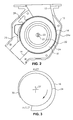
- FIG. 2 is a side view of a bulk materials pump feeder constructed in accordance with the present invention.
- FIG. 3 is a schematic drawing of the relationship between the drive discs and the inner wall of the housing of a bulk materials pump feeder constructed in accordance with the present invention.
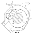
- FIG. 4 is a side view showing the relationship of the FIG. 1 drive rotor hub and the FIG. 1 materials scraper.
- FIG. 5 is a side view showing the relationship of the FIG. 1 drive rotor hub and a second materials scraper.
- a bulk materials pump feeder constructed in accordance with the present invention, includes an housing 10 having an inlet 12 , an outlet 14 , and an inner wall 16 extending from inlet 12 to outlet 14 .
- a bulk materials pump feeder constructed in accordance with the present invention, is generally similar in construction and operation to the units described and illustrated in U.S. Pat. No. 5,051,041 and U.S. Pat. No. 5,355,993, the contents of which are incorporated herein by reference.
- the bulk materials pump feeder of FIGS. 1 and 2 also has a drive rotor 18 having a hub 20 that is rotatable about a rotation axis 22 and a pair of drive discs 24 which extend away from the hub toward inner wall 16 of housing 10 .
- hub 20 and drive discs 24 are formed as a single unit.
- Drive discs 24 can be formed with radially extending discontinuities on the interior faces as described and illustrated in U.S. Pat. No. 5,355,993 to facilitate transfer of material from inlet 12 of housing 10 to outlet 14 of the housing.
- the outside surfaces of drive discs 24 each have a bevel 24 a at the circumferential edge of the drive disc for a reason to be explained below.
- Drive rotor 18 is mounted in housing 10 for rotation about rotation axis 22 and is held in place by, for example, a screw 25 .
- drive rotor 18 has two drive discs 24 .
- Drive rotor 18 can be arranged to have more than two drive discs. The number of drive discs to be included in the drive rotor is dependent on the particular application of bulk materials pump feeder (i.e., materials being transferred, performance specifications, etc.).
- FIG. 3 is a schematic drawing of the relationship between drive discs 24 and inner wall 16 of housing 10
- the distance between the circumferential edges of the drive discs and the inner wall of the housing increases from the INLET of the housing to the OUTLET of the housing in the direction of rotation of the drive rotor, which is clockwise as indicated by the arrow for the embodiment of the invention illustrated in the drawings and being described.
- the drive discs and the inner wall of the housing can be shaped in different ways to provide the desired spacing between the two.
- drive discs 24 are circular and extend away from hub 20 perpendicular to rotation axis 22 of the hub and inner wall 16 of housing 10 is spiral shaped.
- the spiral shaped inner wall 16 of housing 10 can be defined by the Archimedes spiral equation:
- a is the rate of radial increase given in some unit of measure per angular unit, such as mm/degree
- the desired increasing distance between the circumferential edges of the drive discs and the inner wall of the housing is effected by the spiral shape of the inner wall of the housing.
- This desired increasing distance between the circumferential edges of the drive discs and the inner wall of the housing also can be effected by the design of the drive discs or by a combination of the design of the drive discs and the design of the inner wall of the housing.
- Inner wall 16 of housing 10 , the inside surfaces of drive discs 24 , and hub 20 define a materials transfer duct through which material is transferred from inlet 12 of the housing to outlet 14 of the housing.
- drive rotor 18 is rotated by a motor (not shown) coupled to the drive rotor by suitable means, drive discs 24 cause material, introduced into the bulk materials pump feeder through inlet 12 of housing 10 , to be transferred to outlet 14 of the housing where the material is discharged from the bulk materials pump feeder.
- a bulk materials pump feeder constructed in accordance with the present invention, preferably includes a materials scraper 26 that is mounted in a recess 28 in inner wall 16 of housing 10 downstream from outlet 14 and upstream from inlet 12 .
- Materials scraper 26 extends into drive rotor 18 in the space between the interior faces of drive discs 24 almost touching hub 20 .
- Materials scraper 28 has two surfaces 30 (only one is illustrated in FIG. 1) that face the circumferential edges of drive discs 24 .
- the distance between surfaces 30 of the materials scraper and the circumferential edges of the drive discs increases in the direction of rotation of drive rotor 18 from the distance between inner wall 16 of housing 10 and the circumferential edges of drive discs at outlet 14 of the housing to the distance between the inner wall of the housing and the circumferential edges of the drive discs at inlet 12 of the housing.
- surfaces 30 of materials scraper 26 are, in effect, continuations of inner wall 16 of the housing, so that material that is not discharged at outlet 14 that tends to wedge between the materials scraper and the circumferential edges of drive discs 24 moves in the direction of rotation of the drive rotor to a larger spacing between the drive discs and the materials scraper and either falls back and is discharged through the outlet or falls in with material that is introduced at the inlet 12 .
- the increasing space between surfaces 30 of materials scraper 26 and the circumferential edges of drive discs 24 is illustrated in FIG. 3.
- Materials scraper 26 that is illustrated in FIGS. 1 and 4 has a plurality of scraping tips 26 a , 26 b , and 26 c that scrape material that is not discharged at outlet 14 .
- the spacing between materials scraper 26 and hub 20 specifically the spacing between scraping tips 26 a , 26 b , and 26 c and the hub, increases in the direction of rotation of drive rotor 18 from outlet 14 to inlet 12 to reduce, or even eliminate, the tendency of material to wedge between the scraper and the hub.
- Scraping tips 26 a , 26 b , and 26 c can be points on a spiral or simply points that are spaced from hub 20 the desired distances.
- FIG. 5 A second form of materials scraper is illustrated in FIG. 5.
- Scraper 26 ′ of FIG. 5 has a continuous scraping surface, rather than a plurality of scraping tips as in materials scraper 26 shown in FIG. 4.
- the spacing between the scraping surface of materials scraper 26 ′ and hub 20 increases in the direction of rotation of the from outlet 14 to inlet 12 to reduce, or even eliminate, the tendency of material to wedge between the scraper and the hub.
- the scraping surface of materials scraper 26 ′ can be spiral shaped.
Landscapes
- Engineering & Computer Science (AREA)
- Mechanical Engineering (AREA)
- General Engineering & Computer Science (AREA)
- Filling Or Emptying Of Bunkers, Hoppers, And Tanks (AREA)
- Rotary Pumps (AREA)
Abstract
Description
- The present invention relates, in general, to materials handling equipment and, in particular, to a pump feeder of materials handling equipment that feeds bulk materials.
- In certain bulk materials handling equipment, such as the equipment described and illustrated in U.S. Pat. No. 5,051,041 and U.S. Pat. No. 5,355,993, a pump feeder moves bulk material through a housing from an inlet to an outlet by a rotating drive rotor having two or more drive discs mounted to or integral with a rotating hub. In the past, this type of equipment has been used for feeding coal and other breakable material having uniform and non-uniform gradation. Typically, the drive systems for this equipment have delivered large torque at slow speed.
- As such equipment is adapted to handle different materials supplied in different sizes, problems that have not been encountered previously are arising. One such problem of major importance is the tendency of smaller size equipment, handling harder, smaller size material such as plastic, to stall, sometimes only temporarily, as the material being handled wedges between the rotating drive rotor and the housing or stationary parts mounted to the housing. This wedging of material can occur, for example, between the drive discs of the drive rotor and the housing inner wall or between the hub of the drive rotor and a materials scraper mounted to the inner wall of the housing.
- Simply increasing the drive power (i.e., providing a larger drive motor) to overcome the wedging is not, in most instances, an adequate or satisfactory solution to the problem. Cost and space limitations are but two restrictions on simply providing increased drive power. Certain of the materials being handled are not easily breakable, so a larger drive motor simply increases the effect of the material wedging between the rotating drive rotor and the housing or stationary parts mounted to the housing. This can result in a complete stoppage of operation and damage to the equipment. With breakable materials, such coal, the drive torque is large enough to break or pulverize the material into smaller pieces that do not wedge between the rotating drive rotor and the housing or stationary parts mounted to the housing.
- Although this adverse wedging effect might not be a regular occurrence and is likely to be different for handling different types of material, when it does occur, even temporarily, it affects accuracy and feeder performance to an unacceptable extent. Because the tendency of the equipment to stall, either temporarily or for longer periods of time, due to this wedging is greater at higher speed operation of the equipment, slowing down the operation of the equipment to reduce the likelihood of material wedging, while possibly reducing the likelihood of wedging, also is unacceptable.
- A bulk materials pump feeder, constructed in accordance with the present invention, includes a housing having an inlet, an outlet, and an inner wall extending from the inlet of the housing to the outlet of the housing. This bulk materials pump feeder also includes a drive rotor having a hub rotatable about a rotation axis and a plurality of drive discs extending away from the hub toward the inner wall of the housing. The distance between the circumferential edges of the drive discs and the inner wall of the housing increases from the inlet of the housing to the outlet of the housing in the direction of rotation of the drive rotor. The inner wall of the housing, the drive discs, and the hub define a materials transfer duct through which material is transferred from the inlet of the housing to the outlet of the housing.
- The present invention is best understood from the following detailed description when read in connection with the accompanying drawings. Included in the drawings are the following figures.
- FIG. 1 is an exploded, perspective view of a bulk materials pump feeder constructed in accordance with the present invention.
- FIG. 2 is a side view of a bulk materials pump feeder constructed in accordance with the present invention.
- FIG. 3 is a schematic drawing of the relationship between the drive discs and the inner wall of the housing of a bulk materials pump feeder constructed in accordance with the present invention.
- FIG. 4 is a side view showing the relationship of the FIG. 1 drive rotor hub and the FIG. 1 materials scraper.
- FIG. 5 is a side view showing the relationship of the FIG. 1 drive rotor hub and a second materials scraper.
- Referring to FIGS. 1 and 2, a bulk materials pump feeder, constructed in accordance with the present invention, includes an
housing 10 having aninlet 12, anoutlet 14, and aninner wall 16 extending frominlet 12 tooutlet 14. A bulk materials pump feeder, constructed in accordance with the present invention, is generally similar in construction and operation to the units described and illustrated in U.S. Pat. No. 5,051,041 and U.S. Pat. No. 5,355,993, the contents of which are incorporated herein by reference. - The bulk materials pump feeder of FIGS. 1 and 2 also has a
drive rotor 18 having ahub 20 that is rotatable about arotation axis 22 and a pair ofdrive discs 24 which extend away from the hub towardinner wall 16 ofhousing 10. For the embodiment of the invention being described,hub 20 anddrive discs 24 are formed as a single unit.Drive discs 24 can be formed with radially extending discontinuities on the interior faces as described and illustrated in U.S. Pat. No. 5,355,993 to facilitate transfer of material frominlet 12 ofhousing 10 tooutlet 14 of the housing. Preferably, the outside surfaces ofdrive discs 24 each have abevel 24 a at the circumferential edge of the drive disc for a reason to be explained below. -
Drive rotor 18 is mounted inhousing 10 for rotation aboutrotation axis 22 and is held in place by, for example, ascrew 25. For the embodiment of the invention illustrated in the drawings and being described,drive rotor 18 has twodrive discs 24.Drive rotor 18 can be arranged to have more than two drive discs. The number of drive discs to be included in the drive rotor is dependent on the particular application of bulk materials pump feeder (i.e., materials being transferred, performance specifications, etc.). - As shown most clearly in FIG. 3, which is a schematic drawing of the relationship between
drive discs 24 andinner wall 16 ofhousing 10, the distance between the circumferential edges of the drive discs and the inner wall of the housing increases from the INLET of the housing to the OUTLET of the housing in the direction of rotation of the drive rotor, which is clockwise as indicated by the arrow for the embodiment of the invention illustrated in the drawings and being described. The drive discs and the inner wall of the housing can be shaped in different ways to provide the desired spacing between the two. For the embodiment of the invention illustrated in the drawings and being described, drivediscs 24 are circular and extend away fromhub 20 perpendicular torotation axis 22 of the hub andinner wall 16 ofhousing 10 is spiral shaped. The spiral shapedinner wall 16 ofhousing 10 can be defined by the Archimedes spiral equation: - R=θ*a
- where:
- “R” is the radius
- “θ” is the polar angle
- “a” is the rate of radial increase given in some unit of measure per angular unit, such as mm/degree
- The distance between the circumferential edges of the drive discs and the inner wall of the housing is exaggerated in FIG. 3 for purposes of illustration.
- For the embodiment of the present invention represented by FIG. 3, the desired increasing distance between the circumferential edges of the drive discs and the inner wall of the housing is effected by the spiral shape of the inner wall of the housing. This desired increasing distance between the circumferential edges of the drive discs and the inner wall of the housing also can be effected by the design of the drive discs or by a combination of the design of the drive discs and the design of the inner wall of the housing.
-
Inner wall 16 ofhousing 10, the inside surfaces ofdrive discs 24, andhub 20 define a materials transfer duct through which material is transferred frominlet 12 of the housing tooutlet 14 of the housing. Asdrive rotor 18 is rotated by a motor (not shown) coupled to the drive rotor by suitable means, drivediscs 24 cause material, introduced into the bulk materials pump feeder throughinlet 12 ofhousing 10, to be transferred tooutlet 14 of the housing where the material is discharged from the bulk materials pump feeder. Pieces of material being transferred through this bulk materials pump feeder from the inlet to the outlet that tend to wedge between the inner wall of the housing and the circumferential edges of the drive discs move in the direction of rotation of the drive rotor to a larger spacing between the circumferential edges of the drive discs and the inner wall of the housing and do not wedge because of the increasing space between the circumferential edges of the drive discs and the inner wall of the housing. Instead, this material is discharged throughoutlet 14. By beveling the outside surfaces ofdrive discs 24 at the circumferential edges, the surface areas of the circumferential edges of the drive discs are minimized, thereby reducing the tending of material to wedge between the drive discs and the inner wall of the housing. - Referring to FIGS. 1, 2, and 4, a bulk materials pump feeder, constructed in accordance with the present invention, preferably includes a
materials scraper 26 that is mounted in arecess 28 ininner wall 16 ofhousing 10 downstream fromoutlet 14 and upstream frominlet 12.Materials scraper 26 extends intodrive rotor 18 in the space between the interior faces ofdrive discs 24 almost touchinghub 20. - Certain materials that are transferred through the bulk materials pump feeder will, under certain conditions, cling to drive
rotor 18 and not be discharged throughoutlet 14. Materials scraper 26 scrapes such material from the drive rotor and, generally, this material falls back and is discharged through the outlet. -
Materials scraper 28 has two surfaces 30 (only one is illustrated in FIG. 1) that face the circumferential edges ofdrive discs 24. The distance betweensurfaces 30 of the materials scraper and the circumferential edges of the drive discs increases in the direction of rotation ofdrive rotor 18 from the distance betweeninner wall 16 ofhousing 10 and the circumferential edges of drive discs atoutlet 14 of the housing to the distance between the inner wall of the housing and the circumferential edges of the drive discs atinlet 12 of the housing. In particular, surfaces 30 of materials scraper 26 are, in effect, continuations ofinner wall 16 of the housing, so that material that is not discharged atoutlet 14 that tends to wedge between the materials scraper and the circumferential edges ofdrive discs 24 moves in the direction of rotation of the drive rotor to a larger spacing between the drive discs and the materials scraper and either falls back and is discharged through the outlet or falls in with material that is introduced at theinlet 12. The increasing space betweensurfaces 30 ofmaterials scraper 26 and the circumferential edges ofdrive discs 24, from the OUTLET to the INLET, is illustrated in FIG. 3. -
Materials scraper 26 that is illustrated in FIGS. 1 and 4 has a plurality of scrapingtips outlet 14. As illustrated in FIG. 4, the spacing betweenmaterials scraper 26 andhub 20, specifically the spacing between scrapingtips drive rotor 18 fromoutlet 14 toinlet 12 to reduce, or even eliminate, the tendency of material to wedge between the scraper and the hub.Scraping tips hub 20 the desired distances. - A second form of materials scraper is illustrated in FIG. 5.
Scraper 26′ of FIG. 5 has a continuous scraping surface, rather than a plurality of scraping tips as in materials scraper 26 shown in FIG. 4. The spacing between the scraping surface of materials scraper 26′ andhub 20 increases in the direction of rotation of the fromoutlet 14 toinlet 12 to reduce, or even eliminate, the tendency of material to wedge between the scraper and the hub. The scraping surface of materials scraper 26′ can be spiral shaped. - Although illustrated and described above with reference to certain specific embodiments, the present invention nevertheless is not intended to be limited to the details shown. Rather, various modifications may be made in the details within the scope and range of equivalents of the claims and without departing from the spirit of the invention.
Claims (20)
Priority Applications (13)
| Application Number | Priority Date | Filing Date | Title |
|---|---|---|---|
| US10/119,359 US6832887B2 (en) | 2002-04-09 | 2002-04-09 | Bulk material pump feeder |
| DE60332447T DE60332447D1 (en) | 2002-04-09 | 2003-03-17 | PUMP FEEDING DEVICE FOR BULK GOODS |
| CNB038080214A CN100370144C (en) | 2002-04-09 | 2003-03-17 | Bulk Material Feed Pumps |
| EP03716571A EP1495230B1 (en) | 2002-04-09 | 2003-03-17 | Bulk material pump feeder |
| BRPI0309141-4A BR0309141B1 (en) | 2002-04-09 | 2003-03-17 | BULK MATERIAL PUMP FEEDER |
| KR1020047016086A KR100953893B1 (en) | 2002-04-09 | 2003-03-17 | Bulk material pump feeder |
| KR1020097026598A KR100984495B1 (en) | 2002-04-09 | 2003-03-17 | Bulk material pump feeder |
| AU2003220273A AU2003220273A1 (en) | 2002-04-09 | 2003-03-17 | Bulk material pump feeder |
| JP2003584500A JP4649110B2 (en) | 2002-04-09 | 2003-03-17 | Granule pump feeder |
| PCT/US2003/007869 WO2003087580A1 (en) | 2002-04-09 | 2003-03-17 | Bulk material pump feeder |
| US10/625,253 US7044288B2 (en) | 2002-04-09 | 2003-07-23 | Bulk material pump feeder with reduced disk jamming |
| US11/384,797 US7303062B2 (en) | 2002-04-09 | 2006-03-20 | Bulk material pump feeder with reduced disk jamming |
| US11/947,486 US8083051B2 (en) | 2002-04-09 | 2007-11-29 | Bulk material pump feeder with reduced disk jamming |
Applications Claiming Priority (1)
| Application Number | Priority Date | Filing Date | Title |
|---|---|---|---|
| US10/119,359 US6832887B2 (en) | 2002-04-09 | 2002-04-09 | Bulk material pump feeder |
Related Child Applications (1)
| Application Number | Title | Priority Date | Filing Date |
|---|---|---|---|
| US10/625,253 Continuation-In-Part US7044288B2 (en) | 2002-04-09 | 2003-07-23 | Bulk material pump feeder with reduced disk jamming |
Publications (2)
| Publication Number | Publication Date |
|---|---|
| US20030190198A1 true US20030190198A1 (en) | 2003-10-09 |
| US6832887B2 US6832887B2 (en) | 2004-12-21 |
Family
ID=28674573
Family Applications (1)
| Application Number | Title | Priority Date | Filing Date |
|---|---|---|---|
| US10/119,359 Expired - Lifetime US6832887B2 (en) | 2002-04-09 | 2002-04-09 | Bulk material pump feeder |
Country Status (9)
| Country | Link |
|---|---|
| US (1) | US6832887B2 (en) |
| EP (1) | EP1495230B1 (en) |
| JP (1) | JP4649110B2 (en) |
| KR (2) | KR100984495B1 (en) |
| CN (1) | CN100370144C (en) |
| AU (1) | AU2003220273A1 (en) |
| BR (1) | BR0309141B1 (en) |
| DE (1) | DE60332447D1 (en) |
| WO (1) | WO2003087580A1 (en) |
Cited By (5)
| Publication number | Priority date | Publication date | Assignee | Title |
|---|---|---|---|---|
| US20070084700A1 (en) * | 2005-10-12 | 2007-04-19 | K-Tron Technologies, Inc. | Bulk material pump feeder with reduced disk jamming, compliant disks |
| US20080142340A1 (en) * | 2002-04-09 | 2008-06-19 | K-Tron Technologies, Inc | Bulk Material Pump Feeder with Reduced Disk Jamming |
| US9206806B1 (en) * | 2014-08-05 | 2015-12-08 | General Electric Company | Solids pump having feed guides |
| CN113195901A (en) * | 2018-12-21 | 2021-07-30 | 格兰富控股联合股份公司 | Centrifugal pump with scraper |
| US11607667B2 (en) | 2017-11-16 | 2023-03-21 | Nippon Shokubai Co., Ltd. | Absorption agent and absorbent article |
Families Citing this family (17)
| Publication number | Priority date | Publication date | Assignee | Title |
|---|---|---|---|---|
| US7485672B2 (en) * | 2001-08-02 | 2009-02-03 | Johnson & Johnson Vision Care, Inc. | Process for the synthesis of soluble, high molecular weight polymers |
| US7879267B2 (en) | 2001-08-02 | 2011-02-01 | J&J Vision Care, Inc. | Method for coating articles by mold transfer |
| WO2009009189A2 (en) * | 2007-04-20 | 2009-01-15 | General Electric Company | Transporting particulate material |
| WO2008152048A1 (en) * | 2007-06-13 | 2008-12-18 | Shell Internationale Research Maatschappij B.V. | Bulk materials pump and its use |
| US8651772B2 (en) * | 2007-12-20 | 2014-02-18 | General Electric Company | Rotary apparatus for use with a gasifier system and methods of using the same |
| US7883583B2 (en) * | 2008-01-08 | 2011-02-08 | Global Oled Technology Llc | Vaporization apparatus with precise powder metering |
| US7972443B2 (en) * | 2008-11-14 | 2011-07-05 | Global Oled Technology Llc | Metering of particulate material and vaporization thereof |
| US8048230B2 (en) * | 2008-11-14 | 2011-11-01 | Global Oled Technology Llc | Metering and vaporizing particulate material |
| US8062427B2 (en) * | 2008-11-14 | 2011-11-22 | Global Oled Technology Llc | Particulate material metering and vaporization |
| US20100206234A1 (en) * | 2009-02-17 | 2010-08-19 | Michael Long | Simplified powder feeding and vaporization apparatus |
| US8579103B2 (en) * | 2011-10-03 | 2013-11-12 | General Electric Company | System and method for transporting solid feed in a solid feed pump |
| US9022723B2 (en) * | 2012-03-27 | 2015-05-05 | General Electric Company | System for drawing solid feed into and/or out of a solid feed pump |
| US9004265B2 (en) | 2012-04-18 | 2015-04-14 | General Electric Company | Methods for restricting backflow of solids in a pump assembly |
| DE102013206482A1 (en) | 2013-04-11 | 2014-10-30 | Alfons Tschritter Gmbh | Dosing device for bulk material particles |
| US9604182B2 (en) * | 2013-12-13 | 2017-03-28 | General Electric Company | System for transporting solids with improved solids packing |
| DE102015201840A1 (en) | 2015-02-03 | 2016-08-04 | Alfons Tschritter Gmbh | Dosing process and dosing device for bulk material particles |
| WO2019123053A1 (en) * | 2017-12-22 | 2019-06-27 | Pirelli Tyre S.P.A. | Metering apparatus for metering ingredients of compounds in particular for tyres and method for metering ingredients of compounds in particular for tyres |
Citations (10)
| Publication number | Priority date | Publication date | Assignee | Title |
|---|---|---|---|---|
| US2632399A (en) * | 1947-10-30 | 1953-03-24 | Hyre Warren | Rotary pump |
| US2868351A (en) * | 1955-03-28 | 1959-01-13 | Hegmann William George | Material thrower or impactor |
| US3245613A (en) * | 1962-12-17 | 1966-04-12 | Combustion Eng | Centrifuge outlet |
| US3787093A (en) * | 1970-10-12 | 1974-01-22 | Rieter Ag Maschf | Apparatus for separating fiber flocks from a transporting air stream |
| US4826401A (en) * | 1981-07-02 | 1989-05-02 | Tmt Research Development Inc. | Centrifugal pump |
| US5186604A (en) * | 1991-12-23 | 1993-02-16 | The United States Of America As Represented By The Secretary Of The Navy | Electro-rheological disk pump |
| US6213289B1 (en) * | 1997-11-24 | 2001-04-10 | Stamet, Incorporation | Multiple channel system, apparatus and method for transporting particulate material |
| US6375412B1 (en) * | 1999-12-23 | 2002-04-23 | Daniel Christopher Dial | Viscous drag impeller components incorporated into pumps, turbines and transmissions |
| US6431831B1 (en) * | 1999-08-20 | 2002-08-13 | Giw Industries, Inc. | Pump impeller with enhanced vane inlet wear |
| US6575695B1 (en) * | 1999-11-30 | 2003-06-10 | Maruyama Mfg. Co., Inc. | Centrifugal blower and power working machine |
Family Cites Families (17)
| Publication number | Priority date | Publication date | Assignee | Title |
|---|---|---|---|---|
| US1061142A (en) | 1909-10-21 | 1913-05-06 | Nikola Tesla | Fluid propulsion |
| US3920116A (en) | 1974-04-29 | 1975-11-18 | Technovators Inc | Impeller loading device |
| JPS5310453Y2 (en) * | 1976-03-31 | 1978-03-20 | ||
| US4516674A (en) | 1981-07-20 | 1985-05-14 | Donald Firth | Method and apparatus for conveying and metering solid material |
| US5190140A (en) | 1989-08-01 | 1993-03-02 | J-Star Industries | Material handling apparatus |
| US5051041A (en) | 1990-03-05 | 1991-09-24 | Stamet, Inc. | Multiple-choke apparatus for transporting and metering particulate material |
| US4988239A (en) | 1990-03-05 | 1991-01-29 | Stamet, Inc. | Multiple-choke apparatus for transporting and metering particulate material |
| IT1252103B (en) | 1991-11-27 | 1995-06-02 | Gpw Macchine S A S Di Giuseppe | PUMP FOR SPECIAL SOLID MATERIALS |
| US5551553A (en) | 1992-08-11 | 1996-09-03 | Stamet, Inc. | Angled disk drive apparatus for transporting and metering particulate material |
| US5355993A (en) * | 1993-06-11 | 1994-10-18 | Hay Andrew G | Grooved disk drive apparatus and method for transporting and metering particulate material |
| US5533650A (en) | 1993-07-21 | 1996-07-09 | Stamet, Inc. | Hopper with moving wall and method of making and using the same |
| US5485909A (en) | 1993-08-31 | 1996-01-23 | Stamet, Inc. | Apparatus with improved inlet and method for transporting and metering particulate material |
| CN2173768Y (en) * | 1993-09-01 | 1994-08-10 | 邱瑞东 | High-efficiency air jet pump |
| US5497873A (en) | 1993-12-08 | 1996-03-12 | Stamet, Inc. | Apparatus and method employing an inlet extension for transporting and metering fine particulate and powdery material |
| AU5295496A (en) | 1995-02-01 | 1996-08-27 | Stamet, Inc. | Method and system for handling and transporting hot ash and particulate material and controlling the bed of a fluidized bed apparatus |
| JP3653972B2 (en) | 1998-02-19 | 2005-06-02 | 三菱電機株式会社 | Electric fuel pump |
| CN2353940Y (en) * | 1998-09-15 | 1999-12-15 | 郑德明 | Low-pressure pneumatic continuous delivery pump |
-
2002
- 2002-04-09 US US10/119,359 patent/US6832887B2/en not_active Expired - Lifetime
-
2003
- 2003-03-17 KR KR1020097026598A patent/KR100984495B1/en not_active Expired - Fee Related
- 2003-03-17 WO PCT/US2003/007869 patent/WO2003087580A1/en not_active Ceased
- 2003-03-17 AU AU2003220273A patent/AU2003220273A1/en not_active Abandoned
- 2003-03-17 JP JP2003584500A patent/JP4649110B2/en not_active Expired - Fee Related
- 2003-03-17 KR KR1020047016086A patent/KR100953893B1/en not_active Expired - Lifetime
- 2003-03-17 DE DE60332447T patent/DE60332447D1/en not_active Expired - Lifetime
- 2003-03-17 BR BRPI0309141-4A patent/BR0309141B1/en not_active IP Right Cessation
- 2003-03-17 EP EP03716571A patent/EP1495230B1/en not_active Expired - Lifetime
- 2003-03-17 CN CNB038080214A patent/CN100370144C/en not_active Expired - Lifetime
Patent Citations (10)
| Publication number | Priority date | Publication date | Assignee | Title |
|---|---|---|---|---|
| US2632399A (en) * | 1947-10-30 | 1953-03-24 | Hyre Warren | Rotary pump |
| US2868351A (en) * | 1955-03-28 | 1959-01-13 | Hegmann William George | Material thrower or impactor |
| US3245613A (en) * | 1962-12-17 | 1966-04-12 | Combustion Eng | Centrifuge outlet |
| US3787093A (en) * | 1970-10-12 | 1974-01-22 | Rieter Ag Maschf | Apparatus for separating fiber flocks from a transporting air stream |
| US4826401A (en) * | 1981-07-02 | 1989-05-02 | Tmt Research Development Inc. | Centrifugal pump |
| US5186604A (en) * | 1991-12-23 | 1993-02-16 | The United States Of America As Represented By The Secretary Of The Navy | Electro-rheological disk pump |
| US6213289B1 (en) * | 1997-11-24 | 2001-04-10 | Stamet, Incorporation | Multiple channel system, apparatus and method for transporting particulate material |
| US6431831B1 (en) * | 1999-08-20 | 2002-08-13 | Giw Industries, Inc. | Pump impeller with enhanced vane inlet wear |
| US6575695B1 (en) * | 1999-11-30 | 2003-06-10 | Maruyama Mfg. Co., Inc. | Centrifugal blower and power working machine |
| US6375412B1 (en) * | 1999-12-23 | 2002-04-23 | Daniel Christopher Dial | Viscous drag impeller components incorporated into pumps, turbines and transmissions |
Cited By (7)
| Publication number | Priority date | Publication date | Assignee | Title |
|---|---|---|---|---|
| US20080142340A1 (en) * | 2002-04-09 | 2008-06-19 | K-Tron Technologies, Inc | Bulk Material Pump Feeder with Reduced Disk Jamming |
| US8083051B2 (en) | 2002-04-09 | 2011-12-27 | K-Tron Technologies, Inc. | Bulk material pump feeder with reduced disk jamming |
| US20070084700A1 (en) * | 2005-10-12 | 2007-04-19 | K-Tron Technologies, Inc. | Bulk material pump feeder with reduced disk jamming, compliant disks |
| US7677864B2 (en) * | 2005-10-12 | 2010-03-16 | K-Tron Technologies, Inc. | Bulk material pump feeder with reduced disk jamming, compliant disks |
| US9206806B1 (en) * | 2014-08-05 | 2015-12-08 | General Electric Company | Solids pump having feed guides |
| US11607667B2 (en) | 2017-11-16 | 2023-03-21 | Nippon Shokubai Co., Ltd. | Absorption agent and absorbent article |
| CN113195901A (en) * | 2018-12-21 | 2021-07-30 | 格兰富控股联合股份公司 | Centrifugal pump with scraper |
Also Published As
| Publication number | Publication date |
|---|---|
| JP4649110B2 (en) | 2011-03-09 |
| JP2005522391A (en) | 2005-07-28 |
| EP1495230B1 (en) | 2010-05-05 |
| KR20050003354A (en) | 2005-01-10 |
| WO2003087580A1 (en) | 2003-10-23 |
| BR0309141A (en) | 2005-02-01 |
| EP1495230A1 (en) | 2005-01-12 |
| KR100953893B1 (en) | 2010-04-22 |
| DE60332447D1 (en) | 2010-06-17 |
| AU2003220273A1 (en) | 2003-10-27 |
| KR100984495B1 (en) | 2010-10-01 |
| US6832887B2 (en) | 2004-12-21 |
| KR20100003374A (en) | 2010-01-08 |
| BR0309141B1 (en) | 2014-04-22 |
| CN1646813A (en) | 2005-07-27 |
| CN100370144C (en) | 2008-02-20 |
Similar Documents
| Publication | Publication Date | Title |
|---|---|---|
| US6832887B2 (en) | Bulk material pump feeder | |
| US8083051B2 (en) | Bulk material pump feeder with reduced disk jamming | |
| US7677864B2 (en) | Bulk material pump feeder with reduced disk jamming, compliant disks | |
| CN103193067A (en) | Belt impeller feeder | |
| TWM652304U (en) | Spiral conveyor blade | |
| JP6489962B2 (en) | Slurry pump | |
| CN212100663U (en) | A cutting auger | |
| CA1076508A (en) | Arrangement in screw-conveyors for equalising the flow of material conveyed thereby | |
| JPH09196343A (en) | Rotary feeder | |
| JP2004250164A (en) | Biting preventing plate of hopper for screw conveyer |
Legal Events
| Date | Code | Title | Description |
|---|---|---|---|
| AS | Assignment |
Owner name: K-TRON TECHNOLOGIES, INC., DELAWARE Free format text: ASSIGNMENT OF ASSIGNORS INTEREST;ASSIGNORS:BAER, TIMOTHY R.;FOLEY, JAMES T.;REEL/FRAME:012789/0032 Effective date: 20020408 |
|
| STCF | Information on status: patent grant |
Free format text: PATENTED CASE |
|
| CC | Certificate of correction | ||
| FPAY | Fee payment |
Year of fee payment: 4 |
|
| REMI | Maintenance fee reminder mailed | ||
| FEPP | Fee payment procedure |
Free format text: PAT HOLDER NO LONGER CLAIMS SMALL ENTITY STATUS, ENTITY STATUS SET TO UNDISCOUNTED (ORIGINAL EVENT CODE: STOL); ENTITY STATUS OF PATENT OWNER: LARGE ENTITY |
|
| SULP | Surcharge for late payment | ||
| FPAY | Fee payment |
Year of fee payment: 8 |
|
| FPAY | Fee payment |
Year of fee payment: 12 |