US20030190193A1 - Automatic flood gate - Google Patents
Automatic flood gate Download PDFInfo
- Publication number
- US20030190193A1 US20030190193A1 US10/116,249 US11624902A US2003190193A1 US 20030190193 A1 US20030190193 A1 US 20030190193A1 US 11624902 A US11624902 A US 11624902A US 2003190193 A1 US2003190193 A1 US 2003190193A1
- Authority
- US
- United States
- Prior art keywords
- gate
- opening
- housing
- water
- jambs
- Prior art date
- Legal status (The legal status is an assumption and is not a legal conclusion. Google has not performed a legal analysis and makes no representation as to the accuracy of the status listed.)
- Granted
Links
- XLYOFNOQVPJJNP-UHFFFAOYSA-N water Substances O XLYOFNOQVPJJNP-UHFFFAOYSA-N 0.000 claims abstract description 82
- 230000000630 rising effect Effects 0.000 claims abstract description 56
- 238000010276 construction Methods 0.000 claims abstract description 48
- 230000002706 hydrostatic effect Effects 0.000 claims abstract description 13
- 230000006835 compression Effects 0.000 claims abstract description 3
- 238000007906 compression Methods 0.000 claims abstract description 3
- 239000002352 surface water Substances 0.000 claims description 52
- 230000004888 barrier function Effects 0.000 claims description 27
- 239000000463 material Substances 0.000 claims description 13
- 238000000034 method Methods 0.000 claims description 10
- 238000007789 sealing Methods 0.000 claims description 7
- 238000013459 approach Methods 0.000 claims description 2
- 241000283216 Phocidae Species 0.000 description 10
- 238000005188 flotation Methods 0.000 description 8
- 239000003643 water by type Substances 0.000 description 5
- XAGFODPZIPBFFR-UHFFFAOYSA-N aluminium Chemical compound [Al] XAGFODPZIPBFFR-UHFFFAOYSA-N 0.000 description 4
- 229910052782 aluminium Inorganic materials 0.000 description 4
- 239000011162 core material Substances 0.000 description 4
- 230000008901 benefit Effects 0.000 description 3
- 238000009434 installation Methods 0.000 description 3
- 230000033001 locomotion Effects 0.000 description 3
- 238000012423 maintenance Methods 0.000 description 3
- 230000007246 mechanism Effects 0.000 description 3
- 238000001363 water suppression through gradient tailored excitation Methods 0.000 description 3
- 238000009412 basement excavation Methods 0.000 description 2
- 238000004140 cleaning Methods 0.000 description 2
- 239000002131 composite material Substances 0.000 description 2
- 238000005192 partition Methods 0.000 description 2
- 241000233866 Fungi Species 0.000 description 1
- 241000282414 Homo sapiens Species 0.000 description 1
- 241000283139 Pusa sibirica Species 0.000 description 1
- 230000009471 action Effects 0.000 description 1
- 238000007792 addition Methods 0.000 description 1
- 230000003466 anti-cipated effect Effects 0.000 description 1
- 238000005260 corrosion Methods 0.000 description 1
- 230000007797 corrosion Effects 0.000 description 1
- 230000007123 defense Effects 0.000 description 1
- 230000003028 elevating effect Effects 0.000 description 1
- 239000006260 foam Substances 0.000 description 1
- 239000000446 fuel Substances 0.000 description 1
- 239000010438 granite Substances 0.000 description 1
- 230000005484 gravity Effects 0.000 description 1
- 230000009545 invasion Effects 0.000 description 1
- 238000004806 packaging method and process Methods 0.000 description 1
- 230000035515 penetration Effects 0.000 description 1
- 229920002635 polyurethane Polymers 0.000 description 1
- 239000004814 polyurethane Substances 0.000 description 1
- 230000001105 regulatory effect Effects 0.000 description 1
- 239000012858 resilient material Substances 0.000 description 1
- 230000004044 response Effects 0.000 description 1
- 239000003566 sealing material Substances 0.000 description 1
- 238000000926 separation method Methods 0.000 description 1
- 230000002459 sustained effect Effects 0.000 description 1
- 238000005406 washing Methods 0.000 description 1
Images


Classifications
-
- E—FIXED CONSTRUCTIONS
- E02—HYDRAULIC ENGINEERING; FOUNDATIONS; SOIL SHIFTING
- E02B—HYDRAULIC ENGINEERING
- E02B3/00—Engineering works in connection with control or use of streams, rivers, coasts, or other marine sites; Sealings or joints for engineering works in general
- E02B3/04—Structures or apparatus for, or methods of, protecting banks, coasts, or harbours
- E02B3/10—Dams; Dykes; Sluice ways or other structures for dykes, dams, or the like
- E02B3/102—Permanently installed raisable dykes
- E02B3/104—Permanently installed raisable dykes with self-activating means
-
- E—FIXED CONSTRUCTIONS
- E02—HYDRAULIC ENGINEERING; FOUNDATIONS; SOIL SHIFTING
- E02B—HYDRAULIC ENGINEERING
- E02B7/00—Barrages or weirs; Layout, construction, methods of, or devices for, making same
- E02B7/20—Movable barrages; Lock or dry-dock gates
- E02B7/205—Barrages controlled by the variations of the water level; automatically functioning barrages
-
- E—FIXED CONSTRUCTIONS
- E02—HYDRAULIC ENGINEERING; FOUNDATIONS; SOIL SHIFTING
- E02B—HYDRAULIC ENGINEERING
- E02B7/00—Barrages or weirs; Layout, construction, methods of, or devices for, making same
- E02B7/20—Movable barrages; Lock or dry-dock gates
- E02B7/40—Swinging or turning gates
- E02B7/44—Hinged-leaf gates
-
- E—FIXED CONSTRUCTIONS
- E02—HYDRAULIC ENGINEERING; FOUNDATIONS; SOIL SHIFTING
- E02B—HYDRAULIC ENGINEERING
- E02B7/00—Barrages or weirs; Layout, construction, methods of, or devices for, making same
- E02B7/20—Movable barrages; Lock or dry-dock gates
- E02B7/50—Floating gates
-
- E—FIXED CONSTRUCTIONS
- E02—HYDRAULIC ENGINEERING; FOUNDATIONS; SOIL SHIFTING
- E02B—HYDRAULIC ENGINEERING
- E02B7/00—Barrages or weirs; Layout, construction, methods of, or devices for, making same
- E02B7/20—Movable barrages; Lock or dry-dock gates
- E02B7/54—Sealings for gates
-
- E—FIXED CONSTRUCTIONS
- E06—DOORS, WINDOWS, SHUTTERS, OR ROLLER BLINDS IN GENERAL; LADDERS
- E06B—FIXED OR MOVABLE CLOSURES FOR OPENINGS IN BUILDINGS, VEHICLES, FENCES OR LIKE ENCLOSURES IN GENERAL, e.g. DOORS, WINDOWS, BLINDS, GATES
- E06B9/00—Screening or protective devices for wall or similar openings, with or without operating or securing mechanisms; Closures of similar construction
- E06B9/02—Shutters, movable grilles, or other safety closing devices, e.g. against burglary
- E06B9/04—Shutters, movable grilles, or other safety closing devices, e.g. against burglary of wing type, e.g. revolving or sliding
-
- E—FIXED CONSTRUCTIONS
- E06—DOORS, WINDOWS, SHUTTERS, OR ROLLER BLINDS IN GENERAL; LADDERS
- E06B—FIXED OR MOVABLE CLOSURES FOR OPENINGS IN BUILDINGS, VEHICLES, FENCES OR LIKE ENCLOSURES IN GENERAL, e.g. DOORS, WINDOWS, BLINDS, GATES
- E06B9/00—Screening or protective devices for wall or similar openings, with or without operating or securing mechanisms; Closures of similar construction
- E06B2009/007—Flood panels
Definitions
- This invention generally relates to method and apparatus for regulating the flow of water, more particularly, to water gates, and especially water gates in which the water gate turns about a pivot axis which is generally parallel to the horizon.
- standby power generators and/or fuel powered water evacuation pumps are located below surface grade, such as in a basement, as all too often is the case, the power generators and water pumps can be disabled by water flooding into an area where they are located, removing often the last line of flood defense of the building.
- Openings to buildings through which rising water can invade include entrances to covered receiving and loading docks, to underground parking areas and garages, to descending stairwells, and to vents, and potential entrances include grade-level and below grade windows or doors.
- Bottom-hinged “flip-up” flood gates, with inflatable gaskets, that are floor recessed when not in use, that have an exposed surface for traffic passage, and that are raised by hydraulic cylinders or winches, are commercially available.
- Other also not automatic building water barriers are shown in U.S. Pat. No. 5,943,832 for flood or storm resistant barriers for doorways or window opening; U.S. Pat. No. 5,283,979 for locking/opening system for watertight hatch, U.S. Pat. No. 4,582,451 for floodgate panel and sealing means therefor; and U.S. Pat. No. 4,355,000 for lightweight, removable gate seal.
- the building structure itself or buried ancillary structure prevents excavations to a depth needed for placement of a vertical barrier.
- a flood recedes, mud and flood debris from the water remain, and removal of debris from a tall, thin vertical slot in the ground, occluded with the flotation barrier, presents maintenance difficulties.
- U.S. Pat. No. 4,377,352 issued Mar. 22, 1983 to Goodstein, describes a self-actuating water containment barrier for guarding open fields along flooding streams or rising lakes.
- the barrier comprises a plurality of stanchions which are mounted for pivotal movement from a normal dormant horizontal position, to an active vertical position.
- the stanchions are interconnected with water barrier-forming sheeting to form a barrier which can conform to a particular land mass or shoreline.
- Float members are mounted on the bottom of the outer ends of the stanchions. At low water levels, the float members rest on a shallow body of water or on the ground in a near horizontal position.
- This invention provides a flood guard method and apparatus for automatically refusing admission of rising surface water into a structural opening of a construction.
- construction is meant any structure, building, erection, edifice or the like, and includes interior and exterior partitions and walls, in which openings such as doors or windows may occur, for passage from outside the construction to its interior, or within the construction from one room to another, or from one side of a partition to the other side, and this includes elongated passages such as tunnels and halls.
- the construction and the opening in the construction may be at ground level or below ground level, such as an underground parking garage, a basement, a subterranean tunnel or other subterranean space, so long as access to the construction or from one part of the construction to another is by an opening through which water can flow under the force of gravity.
- the essential factor is that the invention guards against flooding from surface water through an opening to the construction.
- the invention involves (i) pivoting a buoyant and structurally rigid flood gate from adjacent grade about an axis at the base of the gate arranged adjacent the bottom of a construction opening generally parallel to grade, such that, on rise of surface water sufficient to float the gate, the gate is buoyed and by force of rising water is rotated about the pivot axis in the direction of the opening, and (ii) as the gate buoyantly rotates upwardly, preventing the rising water from flowing around the sides of the gate sufficiently that enough hydraulic pressure is impressed on the gate by the rising water to push the gate into closing contact with stops or jambs adjacent the sides of the opening, thereby closing the opening and barring admission of flood water into the construction.
- this invention provides a method for automatically refusing admission of rising surface water into a structural opening of a construction, the opening having opening-limiting margins, including a bottom, sides and usually a top.
- the method comprises (a) housing a buoyant gate of dimension occlusive to at least a lower portion of the opening adjacently in front of the opening, substantially parallel to grade, pivotingly arranged about a pivot axis parallel to the bottom of the opening and in a recess into which surface water can flow, (b) providing a portal for admitting surface water into the recess to cause the gate to pivotingly buoy upwardly from the recess in a rotation closing towards the opening, and (c) preventing rising surface water from flowing around sides of the upwardly buoyed gate, whereby rising surface water accumulates behind the gate and hydraulic pressure of the rising surface water exerts a continuing closing force rotating the gate toward, thence occlusively across, at least a lower portion of the opening.
- a self actuating flood guard for refusing admission of rising surface water into a structural opening of a construction, the opening having opening-limiting margins, including a bottom, sides and usually a top comprises (1) a buoyant gate having a base, sides, a front, a back and dimensions occlusive of at least a lower portion of the opening, the base being arranged for location adjacent the bottom of the opening, (2) pivotation members hinging the gate at the base about a pivot axis parallel to the bottom of the opening and allowing the gate to rest substantially parallel and adjacent grade proximately in front of the opening for pivotation upwardly toward and transversely to the opening, (3) a pair of upright walls reaching from grade and extending alongside the sides of the gate at rest, the walls having facing surfaces spaced apart sufficiently to allow the gate to pivot upwardly between them toward the opening with the sides of the gate close enough to the facing wall surfaces to permit hydrostatic pressure of surface water rising from the grade to develop against
- the flood guard advantageously comprises a housing for the gate and pivotation members, the housing including a floor and sides for containing the gate above the floor such that with the gate resident in the housing the front of the gate substantially closes the gate housing.
- the gate is weight bearing, and when resident in the housing, it provides a passageway for traffic into the construction through the opening.
- the gate housing further comprises a surface water portal into the housing giving access to the floor of the housing when the gate is resident in the housing, the housing and gate being configured to permit surface water entering through the portal to rise beneath the gate and pivotingly buoy the gate upwardly from the housing for rotation about the axis toward the opening.
- the portal is located in the housing at least adjacent the location in the housing remote from where the base of the gate is pivoted.
- a drain is provided in the gate housing to remove waters flowing into the housing.
- the removed water is emptied to a storm water collector tributary such as storm sewer, ditch, canal or other water collecting and removal system, including return to streets to discharge from the street to ditches or to storm sewers accessed by inlets along the sides of the streets.
- the purpose of the drain is to prevent the gate from floating up and out of its housing on the occasion of a heavy downpour which has not become a flooding situation. So long as the storm sewer or other water collector system is not full, water will not back up in the drain but will flow out and be removed by the water collector system.
- seals affixed to the sides of the gate sealingly closing the gaps between the sides of the gate and the facing wall surfaces during rotation of the gate toward the opening of the construction.
- the seals are contact seals, preferably of a type that compress when brought into engagement with the walls during rotation toward the opening.
- the jambs are affixed to the upright walls adjacent the opening and reach upwardly from adjacent grade.
- the jambs may reach an elevation proximate the height of the upright walls adjacent the opening, and may and preferably do include a resilient sealing surface arranged to cooperate with facing surfaces of the front of the gate in the closed position to seal against admission of water between the jamb and the gate.
- the gate comprises buoyant material, for example, it may comprise a plurality of sealed tubes arranged side by side, or a honeycomb core structure sealingly arranged between two rigid panels. Alternatively the gate may have a bladder for a flotation material.
- the jambs may be affixed to the construction on the sides of the opening.
- the jambs may be freestanding from grade level or may project toward the opening from the upright walls, but the jambs are always spaced apart not more than the spacing of facing surfaces of the walls.
- the jambs are arranged with respect to the construction to act as a barrage to water between the jambs and the construction.
- the walls are arranged relative to the construction to form a barrage to water between the walls and the construction.
- the upright walls extend from the construction and in cooperation with the jambs and the gate in the closed position provide a barrage to water between the walls and the construction.
- the invention works either where the grade on which it is installed is horizontal or is angled relative to horizontal, either declined or inclined.
- the construction may be a parking garage with underground parking accessed by a downwardly sloped ramp in which the flood guard may be installed.
- the system of the invention is completely passive and automatic. There is no power or maintenance requirement and the gate normally rests out of the way so that once it is installed, most people passing or driving over it don't even realize it is there.
- the method and apparatus of this invention have advantages over a vertical rising gate such as disclosed in U.S. Pat. No. 5,460,462, described above.
- hydrostatic pressure of the rising water works to the advantage of the flood gate system of this invention, rather than against it.
- any forces generated by dammed water to one side of the barrier serve to press the barrier against its tracks, increasing friction and making the barrier more resistant to floating upwards to full elevation.
- the water pressure actually pushes the gate into fully elevated position.
- the gate will fully close when the water reaches between about one-third to about one-half, e.g., about 35-45%, of the overall height of a normally horizontally retracted gate.
- the buoyant gate and its housing can be as little as only about four inches in height, whereas a buoyant vertically rising barrier must be the installed to a depth equal to the full height of the barrier plus some additions for structural support.
- Installation in roadways, and particularly in parking garages or tunnel systems, where other structures may lie closely beneath, is made possible by the present invention due to the minimized need to excavate material.
- the design of this invention can be installed without any digging at all where necessary; it can be installed on top of the approach surface to the construction opening and would look like a flat speed bump lying on the surface of the pavement.
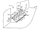
- FIG. 1 is an isometric schematic view of a flood guard embodiment of this invention showing a flood gate in retracted position.
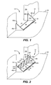
- FIG. 2 is the same view as FIG. 1 but showing a flood gate rising toward a closing position.
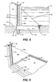
- FIG. 3 is a schematic sectional side view of a flood guard showing a flood gate resident in a flood guard housing installed in front of an opening.
- FIG. 4 is the same view as FIG. 3 schematically showing buoying rotation of the flood gate out of the gate housing.
- FIG. 5 is the same view as FIGS. 3 and 4 and schematically shows the flood gate rotated to a closed position by hydraulic force of accumulated water restrained behind the gate.
- FIG. 6 is a perspective view of a portion of an embodiment of this invention with the gate resident in the gate housing, the view being toward the front of the gate left obliquely from a position that would be inside an imagined opening the embodiment would protect.
- FIG. 7 is a perspective view of a portion of the embodiment of this invention variant slightly from that depicted in FIG. 6, with the gate rotated out of the gate housing, the view being toward the back of the gate obliquely from a position that would be outside an imagined opening the embodiment would protect, looking toward the imagined opening.
- FIG. 8 is a view of a left portion of the gate of the embodiment of FIG. 6 in rising position, the view being frontally toward the front of the gate from a position that would be inside and at a raised elevation (eye level) of an imagined opening the embodiment would protect.
- FIG. 9 is a perspective view of a gate of this invention installed guarding the entrance to an underground parking garage, with the gate lowered and resident in a gate housing.
- FIG. 10 is a perspective view of a gate of this invention installed guarding a passageway of an underground tunnel, with the gate lowered and resident in a gate housing.
- FIG. 11 is a perspective view from the same position as FIG. 10 showing the flood gate rising to guard the passage as it would under the force of waters flooding into the tunnel.
- reference numeral 10 designates a self actuating flood guard system 10 for refusing admission of rising surface water into a structural opening 12 of a construction 14 .
- the opening 12 has a bottom 16 and sides 18 a and 18 b .
- the system 10 comprises a buoyant gate 20 having a base 22 , sides 24 a and 24 b , top 26 , a front 28 , a back 29 and dimensions occlusive of at least a lower portion of opening 12 .
- Gate base 22 is arranged for location adjacent the bottom 16 opening 12 .
- gate 20 comprises a weight bearing flat structure over which pedestrian, automobile or other traffic may travel when passing through opening 12 under non flooding conditions.
- Gate 20 includes a flotation material and suitably comprises buoyant material providing a rigid upper surface for traffic, such as, referring to FIGS. 3 - 5 , a plurality of sealed structural aluminum tubes 30 a - 30 g , arranged side by side. As seen in FIGS. 2 - 5 , 7 and 11 , a plurality of support members 32 a - 32 f are transversely affixed to tubes 30 a - 30 g (about which, more below). For specific example, for a 12 foot wide garage entrance, the gate may be constructed of 12 feet lengths of 2 ⁇ 5 inch structural aluminum tubing 30 having a ⁇ fraction (1/8) ⁇ wall arranged and secured side by side to provide a flotation member 30 inches tall capable of bearing traffic.
- Support members 32 suitably would be 30 inches long on centers determined by the number of supports (e.g., 17 inch centers in the case of 14 supports for a 12 feet wide gate).
- the flotation material may comprise a honeycomb core structure sealingly arranged between two rigid panels, or a sealed gas bladder surmounted by a structural aluminum panel.
- a bonding material is used to attach the skin material to the honeycomb core.
- Such a honeycomb panel is used, for example, in the floor panels of most airliners and offers a high strength to weight material, and can be corrosion and fungi resistant.
- Honeycomb panels of this general type are manufactured, for example, by Hexcel Corporation, Stamford, Conn.; Plascore Inc., Zeeland, Mich.; M. C. Gill Corporation, El Monte, Calif.; and others.
- the panel suitably would be about 8 and ⁇ fraction (1/2) ⁇ feet wide and 2 inches thick with a honeycomb density suitably in the range of about 4-8 pounds per cubic foot (pcf) contained with a framework of 2 inch diameter, 0.125 inch wall thickness square tubing, and bonded to face skins of ⁇ fraction (3/16) ⁇ inch sheeting.
- the gate may comprise a sandwich in which the center is a crush proof buoyant closed cell foam polyurethane form or other satisfactory material within the skill of the art to employ.
- Pivotation members 33 comprising a hinge plate 34 ( 34 a , 34 b ) and pin 36 assembly (see FIGS. 3 - 6 ) hinge gate 20 at base 22 about a pivot axis co-incident with pin 36 that is parallel to bottom 16 of opening 12 .
- Pivotation members 34 , 36 allow gate 20 to rest or lay substantially parallel and adjacent grade, proximately in front of opening 12 (FIGS. 1, 3, 6 ), for pivotation upwardly (FIG. 4) toward and across opening 12 (FIGS. 2, 5, 7 ).
- a housing 38 for gate 20 and pivotation members 34 , 36 includes a floor 40 and sides 42 a , 42 b , and end 42 c apposite base 22 for containing gate 20 above floor 40 such that, with gate 20 resident in housing 38 , front 28 of gate 20 substantially closes or covers gate housing 38 (see FIGS. 1, 3, 6 ), suitably not covering a surface water portal into the housing in the form of a grate 44 giving surface water access to floor 40 of housing 38 when gate 20 is resident in housing 38 (FIG. 3).
- the portal may be located elsewhere with an inlet into a sidewall or the floor 40 of housing 38 , in which case, a substantial closing of the gate housing would extend to the end walls of housing 38 .
- Housing 38 and gate 20 are configured to permit surface water entering through portal 44 to rise beneath gate 20 and pivotingly buoy gate 20 upwardly from housing 38 for rotation about pin axis 36 toward opening 12 (FIGS. 2, 3).
- support members 32 a - 32 e project from the back 29 of gate 20 (FIG. 7), and serve both to support gate 20 above the floor pan 40 of housing 38 and to provide channels adjacent support members 32 a - 32 e through which water entering from portal 44 can flow under gate 20 .
- ribs of a height sufficient to span the separation of back 29 to floor 40 and support gate 20 horizontally above floor 40 may be constructed on floor pan 40 instead of members 32 a - 32 e being affixed to back 29 of gate 20 , and be spaced to provide access for water to run under back 29 of gate 20 .
- floor 40 may be deeper with flanges on opposing or all sides of the housing for support of a grate over floor 40 on which buoyant gate 20 may rest within housing 38 .
- Portal 44 is suitably located in housing 38 at the end or head of the housing remote from where base 22 of gate 20 is pivoted, i.e., near where top 26 of gate 20 resides when gate 20 lays in housing 38 , as shown.
- a pair of upright right triangular walls 48 a , 48 b reach from grade 46 and extend parallel alongside sides 24 a , 24 b of gate 20 at rest resident in housing 38 and hence alongside sides 39 a , 39 b of housing 38 .
- the altitude of the right triangular shaped walls 48 a , 48 b is adjacent opening 12 .
- Walls 48 a , 48 b have facing surfaces 49 a , 49 b .
- Surfaces 49 a , 49 b are spaced apart from one another sufficiently to allow gate 20 to pivot upwardly between walls 48 a , 48 b toward opening 12 .
- Jambs 50 a , 50 b adjacent sides 18 a , 18 b of opening 12 confront and stop rotation of gate 20 about axis 36 when gate 20 is rotated a predetermined extent under the closing force of hydrostatic pressure of rising water 52 (FIG. 5), putting gate 20 in a closed position that refuses admission of rising water to at least a lower portion of opening 12 .
- Jambs 50 a , 50 b suitably are L-shaped flanges fixed to walls 48 a , 48 b .
- the mentioned predetermined extent of upwardly permitted rotation suitably but not necessarily is an extent that places the jambs substantially upright but not in excess of 90 degrees relative to grade 46 .
- FIG. 6 and FIGS. 1 - 5 and 9 - 11 disclose a flood guard in which the jambs 50 a , 50 b are vertically arranged.
- FIG. 7 shows a variant of FIG. 6 in which jambs 50 a , 50 b (only 50 b is visible) are slightly less than vertical.
- a mechanism is advantageously provided as a safety factor to prevent unmanaged lowering of gate 20 , since, with a vertical disposition, there is no vertical gravitational vector acting on front 28 of gate 20 and gate 20 therefore is not predisposed to automatically lower as water recedes, as would a less than vertically disposed gate.
- a suitable safety mechanism is a latch 55 pivoting on pin 53 with a cam frontal surface 56 that slides over the top edge 29 of the rising gate 20 until the gate is pushed by rising water under notch 57 of the latch, whereupon the latch falls over the edge, fastening gate 20 to the vertical position.
- Seals 58 a , 58 b advantageously are affixed to sides 24 a , 24 b of gate 20 to sealingly close gaps between sides 24 a , 24 b and facing wall surfaces 49 a , 49 b during rotation of gate 20 toward opening 12 .
- seals 58 a , 58 b are contact seals that compress when brought into engagement with the surfaces 49 a , 49 b of walls 48 a , 48 b during rotation toward opening 12 .
- FIGS. 6 - 8 an embodiment of the gate system is shown on pertinent part.
- gate 20 is resident in housing 38 .
- FIG. 7 gate 20 is rising from housing 38 toward closure against jambs 50 a , 50 b .
- Seal 58 b (FIG. 8) is shown affixed to side 24 b under a retaining strip 54 b fastened to front 28 of gate 20 .
- Seal 58 b is compressed where the seal presses against wall 48 b .
- This provides a water tight barrier while rising water is driving gate 20 to the closing position fixed by jambs 50 a , 50 b .
- the flotation compartment comprising back 29 of gate 20 in the embodiment of FIGS. 6, 7 and 8 does not extend to the full height of the front 28 of gate 20 (although it may), in this instance providing a lip at the top 26 over which latch 55 may ride to secure gate 20 closed in the raised position after waters recede.
- jambs 50 a , 50 b are affixed to walls 48 a , 48 b adjacent opening 12 and reach upwardly from adjacent grade 46 .
- Jambs 50 a , 50 reach an elevation proximate the height of the upright walls 48 a , 48 b adjacent the opening. As seen in FIG. 6, the reach is substantially coincident with the height of wall 48 b at the location of wall 48 b to which jamb 50 b is affixed.
- Jambs 50 a , 50 b suitably include a resilient sealing surface 60 (see FIG. 6) arranged to cooperate with facing surfaces of the front of the gate in the closed position to seal against admission of water between jambs 50 a , 50 b and gate 20 .
- the facing surface is retaining strip 54 b (shown) and 54 a (not viewable).
- housing 38 suitably includes a outlet 61 leading to a drain tube 67 at an end of housing 20 opposite portal 40 .
- the outlet 61 and drain tube 67 allows removal of water from housing 38 when waters entering portal 40 other than in a flooding condition, as explained above.
- the flood guard system is an integral package or unit that can be installed by making a shallow excavation at the entrance to an opening of the construction to be protected and fixedly setting the unit in place.
- the unit can be used where the grade is horizontal, as shown, or is downwardly sloped.
- the walls 48 alternatively may extend from the construction 14 (FIGS. 1, 2).
- the walls 48 in cooperation with the jambs 50 and the gate 20 in its closed position are a barrage to water between walls 48 and construction 14 .
- the jambs 50 may be affixed to the construction 14 directly adjacent (including on) the sides 18 of the opening 12 . In that case, the jambs 50 in cooperation with the gate 20 in closed position are a barrage to water between the jambs 50 and the construction 14 .
- a flood guard of this invention is depicted installed in an opening 12 of an underground parking garage 14 approached by a downwardly sloped ramp 62 bulwarked at the sides from earth invasion by entrance wall structures 64 a , 64 b .
- Walls 48 a , 48 b abut immediately against the sides 18 a , 18 b of opening 12 .
- FIGS. 10 and 11 a flood guard of this invention is depicted installed in an opening of an underground pedestrian tunnel.
- the underground tunnel may be finished with attractive surfaces.
- Walls 48 a , 48 b minimally may have the right triangular shape such as depicted in FIGS. 1 - 9 for the reasons already stated, but may have any contour beyond the minimum of the hypotenuse of the triangle that is considered decorative.
- this is a rectangular shape, and suitably may be polished granite or other water impervious surface.
- the portion of the walls of the tunnel leading up to walls 48 a , 48 b are flush with walls 48 a , 48 b .
- jambs 50 a - 50 c suitably are faced with a resilient sealing material to resist leakage.
- the hydraulic pressure of water pressing against the resilient material is sufficient to forestall any significant leakage.
- a safety latch 55 is also suitably present (not shown in FIGS. 10 - 11 ).
- gate 20 In operation of the invention, referring to FIGS. 3 - 5 , gate 20 , of dimension occlusive to at least a lower portion of opening 12 and resident in recessed housing 38 adjacently in front of opening 12 , substantially parallel to grade 46 , admits surface water 52 into the housing recess through ports 44 (FIG. 3). Rise of water in the recess causes gate 20 to buoy upwardly from said recess pivoting on pivotation pin 36 in a rotation closing towards opening 12 (FIG. 4). Walls 48 wiped by compression seals 50 projecting from the sides 24 of gate 20 prevent rising surface water 52 from flowing around sides 24 of upwardly buoyed gate 20 between sides 24 and walls 48 . Rising surface water 52 accumulates behind gate 20 and hydraulic pressure of the water imparts a closing force rotating gate 20 toward, thence occlusively across, at least a lower portion of opening 12 (FIG. 5).
- a method that comprises (a) housing a buoyant gate 20 occlusive of least a lower portion of the opening 12 adjacently in front 16 of opening 12 , substantially parallel to grade 46 , in a recess 38 into which surface water 52 can flow, such that gate 20 housed in recess 38 provides a weigh bearing passageway on its front side 28 to opening 12 , (b) pivoting gate 20 about a pivot axis 36 parallel to the bottom 16 of opening 12 to allow gate 20 to pivot upwardly towards and across opening 12 from recess 38 , and (c) preventing rising surface water 52 from flowing around sides 24 a , 24 b of gate 20 , such that, on admission of surface water 54 into recess 38 , gate 20 pivotingly buoys upwardly from recess 38 in a rotation towards opening 12 , accumulating rising surface water 52 behind gate 20 , whereby hydraulic pressure exerts force rotation of gate 20 toward, thence occlusively across, at least a lower portion of opening 12 .
- opening 12 is intended to convey the meaning that gate 20 may be of dimension to close the entirety of an opening before which it is placed. Thus, the gate may entirely close the opening, as in FIGS. 10 - 11 .
Landscapes
- Engineering & Computer Science (AREA)
- General Engineering & Computer Science (AREA)
- Structural Engineering (AREA)
- Civil Engineering (AREA)
- Mechanical Engineering (AREA)
- Environmental & Geological Engineering (AREA)
- Ocean & Marine Engineering (AREA)
- Architecture (AREA)
- Special Wing (AREA)
- Barrages (AREA)
Abstract
Description
- This invention generally relates to method and apparatus for regulating the flow of water, more particularly, to water gates, and especially water gates in which the water gate turns about a pivot axis which is generally parallel to the horizon.
- Major flooding too often happens in urban areas when runoff of surface water from sustained and heavy rains, or stream overflow, or cresting or penetration of water retention dikes, overwhelms water drainage and removal systems. At high risk in any such situation are buildings with subterranean areas including basements, subterranean tunnels and halls, parking garages and the like. Surface water invading through open entries of the buildings runs to lower levels. As lower levels fill, flooding can climb to higher subterranean floors and to adjacent buildings if buildings are connected by underground pedestrian or utility tunnels. If standby power generators and/or fuel powered water evacuation pumps are located below surface grade, such as in a basement, as all too often is the case, the power generators and water pumps can be disabled by water flooding into an area where they are located, removing often the last line of flood defense of the building.
- Openings to buildings through which rising water can invade include entrances to covered receiving and loading docks, to underground parking areas and garages, to descending stairwells, and to vents, and potential entrances include grade-level and below grade windows or doors. Bottom-hinged “flip-up” flood gates, with inflatable gaskets, that are floor recessed when not in use, that have an exposed surface for traffic passage, and that are raised by hydraulic cylinders or winches, are commercially available. Other also not automatic building water barriers are shown in U.S. Pat. No. 5,943,832 for flood or storm resistant barriers for doorways or window opening; U.S. Pat. No. 5,283,979 for locking/opening system for watertight hatch, U.S. Pat. No. 4,582,451 for floodgate panel and sealing means therefor; and U.S. Pat. No. 4,355,000 for lightweight, removable gate seal.
- Storms that produce locally heavy flooding occur only sporadically, so available flood gates of the art as described above remain in a retracted position for long periods of time. Because these flood gates are not automatic, on-site or on-call personnel are required to put them into barrier position when a high water inundation event is anticipated. When the event is a cresting river or the like, there is some advance notice. Unfortunately, nature sometimes comes calling torrentially, unexpectedly and inconveniently, when personnel are not on site, such as the middle of the night, and even if on-call, the personnel may be prevented by flooding of roadways from getting to the site in time to erect the flood gates before the structure meant to be protected is already inundated.
- There have been efforts to automate erection of flood gates. One such example is U.S. Pat. No. 5,460,462, in which a vertically disposed flotation barrier elevates on guide tracks between channel posts when water rises within a vertical subterranean housing containing the flotation barrier. There are disadvantages, however, to such a vertical barrier. Hydrostatic forces generated by rising surface water press the barrier against its tracks, increasing friction and causing the barrier to resist the buoyancy forces working to raise the barrier vertically. Installation of the vertically disposed buoyant barrier requires evacuation of ground for the supporting structure to depth greater than the full height the barrier. Particularly in existing constructions such as parking garages and tunnels, the building structure itself or buried ancillary structure prevents excavations to a depth needed for placement of a vertical barrier. In addition, when a flood recedes, mud and flood debris from the water remain, and removal of debris from a tall, thin vertical slot in the ground, occluded with the flotation barrier, presents maintenance difficulties.
- U.S. Pat. No. 4,377,352, issued Mar. 22, 1983 to Goodstein, describes a self-actuating water containment barrier for guarding open fields along flooding streams or rising lakes. The barrier comprises a plurality of stanchions which are mounted for pivotal movement from a normal dormant horizontal position, to an active vertical position. The stanchions are interconnected with water barrier-forming sheeting to form a barrier which can conform to a particular land mass or shoreline. Float members are mounted on the bottom of the outer ends of the stanchions. At low water levels, the float members rest on a shallow body of water or on the ground in a near horizontal position. As the level of the water rises, the float members cause the adjacent stanchions to pivot into a vertical position, thereby raising the sheeting between them to form a water barrier. This water barrier float system is unsuitable for guarding openings to constructions where cars or human beings must normally pass over the apparatus involved during the long times when the apparatus is retracted at rest.
- This invention provides a flood guard method and apparatus for automatically refusing admission of rising surface water into a structural opening of a construction. By “construction” is meant any structure, building, erection, edifice or the like, and includes interior and exterior partitions and walls, in which openings such as doors or windows may occur, for passage from outside the construction to its interior, or within the construction from one room to another, or from one side of a partition to the other side, and this includes elongated passages such as tunnels and halls. The construction and the opening in the construction may be at ground level or below ground level, such as an underground parking garage, a basement, a subterranean tunnel or other subterranean space, so long as access to the construction or from one part of the construction to another is by an opening through which water can flow under the force of gravity. The essential factor is that the invention guards against flooding from surface water through an opening to the construction.
- In general, the invention involves (i) pivoting a buoyant and structurally rigid flood gate from adjacent grade about an axis at the base of the gate arranged adjacent the bottom of a construction opening generally parallel to grade, such that, on rise of surface water sufficient to float the gate, the gate is buoyed and by force of rising water is rotated about the pivot axis in the direction of the opening, and (ii) as the gate buoyantly rotates upwardly, preventing the rising water from flowing around the sides of the gate sufficiently that enough hydraulic pressure is impressed on the gate by the rising water to push the gate into closing contact with stops or jambs adjacent the sides of the opening, thereby closing the opening and barring admission of flood water into the construction. The combination of an initial buoyant rotation of the gate upwardly about a horizontal axis followed by hydraulic force from water accumulated against the back of the up-rotated gate completes closure of the opening (with closure maintained by impress of hydraulic pressure). With a buoyant flood gate reposed at grade, the buoyant action of the gate in response to rising surface water is a rotational closing force for less than half the closing movement, when hydraulic pressure forces from water accumulating on the water side of the gate take over and complete the closing movement. Gate buoyancy, dependant on a variety of factors, including amount and kind of buoyant material, weight, and height verses width of the gate, affects the relative degree to which buoyancy closing forces surrender primacy to hydrostatic closing forces in a particular design.
- Thus this invention provides a method for automatically refusing admission of rising surface water into a structural opening of a construction, the opening having opening-limiting margins, including a bottom, sides and usually a top. The method comprises (a) housing a buoyant gate of dimension occlusive to at least a lower portion of the opening adjacently in front of the opening, substantially parallel to grade, pivotingly arranged about a pivot axis parallel to the bottom of the opening and in a recess into which surface water can flow, (b) providing a portal for admitting surface water into the recess to cause the gate to pivotingly buoy upwardly from the recess in a rotation closing towards the opening, and (c) preventing rising surface water from flowing around sides of the upwardly buoyed gate, whereby rising surface water accumulates behind the gate and hydraulic pressure of the rising surface water exerts a continuing closing force rotating the gate toward, thence occlusively across, at least a lower portion of the opening.
- Apparatus is provided in accordance with the invention to perform the function of the invention. A self actuating flood guard for refusing admission of rising surface water into a structural opening of a construction, the opening having opening-limiting margins, including a bottom, sides and usually a top, comprises (1) a buoyant gate having a base, sides, a front, a back and dimensions occlusive of at least a lower portion of the opening, the base being arranged for location adjacent the bottom of the opening, (2) pivotation members hinging the gate at the base about a pivot axis parallel to the bottom of the opening and allowing the gate to rest substantially parallel and adjacent grade proximately in front of the opening for pivotation upwardly toward and transversely to the opening, (3) a pair of upright walls reaching from grade and extending alongside the sides of the gate at rest, the walls having facing surfaces spaced apart sufficiently to allow the gate to pivot upwardly between them toward the opening with the sides of the gate close enough to the facing wall surfaces to permit hydrostatic pressure of surface water rising from the grade to develop against the back of the gate effective to impart a closing force on the gate after the gate buoyantly has pivoted from rest upwardly about the axis, and (4) jambs adjacent the sides of the opening for confronting and stopping rotation of the gate about the axis when the gate is rotated a predetermined extent under the closing force of the rising water hydrostatic pressure, thereby putting the gate in a closed position refusing admission of rising water into at least a lower portion of the opening. The predetermined extent suitably but not necessarily is an extent that places the jambs substantially upright but not in excess of 90 degrees relative to the grade.
- The flood guard advantageously comprises a housing for the gate and pivotation members, the housing including a floor and sides for containing the gate above the floor such that with the gate resident in the housing the front of the gate substantially closes the gate housing. In many applications the gate is weight bearing, and when resident in the housing, it provides a passageway for traffic into the construction through the opening.
- The gate housing further comprises a surface water portal into the housing giving access to the floor of the housing when the gate is resident in the housing, the housing and gate being configured to permit surface water entering through the portal to rise beneath the gate and pivotingly buoy the gate upwardly from the housing for rotation about the axis toward the opening. Optionally the portal is located in the housing at least adjacent the location in the housing remote from where the base of the gate is pivoted.
- A drain is provided in the gate housing to remove waters flowing into the housing. Typically the removed water is emptied to a storm water collector tributary such as storm sewer, ditch, canal or other water collecting and removal system, including return to streets to discharge from the street to ditches or to storm sewers accessed by inlets along the sides of the streets. The purpose of the drain is to prevent the gate from floating up and out of its housing on the occasion of a heavy downpour which has not become a flooding situation. So long as the storm sewer or other water collector system is not full, water will not back up in the drain but will flow out and be removed by the water collector system. But in a condition where storm sewers are full and flowing at maximum rate, a limiting condition has been reached; street water no is longer accepted in the storm sewer, piles up, spreads and rises. This is the situation where the gate self-actuates, because the gate housing drain can no longer discharge its received water, and water entering the housing portal rises, elevating the gate. Thus the gate does not elevate during a mere heavy downpour but only when there is rising surface water in a flooding condition.
- Seals affixed to the sides of the gate sealingly closing the gaps between the sides of the gate and the facing wall surfaces during rotation of the gate toward the opening of the construction. Suitably the seals are contact seals, preferably of a type that compress when brought into engagement with the walls during rotation toward the opening.
- In one embodiment the jambs are affixed to the upright walls adjacent the opening and reach upwardly from adjacent grade. The jambs may reach an elevation proximate the height of the upright walls adjacent the opening, and may and preferably do include a resilient sealing surface arranged to cooperate with facing surfaces of the front of the gate in the closed position to seal against admission of water between the jamb and the gate.
- The gate comprises buoyant material, for example, it may comprise a plurality of sealed tubes arranged side by side, or a honeycomb core structure sealingly arranged between two rigid panels. Alternatively the gate may have a bladder for a flotation material.
- While the rotation of the gate about a pivot axis parallel to the bottom of the opening to be protected describes an arc, the rise of surface water is planar to horizontal, so more than a right angular shape of the upright walls between which the gate rotates upwardly is surplus structure, although structure may be provided above the hypotenuse to the right angle triangle for appearance or architecturally pleasing reasons. The walls are, of course, water impervious.
- The jambs may be affixed to the construction on the sides of the opening. Alternatively the jambs may be freestanding from grade level or may project toward the opening from the upright walls, but the jambs are always spaced apart not more than the spacing of facing surfaces of the walls. Where the jambs are freestanding, the jambs are arranged with respect to the construction to act as a barrage to water between the jambs and the construction. Where the jambs are part of the walls, the walls are arranged relative to the construction to form a barrage to water between the walls and the construction. In an application of the invention, the upright walls extend from the construction and in cooperation with the jambs and the gate in the closed position provide a barrage to water between the walls and the construction.
- The invention works either where the grade on which it is installed is horizontal or is angled relative to horizontal, either declined or inclined. Thus the construction may be a parking garage with underground parking accessed by a downwardly sloped ramp in which the flood guard may be installed.
- The system of the invention is completely passive and automatic. There is no power or maintenance requirement and the gate normally rests out of the way so that once it is installed, most people passing or driving over it don't even realize it is there. The method and apparatus of this invention have advantages over a vertical rising gate such as disclosed in U.S. Pat. No. 5,460,462, described above. For one thing, hydrostatic pressure of the rising water works to the advantage of the flood gate system of this invention, rather than against it. As mentioned, in the buoyant vertically rising barrier, any forces generated by dammed water to one side of the barrier serve to press the barrier against its tracks, increasing friction and making the barrier more resistant to floating upwards to full elevation. In the instant invention, the water pressure actually pushes the gate into fully elevated position. The gate will fully close when the water reaches between about one-third to about one-half, e.g., about 35-45%, of the overall height of a normally horizontally retracted gate.
- Further, installation of the barrier is vastly simplified due to its horizontal packaging. The buoyant gate and its housing can be as little as only about four inches in height, whereas a buoyant vertically rising barrier must be the installed to a depth equal to the full height of the barrier plus some additions for structural support. Installation in roadways, and particularly in parking garages or tunnel systems, where other structures may lie closely beneath, is made possible by the present invention due to the minimized need to excavate material. Actually the design of this invention can be installed without any digging at all where necessary; it can be installed on top of the approach surface to the construction opening and would look like a flat speed bump lying on the surface of the pavement.
- Also, maintenance of the flood gate of the instant invention is greatly eased due to its horizontal nature. In the case of a flood, mud, debris, and other detritus is carried in the water. When the flood recedes, much of this material will fall out of the water and remain behind. Cleaning the flood gate of the instant invention will require the washing of a broad, flat pan compared to cleaning a tall, thin slot in the ground.
- These and other advantages of the instant invention will become more apparent to those in the art from the description of an embodiment which follows after an identification of the drawings used in connection with the description.
- FIG. 1 is an isometric schematic view of a flood guard embodiment of this invention showing a flood gate in retracted position.
- FIG. 2 is the same view as FIG. 1 but showing a flood gate rising toward a closing position.
- FIG. 3 is a schematic sectional side view of a flood guard showing a flood gate resident in a flood guard housing installed in front of an opening.
- FIG. 4 is the same view as FIG. 3 schematically showing buoying rotation of the flood gate out of the gate housing.
- FIG. 5 is the same view as FIGS. 3 and 4 and schematically shows the flood gate rotated to a closed position by hydraulic force of accumulated water restrained behind the gate.
- FIG. 6 is a perspective view of a portion of an embodiment of this invention with the gate resident in the gate housing, the view being toward the front of the gate left obliquely from a position that would be inside an imagined opening the embodiment would protect.
- FIG. 7 is a perspective view of a portion of the embodiment of this invention variant slightly from that depicted in FIG. 6, with the gate rotated out of the gate housing, the view being toward the back of the gate obliquely from a position that would be outside an imagined opening the embodiment would protect, looking toward the imagined opening.
- FIG. 8 is a view of a left portion of the gate of the embodiment of FIG. 6 in rising position, the view being frontally toward the front of the gate from a position that would be inside and at a raised elevation (eye level) of an imagined opening the embodiment would protect.
- FIG. 9 is a perspective view of a gate of this invention installed guarding the entrance to an underground parking garage, with the gate lowered and resident in a gate housing.
- FIG. 10 is a perspective view of a gate of this invention installed guarding a passageway of an underground tunnel, with the gate lowered and resident in a gate housing.
- FIG. 11 is a perspective view from the same position as FIG. 10 showing the flood gate rising to guard the passage as it would under the force of waters flooding into the tunnel.
- Referring to the drawings,
reference numeral 10 designates a self actuatingflood guard system 10 for refusing admission of rising surface water into astructural opening 12 of aconstruction 14. Theopening 12 has a bottom 16 andsides system 10 comprises abuoyant gate 20 having a base 22, sides 24 a and 24 b, top 26, a front 28, a back 29 and dimensions occlusive of at least a lower portion ofopening 12.Gate base 22 is arranged for location adjacent the bottom 16opening 12. As shown in FIGS. 1 and 2,gate 20 comprises a weight bearing flat structure over which pedestrian, automobile or other traffic may travel when passing throughopening 12 under non flooding conditions. -
Gate 20 includes a flotation material and suitably comprises buoyant material providing a rigid upper surface for traffic, such as, referring to FIGS. 3-5, a plurality of sealed structural aluminum tubes 30 a-30 g, arranged side by side. As seen in FIGS. 2-5, 7 and 11, a plurality of support members 32 a-32 f are transversely affixed to tubes 30 a-30 g (about which, more below). For specific example, for a 12 foot wide garage entrance, the gate may be constructed of 12 feet lengths of 2×5 inch structural aluminum tubing 30 having a {fraction (1/8)} wall arranged and secured side by side to provide a flotation member 30 inches tall capable of bearing traffic. Support members 32 suitably would be 30 inches long on centers determined by the number of supports (e.g., 17 inch centers in the case of 14 supports for a 12 feet wide gate). Alternatively the flotation material may comprise a honeycomb core structure sealingly arranged between two rigid panels, or a sealed gas bladder surmounted by a structural aluminum panel. In the case of a composite structure of a honeycomb core material sandwiched vertically between horizontal skins of aluminum or other high strength composite material, a bonding material is used to attach the skin material to the honeycomb core. Such a honeycomb panel is used, for example, in the floor panels of most airliners and offers a high strength to weight material, and can be corrosion and fungi resistant. Honeycomb panels of this general type are manufactured, for example, by Hexcel Corporation, Stamford, Conn.; Plascore Inc., Zeeland, Mich.; M. C. Gill Corporation, El Monte, Calif.; and others. For an eight feet wide entrance to a parking garage, the panel suitably would be about 8 and {fraction (1/2)} feet wide and 2 inches thick with a honeycomb density suitably in the range of about 4-8 pounds per cubic foot (pcf) contained with a framework of 2 inch diameter, 0.125 inch wall thickness square tubing, and bonded to face skins of {fraction (3/16)} inch sheeting. Alternatively, the gate may comprise a sandwich in which the center is a crush proof buoyant closed cell foam polyurethane form or other satisfactory material within the skill of the art to employ. -
Pivotation members 33 comprising a hinge plate 34 (34 a, 34 b) andpin 36 assembly (see FIGS. 3-6)hinge gate 20 atbase 22 about a pivot axis co-incident withpin 36 that is parallel to bottom 16 ofopening 12.Pivotation members 34, 36 allowgate 20 to rest or lay substantially parallel and adjacent grade, proximately in front of opening 12 (FIGS. 1, 3, 6), for pivotation upwardly (FIG. 4) toward and across opening 12 (FIGS. 2, 5, 7). - A
housing 38 forgate 20 andpivotation members 34, 36 includes afloor 40 andsides apposite base 22 for containinggate 20 abovefloor 40 such that, withgate 20 resident inhousing 38,front 28 ofgate 20 substantially closes or covers gate housing 38 (see FIGS. 1, 3, 6), suitably not covering a surface water portal into the housing in the form of agrate 44 giving surface water access tofloor 40 ofhousing 38 whengate 20 is resident in housing 38 (FIG. 3). The portal may be located elsewhere with an inlet into a sidewall or thefloor 40 ofhousing 38, in which case, a substantial closing of the gate housing would extend to the end walls ofhousing 38.Housing 38 andgate 20 are configured to permit surface water entering throughportal 44 to rise beneathgate 20 andpivotingly buoy gate 20 upwardly fromhousing 38 for rotation aboutpin axis 36 toward opening 12 (FIGS. 2, 3). In the embodiment, support members 32 a-32 e project from the back 29 of gate 20 (FIG. 7), and serve both to supportgate 20 above thefloor pan 40 ofhousing 38 and to provide channels adjacent support members 32 a-32 e through which water entering from portal 44 can flow undergate 20. Alternatively, ribs of a height sufficient to span the separation of back 29 tofloor 40 andsupport gate 20 horizontally abovefloor 40 may be constructed onfloor pan 40 instead of members 32 a-32 e being affixed to back 29 ofgate 20, and be spaced to provide access for water to run under back 29 ofgate 20. Orfloor 40 may be deeper with flanges on opposing or all sides of the housing for support of a grate overfloor 40 on whichbuoyant gate 20 may rest withinhousing 38. Other configurations will be apparent to those skilled in the art based on the concepts disclosed herein.Portal 44 is suitably located inhousing 38 at the end or head of the housing remote from wherebase 22 ofgate 20 is pivoted, i.e., near where top 26 ofgate 20 resides whengate 20 lays inhousing 38, as shown. - A pair of upright right
triangular walls grade 46 and extend parallel alongside sides 24 a, 24 b ofgate 20 at rest resident inhousing 38 and hence alongside sides 39 a, 39 b ofhousing 38. The altitude of the right triangular shapedwalls adjacent opening 12.Walls surfaces Surfaces gate 20 to pivot upwardly betweenwalls opening 12.Sides gate 20 are close enough to respective facing wall surfaces 49 a, 49 b to permit hydrostatic pressure of surface water 48 rising fromgrade 46 to develop against back 29 ofgate 20 effective to impart a closing force (FIG. 4) ongate 20 aftergate 20 buoyantly has pivoted from residence (FIG. 3) upwardly aboutpin axis 36. - Jambs 50 a, 50 b
adjacent sides gate 20 aboutaxis 36 whengate 20 is rotated a predetermined extent under the closing force of hydrostatic pressure of rising water 52 (FIG. 5), puttinggate 20 in a closed position that refuses admission of rising water to at least a lower portion ofopening 12. Jambs 50 a, 50 b suitably are L-shaped flanges fixed towalls grade 46. If the jambs are less than vertical to ahorizontal grade 46, and if no mechanism is provided to holdgate 20 raised, then, as flood waters recede,gate 20 will automatically lower itself. A vertical disposition is preferred for the simple reason that it provides a little more height against rising water. FIG. 6 and FIGS. 1-5 and 9-11 disclose a flood guard in which thejambs gate 20, since, with a vertical disposition, there is no vertical gravitational vector acting onfront 28 ofgate 20 andgate 20 therefore is not predisposed to automatically lower as water recedes, as would a less than vertically disposed gate. A suitable safety mechanism is alatch 55 pivoting onpin 53 with a camfrontal surface 56 that slides over thetop edge 29 of the risinggate 20 until the gate is pushed by rising water undernotch 57 of the latch, whereupon the latch falls over the edge, fasteninggate 20 to the vertical position. - Seals 58 a, 58 b advantageously are affixed to
sides gate 20 to sealingly close gaps betweensides gate 20 towardopening 12. Suitably seals 58 a, 58 b are contact seals that compress when brought into engagement with thesurfaces walls opening 12. - Referring particularly to FIGS. 6-8, an embodiment of the gate system is shown on pertinent part. In FIG. 6,
gate 20 is resident inhousing 38. In FIG. 7,gate 20 is rising fromhousing 38 toward closure againstjambs side 24 b under a retainingstrip 54 b fastened tofront 28 ofgate 20. Seal 58 b is compressed where the seal presses againstwall 48 b. This provides a water tight barrier while rising water is drivinggate 20 to the closing position fixed byjambs gate 20 in the embodiment of FIGS. 6, 7 and 8 does not extend to the full height of thefront 28 of gate 20 (although it may), in this instance providing a lip at the top 26 over which latch 55 may ride to securegate 20 closed in the raised position after waters recede. - In the embodiment of FIGS. 1-11,
jambs walls adjacent opening 12 and reach upwardly fromadjacent grade 46. Jambs 50 a, 50 reach an elevation proximate the height of theupright walls wall 48 b at the location ofwall 48 b to which jamb 50 b is affixed. - Jambs 50 a, 50 b suitably include a resilient sealing surface 60 (see FIG. 6) arranged to cooperate with facing surfaces of the front of the gate in the closed position to seal against admission of water between
jambs gate 20. In the embodiment of FIGS. 6-8, the facing surface is retainingstrip 54 b (shown) and 54 a (not viewable). - As seen in the embodiment of FIGS. 3-6 and 7,
housing 38 suitably includes aoutlet 61 leading to adrain tube 67 at an end ofhousing 20 oppositeportal 40. Theoutlet 61 anddrain tube 67 allows removal of water fromhousing 38 whenwaters entering portal 40 other than in a flooding condition, as explained above. - In the embodiment of FIGS. 6-8, the flood guard system is an integral package or unit that can be installed by making a shallow excavation at the entrance to an opening of the construction to be protected and fixedly setting the unit in place. The unit can be used where the grade is horizontal, as shown, or is downwardly sloped.
- In accordance with the invention, the walls 48 alternatively may extend from the construction 14 (FIGS. 1, 2). In such configuration, the walls 48 in cooperation with the jambs 50 and the
gate 20 in its closed position (FIG. 2) are a barrage to water between walls 48 andconstruction 14. Alternatively also, the jambs 50 may be affixed to theconstruction 14 directly adjacent (including on) the sides 18 of theopening 12. In that case, the jambs 50 in cooperation with thegate 20 in closed position are a barrage to water between the jambs 50 and theconstruction 14. - Referring to FIG. 9, a flood guard of this invention is depicted installed in an
opening 12 of anunderground parking garage 14 approached by a downwardly slopedramp 62 bulwarked at the sides from earth invasion byentrance wall structures Walls sides opening 12. - Referring to FIGS. 10 and 11, a flood guard of this invention is depicted installed in an opening of an underground pedestrian tunnel. The underground tunnel may be finished with attractive surfaces.
Walls walls walls lateral jambs opening 12, and as in embodiments 1-9, jambs 50 a-50 c suitably are faced with a resilient sealing material to resist leakage. The hydraulic pressure of water pressing against the resilient material is sufficient to forestall any significant leakage. Asafety latch 55 is also suitably present (not shown in FIGS. 10-11). - In operation of the invention, referring to FIGS. 3-5,
gate 20, of dimension occlusive to at least a lower portion ofopening 12 and resident in recessedhousing 38 adjacently in front of opening 12, substantially parallel tograde 46, admitssurface water 52 into the housing recess through ports 44 (FIG. 3). Rise of water in the recess causesgate 20 to buoy upwardly from said recess pivoting onpivotation pin 36 in a rotation closing towards opening 12 (FIG. 4). Walls 48 wiped by compression seals 50 projecting from the sides 24 ofgate 20 prevent risingsurface water 52 from flowing around sides 24 of upwardly buoyedgate 20 between sides 24 and walls 48. Risingsurface water 52 accumulates behindgate 20 and hydraulic pressure of the water imparts a closingforce rotating gate 20 toward, thence occlusively across, at least a lower portion of opening 12 (FIG. 5). - There is thus provided a method that comprises (a) housing a
buoyant gate 20 occlusive of least a lower portion of theopening 12 adjacently infront 16 ofopening 12, substantially parallel tograde 46, in arecess 38 into whichsurface water 52 can flow, such thatgate 20 housed inrecess 38 provides a weigh bearing passageway on itsfront side 28 to opening 12, (b) pivotinggate 20 about apivot axis 36 parallel to the bottom 16 of opening 12 to allowgate 20 to pivot upwardly towards and across opening 12 fromrecess 38, and (c) preventing risingsurface water 52 from flowing around sides 24 a, 24 b ofgate 20, such that, on admission of surface water 54 intorecess 38,gate 20 pivotingly buoys upwardly fromrecess 38 in a rotation towards opening 12, accumulating risingsurface water 52 behindgate 20, whereby hydraulic pressure exerts force rotation ofgate 20 toward, thence occlusively across, at least a lower portion ofopening 12. - The phrase “at least a lower portion” of opening 12 is intended to convey the meaning that
gate 20 may be of dimension to close the entirety of an opening before which it is placed. Thus, the gate may entirely close the opening, as in FIGS. 10-11. - Having described the invention both generally, schematically and in connection with a preferred embodiment, those skilled in the art will perceive variations of the invention which although not the same as those described herein will be within the scope and spirit of the claims, which now follow.
Claims (38)
Priority Applications (1)
| Application Number | Priority Date | Filing Date | Title |
|---|---|---|---|
| US10/116,249 US6623209B1 (en) | 2002-04-04 | 2002-04-04 | Automatic flood gate |
Applications Claiming Priority (1)
| Application Number | Priority Date | Filing Date | Title |
|---|---|---|---|
| US10/116,249 US6623209B1 (en) | 2002-04-04 | 2002-04-04 | Automatic flood gate |
Publications (2)
| Publication Number | Publication Date |
|---|---|
| US6623209B1 US6623209B1 (en) | 2003-09-23 |
| US20030190193A1 true US20030190193A1 (en) | 2003-10-09 |
Family
ID=28041080
Family Applications (1)
| Application Number | Title | Priority Date | Filing Date |
|---|---|---|---|
| US10/116,249 Expired - Lifetime US6623209B1 (en) | 2002-04-04 | 2002-04-04 | Automatic flood gate |
Country Status (1)
| Country | Link |
|---|---|
| US (1) | US6623209B1 (en) |
Cited By (36)
| Publication number | Priority date | Publication date | Assignee | Title |
|---|---|---|---|---|
| US20030143027A1 (en) * | 2001-07-09 | 2003-07-31 | Henry K. Obermeyer | Water control gate and actuator therefore |
| US20040096275A1 (en) * | 2001-03-16 | 2004-05-20 | Rorheim Thor Olav | Portable flood barrier section and flood barrier |
| US20050002737A1 (en) * | 2001-11-13 | 2005-01-06 | Martin Cullen | Watertight gate mechanism |
| US7364385B1 (en) | 2006-09-11 | 2008-04-29 | George Michael Luke | Protective flood barrier |
| US20090220301A1 (en) * | 2006-07-26 | 2009-09-03 | Spacetech.Co., Ltd. | Tide apparatus and tide structure |
| US20090252557A1 (en) * | 2008-04-02 | 2009-10-08 | Wayne Fisher | Flood barrier system |
| US7810285B1 (en) * | 2006-09-15 | 2010-10-12 | Liptak Robert L | Building barrier system and associated method |
| GB2470749A (en) * | 2009-06-04 | 2010-12-08 | John Charles Macintosh Forrest | Flood defence apparatus |
| US20120163916A1 (en) * | 2010-12-27 | 2012-06-28 | Waters Jr Louis A | Self-actuating storm surge barrier |
| GB2491011A (en) * | 2011-05-18 | 2012-11-21 | Charles Stuart Brindley | A Self-raising Flood Protection Barrier |
| JP2013002250A (en) * | 2011-06-21 | 2013-01-07 | Hitachi Zosen Corp | Floating body type flap gate |
| JP2013534282A (en) * | 2010-08-05 | 2013-09-02 | フロッドブレイク,エルエルシー | Self-acting flood guard |
| KR20140075694A (en) * | 2011-10-19 | 2014-06-19 | 히다치 조센 가부시키가이샤 | Flap gate-type waterproof panel for wall placement |
| EP2257691A4 (en) * | 2008-01-18 | 2015-08-26 | Floodbreak L L C | AUTOMATIC FLOOD PROTECTION FOR UNDERGROUND VENTILATION PIPES |
| ES2551282A1 (en) * | 2014-05-15 | 2015-11-17 | Iván VICENTE SÁNCHEZ | Sealing system for holes and doors of buildings that prevents or minimizes the effects of floods (Machine-translation by Google Translate, not legally binding) |
| JP2015209714A (en) * | 2014-04-28 | 2015-11-24 | 日立造船株式会社 | Floating flap gate |
| CN105672212A (en) * | 2014-10-15 | 2016-06-15 | 曾立宇 | Electric power free lifting type flood gate |
| JP2016142030A (en) * | 2015-02-02 | 2016-08-08 | 株式会社宇根鉄工所 | Buoyant waterproof device |
| WO2017077396A1 (en) * | 2015-11-04 | 2017-05-11 | Waters Louis A Jr | Self-actuating flood guard |
| WO2017133680A1 (en) * | 2016-02-04 | 2017-08-10 | 南京军理科技股份有限公司 | Automatic water barrier device |
| WO2017147349A1 (en) * | 2016-02-23 | 2017-08-31 | Obermeyer Henry K | Water control gate |
| JP2018013033A (en) * | 2017-10-26 | 2018-01-25 | 日立造船株式会社 | Floating body type flap gate |
| JP2018053610A (en) * | 2016-09-30 | 2018-04-05 | 日立造船株式会社 | Bearing of flap gate and flap gate |
| IT201600131737A1 (en) * | 2016-12-28 | 2018-06-28 | Giuseppe Giannini | Floating barrier with multiple stackable panels and mounting method |
| JP2019065615A (en) * | 2017-10-03 | 2019-04-25 | 日立造船株式会社 | Floating body type lifting gate and installation method of the same |
| JP2020016026A (en) * | 2018-07-23 | 2020-01-30 | 株式会社デプロ | Waterproof device |
| AT522249A1 (en) * | 2019-03-12 | 2020-09-15 | Amari Austria Gmbh | Device for retaining a fluid |
| US10975539B2 (en) * | 2019-06-26 | 2021-04-13 | Robert John Parsons | Rapidly deployable flood defence system |
| CN113216096A (en) * | 2021-05-06 | 2021-08-06 | 中国葛洲坝集团第一工程有限公司 | Jacking-free gate bottom pivot sealing element and in-situ maintenance method |
| US11306530B1 (en) * | 2020-09-24 | 2022-04-19 | Karl Krause | Garage floor barricade and associated methods |
| IT202000026410A1 (en) | 2020-11-05 | 2022-05-05 | Daniele GONELLI | MOBILE BULKHEAD, USABLE AS A BARRIER FOR THE PROTECTION OF THRESHOLDS FROM FLOODING DUE TO FLOODS AND SIMILAR |
| US20220162821A1 (en) * | 2020-11-20 | 2022-05-26 | Flood Control International Ltd | Flood defence |
| US20230021317A1 (en) * | 2019-10-15 | 2023-01-26 | Rubicon Research Pty Ltd | Overshot and undershot control gate |
| JP2023148705A (en) * | 2022-03-30 | 2023-10-13 | 豊国工業株式会社 | Water stop device |
| KR20240161260A (en) * | 2023-05-04 | 2024-11-12 | 주식회사하나엔지니어링 | Flood defense wall for the pile foundation |
| KR20250042623A (en) * | 2023-09-20 | 2025-03-27 | 서석주 | Water shield for underground entrances |
Families Citing this family (75)
| Publication number | Priority date | Publication date | Assignee | Title |
|---|---|---|---|---|
| GB0108609D0 (en) * | 2001-04-05 | 2001-05-23 | Shapero Robin W | Improvements rlating to limiting flood damage |
| GB0112468D0 (en) * | 2001-05-23 | 2001-07-11 | Abbott Steven | A flood water barrier |
| US7037031B2 (en) * | 2003-02-03 | 2006-05-02 | Haynie Mark D | Automatic barricade for low water crossings |
| US20040184880A1 (en) * | 2003-02-03 | 2004-09-23 | Haynie Mark D. | Automatic barricade for low water crossings |
| US7951291B2 (en) * | 2003-03-06 | 2011-05-31 | Khalil Ibrahim Nino | Automatic fluid channel screen lock-unlock system |
| GB0404954D0 (en) * | 2004-03-04 | 2004-04-07 | Forrest John C M | An aparatus and method for flood defence |
| DE102005013462A1 (en) * | 2005-03-21 | 2006-09-28 | Anhamm, Helmut | Room close off device e.g. for partitioning area against flowing fluid such as water, has flap which is tiltable around axis from first position into second position and driver provided for moving flap around axis |
| DE102005055017A1 (en) * | 2005-11-18 | 2007-05-24 | Anhamm, Helmut | A hinged partition and a device for partitioning a space against a fluid flowing into or out of the room |
| US7467911B2 (en) * | 2006-01-20 | 2008-12-23 | Flury Ronald J | Storm drain basin gate system |
| US7270498B1 (en) * | 2006-06-09 | 2007-09-18 | Andrew Albanese | Flood vent |
| US7726907B2 (en) | 2006-08-10 | 2010-06-01 | Mccreedy C Thomas | Automatic trip gate |
| US7497644B1 (en) * | 2007-05-31 | 2009-03-03 | Maurice Cohen | Automatic liquid barrier system |
| US20090060649A1 (en) * | 2007-08-27 | 2009-03-05 | Neff John D | Flood-actuated roadblock barrier gate |
| US8277645B2 (en) * | 2008-12-17 | 2012-10-02 | Jarvis Jr Ernest | Automatic retractable screen system for storm drain inlets |
| JP5166311B2 (en) * | 2009-02-04 | 2013-03-21 | 日本工営株式会社 | Switchgear |
| JP5166309B2 (en) * | 2009-02-04 | 2013-03-21 | 日本工営株式会社 | Switchgear |
| US20100199578A1 (en) * | 2009-02-12 | 2010-08-12 | Checketts Stanley J | Home saver storm shield |
| JP5180945B2 (en) * | 2009-11-24 | 2013-04-10 | 日立造船株式会社 | Mooring device for undulating gate breakwater |
| US8246272B1 (en) * | 2010-01-19 | 2012-08-21 | Denios, Inc. | Actuated spill barrier |
| JP5329452B2 (en) * | 2010-01-27 | 2013-10-30 | 日立造船株式会社 | Floating gate flap gate |
| US8616621B2 (en) | 2010-08-03 | 2013-12-31 | Harper Engineering Co. | Potted panel latch system |
| EP2625341B8 (en) | 2010-10-04 | 2020-10-07 | Parafoil Design & Engineering Pte Ltd | A floodgate |
| GB2486245B (en) * | 2010-12-09 | 2016-08-03 | Thomas Evans Geoffery | A flood barrier |
| US20120163917A1 (en) * | 2010-12-27 | 2012-06-28 | Waters Jr Louis A | Super elevation surface self-actuating flood barrier |
| FR2971322B1 (en) * | 2011-02-03 | 2014-05-02 | Saipem Sa | FLEXIBLE SUBMARINE LINE BEND LIMITER AND BACKFILL BOND INSTALLATION COMPRISING THE SAME |
| US8939677B2 (en) * | 2011-05-04 | 2015-01-27 | Hydro Green Energy, Llc | Moveable element and power generation system for low head facilities |
| JP5810695B2 (en) * | 2011-07-12 | 2015-11-11 | 豊和工業株式会社 | Waterproof door sealing mechanism and waterproof door device |
| MY152334A (en) * | 2011-12-28 | 2014-09-15 | Johnson & Nicholson M Sdn Bhd | Flood control device |
| JP6305940B2 (en) | 2012-02-08 | 2018-04-04 | ウォーターズ,ルイス,エー,ジュニア | Self-operating flood waterproof wall |
| US20120148346A1 (en) * | 2012-03-01 | 2012-06-14 | Shahriar Eftekharzadeh | Self-deploying floodwall |
| RO127672B1 (en) * | 2012-03-15 | 2016-04-29 | Petre Popa | Hydrotechnical-architectural system for protecting shores against waves |
| US9004814B2 (en) | 2013-02-25 | 2015-04-14 | New York City Transit Authority | Passive underground flood protection |
| US9458588B2 (en) | 2013-03-15 | 2016-10-04 | Floodbreak, Llc | Flood guard barrier lifting system |
| JP6055707B2 (en) * | 2013-03-29 | 2016-12-27 | 日立造船株式会社 | Pipe stop device |
| WO2014183070A1 (en) | 2013-05-09 | 2014-11-13 | Waters Louis A | Self-actuating flood quard |
| US20150012006A1 (en) * | 2013-07-02 | 2015-01-08 | Cardica, Inc. | Anastomosis stapling/clipping devices, systems and methods |
| US10435909B2 (en) | 2013-10-06 | 2019-10-08 | Floodbreak, L.L.C. | Flood protection for underground air vents |
| US10435907B2 (en) | 2013-10-06 | 2019-10-08 | Floodbreak, L.L.C. | Flood protection for underground air vents |
| US10435908B2 (en) | 2013-10-06 | 2019-10-08 | Floodbreak, L.L.C. | Flood protection for underground air vents |
| US10435910B2 (en) | 2013-10-06 | 2019-10-08 | Floodbreak, L.L.C. | Flood protection for underground air vents |
| US10435906B2 (en) | 2013-10-06 | 2019-10-08 | Floodbreak, L.L.C. | Flood protection for underground air vents |
| US9567778B2 (en) | 2013-10-16 | 2017-02-14 | Harper Engineering Company | Methods for installation of potted inserts having a latch mechanism |
| US9303448B2 (en) * | 2013-10-23 | 2016-04-05 | Zachary Dax Olkin | Flood shield systems and methods |
| CN103498450B (en) * | 2013-10-23 | 2015-08-05 | 张卫 | Automatic prevention waterlogging gate |
| GB2514879B (en) * | 2014-03-06 | 2015-05-06 | Antonios Toumazis | Self-operated barrier for flood, spill and other protection |
| JP6227477B2 (en) * | 2014-05-16 | 2017-11-08 | 日立造船株式会社 | Pipe stop device |
| US10036133B2 (en) | 2015-02-12 | 2018-07-31 | Rsa Protective Technologies, Llc | Method and system for a rising floodwall system |
| CN104762933B (en) * | 2015-04-28 | 2016-06-08 | 山东农业大学 | Automatic measuring water intake hollow gate |
| EP3339513B1 (en) * | 2015-09-25 | 2020-03-25 | Terata, Hiroshi | Sluice gate |
| CN105484176A (en) * | 2015-12-25 | 2016-04-13 | 陈明 | Deceleration strip doubling as flood-control blocking dam |
| CN106400741B (en) * | 2016-11-14 | 2017-10-13 | 南京军理科技股份有限公司 | A kind of baffle device for water |
| JP6118958B1 (en) * | 2016-06-06 | 2017-04-26 | 英外 ▲濱▼田 | Improved movable tsunami buffer facility |
| US10975538B2 (en) | 2016-06-13 | 2021-04-13 | Rsa Protective Technologies, Llc | Method and system for a retractable floodwall system |
| MX2018015520A (en) | 2016-06-13 | 2019-11-12 | Rsa Protective Tech Llc | Method and system for a retractable floodwall system. |
| US10704249B2 (en) | 2016-08-17 | 2020-07-07 | Art Metal Industries, Llc | Mechanical closure device |
| CN106087896B (en) * | 2016-08-17 | 2018-01-12 | 江苏省太湖水利规划设计研究院有限公司 | A kind of plane maincenter falling gate structure |
| US10934674B2 (en) | 2016-08-17 | 2021-03-02 | Art Metal Industries, Llc | Single bay mechanical closure device |
| DK179294B1 (en) * | 2017-03-30 | 2018-04-16 | Steen Olsen Invest Aps | Flood protection |
| US11268301B2 (en) | 2017-04-27 | 2022-03-08 | Reinhard Matye | Automatic hatch for bulk material containers |
| CN108677781B (en) * | 2018-06-07 | 2023-06-20 | 中国矿业大学(北京) | Shockproof deceleration strip for highway |
| CN108951547A (en) * | 2018-08-23 | 2018-12-07 | 上海市水利工程设计研究院有限公司 | A kind of certainly floating upper-turn-type movable flood prevention wall construction |
| JP6501961B1 (en) * | 2018-10-22 | 2019-04-17 | 正通 亀井 | Flood resistant building with flood protection and renovation method |
| CN109137844A (en) * | 2018-10-29 | 2019-01-04 | 江苏清溢环保设备有限公司 | A kind of mouth formula quick-closing gate |
| KR102047325B1 (en) * | 2019-01-09 | 2019-11-21 | 한국건설기술연구원 | the watertight door structure using a buoyancy |
| CN109811718A (en) * | 2019-03-31 | 2019-05-28 | 李孝兵 | A kind of movable bulwark |
| US10619318B1 (en) * | 2019-05-24 | 2020-04-14 | Floodbreak, L.L.C. | Flood barrier |
| JP6723676B1 (en) * | 2019-12-20 | 2020-07-15 | 正通 亀井 | Flood-resistant facility with flood-resistant wall |
| CN111236175B (en) * | 2020-03-16 | 2024-08-27 | 中国电建集团贵阳勘测设计研究院有限公司 | Planar accident gate structure and emergency water draining method |
| CN112982284B (en) * | 2021-02-25 | 2023-02-10 | 青岛理工大学 | A hydrodynamic water blocking device and method for an underground garage |
| CN115110884A (en) * | 2022-06-29 | 2022-09-27 | 广东沐阳工程设计咨询有限公司 | Self-induction water gate system, device and self-induction water gate control method |
| CN116446334B (en) * | 2023-03-23 | 2023-09-08 | 北京国建标工程设备科技有限公司 | Multi-power full-automatic water stop gate and preparation and installation method thereof |
| CN116575394B (en) * | 2023-05-19 | 2025-09-09 | 安徽宜诚机电设备制造有限公司 | High-efficient stagnant water formula movable hydraulic pressure dam |
| CN116876412A (en) * | 2023-05-31 | 2023-10-13 | 河南省第二建设集团有限公司 | Flood prevention device |
| CN116837779B (en) * | 2023-07-04 | 2024-05-14 | 北京国建标工程设备科技有限公司 | Counterweight type hydrodynamic water stop gate and installation method thereof |
| CN119956725B (en) * | 2025-03-25 | 2025-10-10 | 长江勘测规划设计研究有限责任公司 | Flood control traffic gate structure and construction method for sloping roads along rivers in urban areas |
Family Cites Families (8)
| Publication number | Priority date | Publication date | Assignee | Title |
|---|---|---|---|---|
| US4355000A (en) | 1978-10-26 | 1982-10-19 | The Presray Corporation | Lightweight, removable gate seal |
| US4377352A (en) | 1981-01-02 | 1983-03-22 | Goodstein Charles B | Self-actuating water containment barrier |
| US4582451A (en) | 1984-04-16 | 1986-04-15 | The Presray Corporation | Floodgate panel and sealing means therefor |
| US4881854A (en) | 1988-08-17 | 1989-11-21 | Jbi Corporation | Pressure activated fluid retaining system and method |
| US5283979A (en) | 1992-11-23 | 1994-02-08 | The Presray Corporation | Locking/opening system for watertight hatch |
| US5460462A (en) | 1993-09-09 | 1995-10-24 | Regan; Patrick | Liquid and flood water barrier wall forming-apparatus |
| US5943832A (en) | 1996-10-02 | 1999-08-31 | Russell; James E. | Flood or storm resistant barriers for doorways or window opening |
| GB2327971B (en) * | 1997-08-09 | 2002-03-13 | Malcolm Baxter | Flood protection device |
-
2002
- 2002-04-04 US US10/116,249 patent/US6623209B1/en not_active Expired - Lifetime
Cited By (63)
| Publication number | Priority date | Publication date | Assignee | Title |
|---|---|---|---|---|
| US20040096275A1 (en) * | 2001-03-16 | 2004-05-20 | Rorheim Thor Olav | Portable flood barrier section and flood barrier |
| US7121764B2 (en) * | 2001-03-16 | 2006-10-17 | Roerheim Thor Olav | Portable flood barrier section and flood barrier |
| US20110116871A1 (en) * | 2001-07-09 | 2011-05-19 | Henry K. Obermeyer | Water Control Apparatus |
| US20060072969A1 (en) * | 2001-07-09 | 2006-04-06 | Henry K. Obermeyer | Water control apparatus |
| US7114879B2 (en) * | 2001-07-09 | 2006-10-03 | Henry K. Obermeyer | Water control gate and actuator therefore |
| US20030143027A1 (en) * | 2001-07-09 | 2003-07-31 | Henry K. Obermeyer | Water control gate and actuator therefore |
| US8511937B2 (en) | 2001-07-09 | 2013-08-20 | Henry K. Obermeyer | Water control apparatus |
| US10370813B2 (en) | 2001-07-09 | 2019-08-06 | Henry K. Obermeyer | Water control apparatus |
| US9028170B2 (en) | 2001-07-09 | 2015-05-12 | Henry K. Obermeyer | Water control apparatus |
| US9765495B2 (en) | 2001-07-09 | 2017-09-19 | Henry K. Obermeyer | Water control apparatus |
| US20050002737A1 (en) * | 2001-11-13 | 2005-01-06 | Martin Cullen | Watertight gate mechanism |
| US7435035B2 (en) * | 2001-11-13 | 2008-10-14 | University Court Of Glasgow Caledonian University | Watertight gate having gate leaf connected to foldable support |
| US20090220301A1 (en) * | 2006-07-26 | 2009-09-03 | Spacetech.Co., Ltd. | Tide apparatus and tide structure |
| US7658572B2 (en) * | 2006-07-26 | 2010-02-09 | Spacetech, Co., Ltd. | Tide apparatus and tide structure |
| US7364385B1 (en) | 2006-09-11 | 2008-04-29 | George Michael Luke | Protective flood barrier |
| US7810285B1 (en) * | 2006-09-15 | 2010-10-12 | Liptak Robert L | Building barrier system and associated method |
| EP2257691A4 (en) * | 2008-01-18 | 2015-08-26 | Floodbreak L L C | AUTOMATIC FLOOD PROTECTION FOR UNDERGROUND VENTILATION PIPES |
| US8001735B2 (en) * | 2008-04-02 | 2011-08-23 | The Presray Corporation | Flood barrier system |
| US20090252557A1 (en) * | 2008-04-02 | 2009-10-08 | Wayne Fisher | Flood barrier system |
| GB2470749A (en) * | 2009-06-04 | 2010-12-08 | John Charles Macintosh Forrest | Flood defence apparatus |
| JP2013534282A (en) * | 2010-08-05 | 2013-09-02 | フロッドブレイク,エルエルシー | Self-acting flood guard |
| US8511939B2 (en) * | 2010-12-27 | 2013-08-20 | Floodbreak, L.L.C. | Self-actuating storm surge barrier |
| EP2659069A4 (en) * | 2010-12-27 | 2014-06-11 | Floodbreak L L C | BARRIER AGAINST AUTOMATICALLY CONTROLLED STORM WAVES |
| WO2012092112A1 (en) | 2010-12-27 | 2012-07-05 | Floodbreak L.L.C. | Self-actuating storm surge barrier |
| US20120163916A1 (en) * | 2010-12-27 | 2012-06-28 | Waters Jr Louis A | Self-actuating storm surge barrier |
| GB2491011A (en) * | 2011-05-18 | 2012-11-21 | Charles Stuart Brindley | A Self-raising Flood Protection Barrier |
| GB2491011B (en) * | 2011-05-18 | 2014-12-03 | Charles Stuart Brindley | A self-raising flood protection barrier |
| JP2013002250A (en) * | 2011-06-21 | 2013-01-07 | Hitachi Zosen Corp | Floating body type flap gate |
| KR102079547B1 (en) * | 2011-10-19 | 2020-02-20 | 히다치 조센 가부시키가이샤 | Flap gate-type waterproof panel for wall placement |
| KR20140075694A (en) * | 2011-10-19 | 2014-06-19 | 히다치 조센 가부시키가이샤 | Flap gate-type waterproof panel for wall placement |
| JP2015209714A (en) * | 2014-04-28 | 2015-11-24 | 日立造船株式会社 | Floating flap gate |
| ES2551282A1 (en) * | 2014-05-15 | 2015-11-17 | Iván VICENTE SÁNCHEZ | Sealing system for holes and doors of buildings that prevents or minimizes the effects of floods (Machine-translation by Google Translate, not legally binding) |
| CN105672212A (en) * | 2014-10-15 | 2016-06-15 | 曾立宇 | Electric power free lifting type flood gate |
| JP2016142030A (en) * | 2015-02-02 | 2016-08-08 | 株式会社宇根鉄工所 | Buoyant waterproof device |
| WO2017077396A1 (en) * | 2015-11-04 | 2017-05-11 | Waters Louis A Jr | Self-actuating flood guard |
| US10202772B2 (en) | 2015-11-04 | 2019-02-12 | Floodbreak L.L.C. | Self-actuating flood guard |
| GB2561798B (en) * | 2016-02-04 | 2019-06-26 | Nanjing Junli Tech Co Ltd | Automatic water retaining device |
| WO2017133680A1 (en) * | 2016-02-04 | 2017-08-10 | 南京军理科技股份有限公司 | Automatic water barrier device |
| AU2017215797B2 (en) * | 2016-02-04 | 2019-07-11 | Nanjing Junli Tech. Co. Ltd. | Automatic Water Retaining Device |
| GB2561798A (en) * | 2016-02-04 | 2018-10-24 | Nanjing Junli Tech Co Ltd | Automatic water barrier device |
| WO2017147349A1 (en) * | 2016-02-23 | 2017-08-31 | Obermeyer Henry K | Water control gate |
| WO2018061324A1 (en) * | 2016-09-30 | 2018-04-05 | 日立造船株式会社 | Flap gate rotation bearing and flap gate |
| US10697144B2 (en) | 2016-09-30 | 2020-06-30 | Hitachi Zosen Corporation | Rotation bearing of flap gate and flap gate |
| JP2018053610A (en) * | 2016-09-30 | 2018-04-05 | 日立造船株式会社 | Bearing of flap gate and flap gate |
| IT201600131737A1 (en) * | 2016-12-28 | 2018-06-28 | Giuseppe Giannini | Floating barrier with multiple stackable panels and mounting method |
| JP2019065615A (en) * | 2017-10-03 | 2019-04-25 | 日立造船株式会社 | Floating body type lifting gate and installation method of the same |
| JP2018013033A (en) * | 2017-10-26 | 2018-01-25 | 日立造船株式会社 | Floating body type flap gate |
| JP2020016026A (en) * | 2018-07-23 | 2020-01-30 | 株式会社デプロ | Waterproof device |
| AT522249A1 (en) * | 2019-03-12 | 2020-09-15 | Amari Austria Gmbh | Device for retaining a fluid |
| US10975539B2 (en) * | 2019-06-26 | 2021-04-13 | Robert John Parsons | Rapidly deployable flood defence system |
| US12084826B2 (en) * | 2019-10-15 | 2024-09-10 | Rubicon Research Pty Ltd | Overshot and undershot control gate |
| US20230021317A1 (en) * | 2019-10-15 | 2023-01-26 | Rubicon Research Pty Ltd | Overshot and undershot control gate |
| US11306530B1 (en) * | 2020-09-24 | 2022-04-19 | Karl Krause | Garage floor barricade and associated methods |
| IT202000026410A1 (en) | 2020-11-05 | 2022-05-05 | Daniele GONELLI | MOBILE BULKHEAD, USABLE AS A BARRIER FOR THE PROTECTION OF THRESHOLDS FROM FLOODING DUE TO FLOODS AND SIMILAR |
| US20220162821A1 (en) * | 2020-11-20 | 2022-05-26 | Flood Control International Ltd | Flood defence |
| US11668062B2 (en) * | 2020-11-20 | 2023-06-06 | Flood Control International Ltd. | Flood defence |
| CN113216096A (en) * | 2021-05-06 | 2021-08-06 | 中国葛洲坝集团第一工程有限公司 | Jacking-free gate bottom pivot sealing element and in-situ maintenance method |
| JP2023148705A (en) * | 2022-03-30 | 2023-10-13 | 豊国工業株式会社 | Water stop device |
| JP7787518B2 (en) | 2022-03-30 | 2025-12-17 | 豊国工業株式会社 | Water stop device |
| KR20240161260A (en) * | 2023-05-04 | 2024-11-12 | 주식회사하나엔지니어링 | Flood defense wall for the pile foundation |
| KR102869763B1 (en) | 2023-05-04 | 2025-10-15 | 주식회사하나엔지니어링 | Flood defense wall for the pile foundation |
| KR20250042623A (en) * | 2023-09-20 | 2025-03-27 | 서석주 | Water shield for underground entrances |
| KR102838962B1 (en) * | 2023-09-20 | 2025-07-24 | 서석주 | Water shield for underground entrances |
Also Published As
| Publication number | Publication date |
|---|---|
| US6623209B1 (en) | 2003-09-23 |
Similar Documents
| Publication | Publication Date | Title |
|---|---|---|
| US6623209B1 (en) | Automatic flood gate | |
| US10458083B2 (en) | Method and system for a rising floodwall system | |
| US5460462A (en) | Liquid and flood water barrier wall forming-apparatus | |
| US20130209173A1 (en) | Floodgate | |
| JP3532462B2 (en) | Buoyancy floor water stop device | |
| EP2915923A1 (en) | Self operating barrier for flood, spill and other protection | |
| JP6501961B1 (en) | Flood resistant building with flood protection and renovation method | |
| CN107620288A (en) | Louvered anti-flood wall | |
| CN114787466A (en) | Flood prevention facility with flood prevention enclosure wall | |
| JP2001214425A (en) | Float gate for shutting off inflow water at building entrance, and its lock device | |
| JP2000319857A (en) | Tide preventing apparatus | |
| KR102170492B1 (en) | Flood protection device | |
| JP2619605B2 (en) | Tide prevention device | |
| JP6516946B1 (en) | Multiple water blocking wall | |
| KR102695424B1 (en) | Buoyancy type automatic water barrier without power for flood control | |
| KR20250085156A (en) | Buoyant water plate installed at the entrance of underground facilities | |
| GB2371324A (en) | Pivotable flood barrier | |
| JP3717454B2 (en) | Drainage structure of floating type flood control device | |
| KR100529737B1 (en) | Drainage system protecting inundation and flowing backward to building | |
| JP4550233B2 (en) | Movable waterproof device | |
| KR20240155431A (en) | Flood defense wall for the concrete foundation | |
| KR100531031B1 (en) | Drain-line protecting inundation and flowing backward to building | |
| JPH0886119A (en) | Flooding protection wall | |
| CN215977142U (en) | Flood gate structure for underground cavern | |
| JP7719557B2 (en) | Flood prevention structures for existing buildings |
Legal Events
| Date | Code | Title | Description |
|---|---|---|---|
| AS | Assignment |
Owner name: FLOODBREAK, LLC, TEXAS Free format text: ASSIGNMENT OF ASSIGNORS INTEREST;ASSIGNOR:WATERS, LOUIS A. JR.;REEL/FRAME:012763/0176 Effective date: 20020403 |
|
| REMI | Maintenance fee reminder mailed | ||
| REIN | Reinstatement after maintenance fee payment confirmed | ||
| FP | Lapsed due to failure to pay maintenance fee |
Effective date: 20070923 |
|
| FEPP | Fee payment procedure |
Free format text: PETITION RELATED TO MAINTENANCE FEES FILED (ORIGINAL EVENT CODE: PMFP); ENTITY STATUS OF PATENT OWNER: SMALL ENTITY |
|
| FEPP | Fee payment procedure |
Free format text: PETITION RELATED TO MAINTENANCE FEES GRANTED (ORIGINAL EVENT CODE: PMFG); ENTITY STATUS OF PATENT OWNER: SMALL ENTITY |
|
| FPAY | Fee payment |
Year of fee payment: 4 |
|
| SULP | Surcharge for late payment | ||
| PRDP | Patent reinstated due to the acceptance of a late maintenance fee |
Effective date: 20080417 |
|
| REMI | Maintenance fee reminder mailed | ||
| LAPS | Lapse for failure to pay maintenance fees | ||
| REIN | Reinstatement after maintenance fee payment confirmed | ||
| FP | Lapsed due to failure to pay maintenance fee |
Effective date: 20110923 |
|
| FEPP | Fee payment procedure |
Free format text: PAYOR NUMBER ASSIGNED (ORIGINAL EVENT CODE: ASPN); ENTITY STATUS OF PATENT OWNER: SMALL ENTITY |
|
| FPAY | Fee payment |
Year of fee payment: 8 |
|
| PRDP | Patent reinstated due to the acceptance of a late maintenance fee |
Effective date: 20120806 |
|
| STCF | Information on status: patent grant |
Free format text: PATENTED CASE |
|
| SULP | Surcharge for late payment | ||
| FPAY | Fee payment |
Year of fee payment: 12 |