US20030177218A1 - Distributed computer system enhancing a protocol service to a highly available service - Google Patents
Distributed computer system enhancing a protocol service to a highly available service Download PDFInfo
- Publication number
- US20030177218A1 US20030177218A1 US10/354,334 US35433403A US2003177218A1 US 20030177218 A1 US20030177218 A1 US 20030177218A1 US 35433403 A US35433403 A US 35433403A US 2003177218 A1 US2003177218 A1 US 2003177218A1
- Authority
- US
- United States
- Prior art keywords
- node
- address
- nodes
- current monitor
- requesting
- Prior art date
- Legal status (The legal status is an assumption and is not a legal conclusion. Google has not performed a legal analysis and makes no representation as to the accuracy of the status listed.)
- Granted
Links
- 230000002708 enhancing effect Effects 0.000 title description 2
- 230000015654 memory Effects 0.000 claims abstract description 12
- 238000000034 method Methods 0.000 claims description 18
- 230000008859 change Effects 0.000 claims description 5
- 230000006870 function Effects 0.000 description 16
- 230000007246 mechanism Effects 0.000 description 5
- 238000004891 communication Methods 0.000 description 4
- 238000010586 diagram Methods 0.000 description 4
- 230000005540 biological transmission Effects 0.000 description 3
- 230000009471 action Effects 0.000 description 2
- 239000000284 extract Substances 0.000 description 2
- 238000012986 modification Methods 0.000 description 2
- 230000004048 modification Effects 0.000 description 2
- 230000008878 coupling Effects 0.000 description 1
- 238000010168 coupling process Methods 0.000 description 1
- 238000005859 coupling reaction Methods 0.000 description 1
- 238000005516 engineering process Methods 0.000 description 1
- 239000000835 fiber Substances 0.000 description 1
- 239000000463 material Substances 0.000 description 1
- 230000003287 optical effect Effects 0.000 description 1
- 238000007639 printing Methods 0.000 description 1
- 230000008569 process Effects 0.000 description 1
- 238000012545 processing Methods 0.000 description 1
- 238000012797 qualification Methods 0.000 description 1
- 230000001360 synchronised effect Effects 0.000 description 1
- 238000012360 testing method Methods 0.000 description 1
- 230000003936 working memory Effects 0.000 description 1
Images


Classifications
-
- H—ELECTRICITY
- H04—ELECTRIC COMMUNICATION TECHNIQUE
- H04L—TRANSMISSION OF DIGITAL INFORMATION, e.g. TELEGRAPHIC COMMUNICATION
- H04L41/00—Arrangements for maintenance, administration or management of data switching networks, e.g. of packet switching networks
- H04L41/04—Network management architectures or arrangements
- H04L41/044—Network management architectures or arrangements comprising hierarchical management structures
-
- H—ELECTRICITY
- H04—ELECTRIC COMMUNICATION TECHNIQUE
- H04L—TRANSMISSION OF DIGITAL INFORMATION, e.g. TELEGRAPHIC COMMUNICATION
- H04L43/00—Arrangements for monitoring or testing data switching networks
- H04L43/08—Monitoring or testing based on specific metrics, e.g. QoS, energy consumption or environmental parameters
- H04L43/0805—Monitoring or testing based on specific metrics, e.g. QoS, energy consumption or environmental parameters by checking availability
- H04L43/0817—Monitoring or testing based on specific metrics, e.g. QoS, energy consumption or environmental parameters by checking availability by checking functioning
Definitions
- the invention relates to a distributed computer system, for example a distributed computer system providing an extensible distributed software execution environment.
- a distributed computer system providing an extensible distributed software execution environment.
- Such an environment is a software platform, which may be intended for management and control applications for network components.
- Such a platform is composed of a group of cooperating nodes, also called a cluster, some nodes having hard disk and designated as diskfull and other nodes having no hard disk and designated as diskless.
- Such nodes use a standard network protocol, e.g. the DHCP protocol (Dynamic Host Configuration Protocol) described in the RFC 2131, March 1997, to provide administration information from diskfull nodes, called server nodes, to requesting nodes being possibly diskless nodes, called client nodes.
- the DHCP protocol Used in the Internet, the DHCP protocol provides IP address, Time Zone, network routing, mail, printing information and others various resources location to requesting nodes.
- Such a platform may have to be highly available.
- limits of the DHCP protocol concerning management of nodes appear in an environment having e.g. various server nodes, nodes needing to re-boot or being detected as failed or nodes having redundant links.
- a general aim of the present invention is to provide advances towards high availability.
- the invention concerns a distributed computer system comprising a group of nodes, said group of nodes having a first and a second node adapted to act as current monitor nodes, each node of the group of nodes having an identifier and a management layer being informed which node currently acts as the current monitor node.
- Each first and second node comprises,
- a protocol server adapted to associate and to send an address to a node requesting an address in the group of nodes
- a memory adapted to store an association address-identifier of a node requesting an address.
- the protocol server is further capable of
- the invention also concerns a method of managing a distributed computer system having a group of nodes, each node having an identifier, and comprising a first and a second node being adapted to act as the current monitor node of the group of nodes, comprises the following steps:
- FIG. 1 is a general diagram of a distributed computer system comprising a diskfull node and a diskless node.
- FIG. 2 is a general diagram of a distributed computer system having redundant networks.
- FIG. 3 is a functional diagram of a node using a network protocol according to the invention.
- FIG. 4 is an architecture of a protocol as known.
- FIG. 5 is a functional diagram of a distributed computer system using a network protocol module according to an embodiment of the invention.
- FIG. 6 is a table of IP addresses stored according to the network protocol module of an embodiment of the invention.
- FIG. 7 is a flow-chart of the monitor node according to an embodiment of the invention.
- FIG. 8 is a flow-chart of the management of assignment of addresses according to an embodiment of the invention.
- FIG. 9 is a flow-chart of the address synchronization according to an embodiment of the invention.
- a computer readable storage medium which may be any device or medium that can store code and/or data for use by a computer system.
- the transmission medium may include a communications network, such as the Internet.
- Appendix A contains specific data structures and API functions
- Appendix B contains extracts of code according to an embodiment of the invention.
- This invention also encompasses embodiments in software code, especially when made available on any appropriate computer-readable medium.
- computer-readable medium includes a storage medium such as magnetic or optic, as well as a transmission medium such as a digital or analog signal.
- This invention may be implemented in a network comprising computer systems.
- the hardware of such computer systems is for example as shown in FIG. 1, where in the computer system 10 :
- 1 - 10 is a processor, e.g. an Ultra-Sparc (SPARC is a Trademark of SPARC International Inc);
- 2 - 10 is a program memory, e.g. an EPROM for BIOS;
- 3 - 10 is a working memory for software, data and the like, e.g. a RAM of any suitable technology (SDRAM for example); and
- 7 - 10 is a network interface device connected to a communication medium 8 , itself in communication with other computers such as computer system 11 .
- Network interface device 7 - 10 may be an Ethernet device, a serial line device, or an ATM device, inter alia.
- Medium 8 may be based on wire cables, fiber optics, or radio-communications, for example.
- the computer system 10 may be a node amongst a group of nodes in a distributed computer system.
- the other node 11 shown in FIG. 1 comprises the same components as node 10 , the components being designated with the suffix 11 .
- the node 11 further comprises a mass memory 4 - 11 , e.g. one or more hard disks.
- node 10 is considered as a diskless node and node 11 is considered as a diskfull node.
- bus systems may often include a processor bus, e.g. of the PCI type, connected via appropriate bridges to e.g. an ISA bus and/or an SCSI bus.
- FIG. 1 depicts two connected nodes.
- FIG. 2 shows an example of a group of nodes noted N* arranged as a cluster K.
- the cluster has a master node NM, a vice-master node NV and other nodes N2, N3 . . . Nn-1 and Nn.
- the qualification as master or as vice-master should be viewed as dynamic: one of the nodes acts as the master (resp. Vice-master) at a given time.
- a node needs to have the required “master” functionalities.
- a node being diskfull is considered to have at least partially these master functionalities.
- each node Ni of cluster K is connected to a first network 31 via links L1-i.
- This network 31 is adapted to interconnect this node Ni with another node Nj through the link L1-j.
- the Ethernet link is also redundant: each node Ni of cluster K is connected to a second network 32 via links L2-i.
- This network 32 is adapted to interconnect this node Ni with another node Nj through the link L2-j.
- node N2 sends a packet to node Nn, the packet may be therefore duplicated to be sent on both networks.
- the mechanism of redundant network will be explained hereinafter. In fact, the foregoing description assumes that the second network for a node may be used in parallel with the first network.
- packets are generally built throughout the network in accordance with a transport protocol and a presentation protocol, e.g. the Ethernet Protocol and the Internet Protocol.
- a transport protocol and a presentation protocol e.g. the Ethernet Protocol and the Internet Protocol.
- Corresponding IP addresses are converted into Ethernet addresses on Ethernet network sections.
- a packet having an IP header comprises identification data as the source and destination fields, e.g. according to RFC-791.
- the source and destination fields are the IP address of the sending node and the IP address of the receiving node. It will be seen that a node has several IP addresses, for its various network interfaces. Although other choices are possible, it is assumed that the IP address of a node (in the source or destination field) is the address of its IP interface 100 (to be described).
- FIG. 3 shows an exemplary node Ni, in which the invention may be applied.
- Node Ni comprises, from top to bottom, applications 13 , management layer 11 , network protocol stack 10 , and Link level interfaces 12 and 14 , respectively connected to network links 31 and 32 .
- Applications 13 and management layer 11 can be implemented, for example, in software executed by the node's CPU 1 .
- Network protocol stack 10 and link level interfaces 12 and 14 can likewise be implemented in software and/or in dedicated hardware such as the node's network hardware interface 7 .
- Node Ni may be part of a local or global network; in the foregoing exemplary description, the network is an Ethernet network, by way of example only. It is assumed that each node may be uniquely defined by a portion of its Ethernet address. Accordingly, as used hereinafter, “IP address” means an address uniquely designating a node in the network being considered (e.g. a cluster), whichever network protocol is being used. Although Ethernet is presently convenient, no restriction to Ethernet is intended.
- network protocol stack 10 comprises:
- IP interface 100 having conventional Internet protocol (IP) functions 102 , and a multiple data link interface 101 ,
- IP interface 100 message protocol processing functions, e.g. an NFS function 104 and/or a DHCP function 105 .
- This DHCP function is adapted to use the DHCP protocol as described in the RFC 2131, March 1997.
- Network protocol stack 10 is interconnected with the physical networks through first and second Link level interfaces 12 and 14 , respectively. These are in turn connected to first and second network channels 31 and 32 , via couplings L1 and L2, respectively, more specifically L1-i and L2-i for the exemplary node Ni. More than two channels may be provided.
- Link level interface 12 has an Internet address ⁇ IP — 12> and a link level address ⁇ LL — 12>>.
- the doubled triangular brackets ⁇ . . . >>
- Link level interface 14 has an Internet address ⁇ IP — 14>and a link level address ⁇ LL — 14>>.
- interfaces 12 and 14 are Ethernet interfaces
- ⁇ LL — 12>>and ⁇ LL — 14>> are Ethernet addresses.
- IP functions 102 comprise encapsulating a message coming from upper layers 104 or 105 into a suitable IP packet format, and, conversely, de-encapsulating a received packet before delivering the message it contains to upper layer 104 or 105 .
- IP layer 102 In redundant operation, the interconnection between IP layer 102 and Link level interfaces 12 and 14 occurs through multiple data link interface 101 .
- the multiple data link interface 101 also has an IP address ⁇ IP — 10>, which is the node address in a packet sent from source node Ni.
- Ethernet References to Ethernet are exemplary, and other protocols may be used as well, both in stack 10 , including multiple data link interface 101 , and/or in Link level interfaces 12 and 14 .
- IP layer 102 may directly exchange messages with anyone of interfaces 12 , 14 , thus by-passing multiple data link interface 101 .
- layers 10 and 11 comprise components to provide a highly available link with application layer 13 running on the node.
- the management layer 11 also comprises a management and monitor entity of the node in the cluster, e.g. a Cluster Membership Monitor (CMM).
- CMS Cluster Membership Monitor
- FIG. 4 illustrates an architecture of a DHCP (Dynamic Host Configuration Protocol) function or service which may have a multi-layered architecture.
- a diskfull node may have such a DHCP function adapted to receive DHCP request from diskless nodes.
- the DHCP multi-layered architecture 116 is composed of a service provider layer 126 , a private layer 136 and an application/service provider layer 146 .
- the service provider layer 126 implements the service provider layer API functions described in Appendix A-I-4, exported by DHCP public modules and consumed by the private layer.
- this service provider layer defines the data structure stored in portions of disk accessible from the DHCP function, these portions of disk may be called “container”.
- the dhcptab container contains DHCP configuration data.
- There can be any number of dhcp network containers e.g. one for each network supported by the DHCP service.
- dhcp network containers contain records.
- the private layer 136 implements framework-related functions for locating and loading public modules, and provides “consumers API functions” used by consumers of the DHCP service data.
- the Application/service provider layer 146 contains all consumers of DHCP service data such as the DHCP server, the administration tools.
- a boot of a node is hereinafter describes.
- the node When a new node is inserted in the system at initialization time or at any other time, the node is booted according to its software load configuration parameters. Particularly, this boot enables a diskless node to obtain its address from a diskfull node.
- other addresses e.g. the addresses of the various links of the diskless node, may be calculated from the diskless node's address as described hereinafter. In another embodiment, these other addresses may be also obtained during the boot of a diskless node.
- each node executes an initialization software providing various capabilities such as low level hardware configuration, low level hardware tests, operating system loading configuration, boot file configuration.
- initialization software providing various capabilities such as low level hardware configuration, low level hardware tests, operating system loading configuration, boot file configuration.
- OTP Open Boot Prom
- this initialization software e.g. OBP
- OBP optically backed-back diskfull nodes
- boot of diskless nodes is particularly considered.
- its initialization software e.g. OBP
- a broadcast request e.g. DHCP discover
- an identifier of the node e.g. its Ethernet address, a board serial number or a MAC address
- a particular protocol e.g. DHCP.
- a diskfull node has a DHCP server adapted to reply to this request by providing
- This DHCP server replies also by providing the address, e.g. IP address, of the diskless node.
- Each data or resources may be contained in portions of disk called DHCP containers.
- DHCP server adapted to reply to a request of a diskless node, called a client's request.
- a function exported by a public module of the service provider layer of DHCP allows two DHCP servers to run on two separated diskfull nodes and sharing the same DHCP container.
- a diskfull node which reply to the request is considered as the owner diskfull node of the reply for all the associated resources. Problems hay occur when this owner diskfull node fails : the resources owned by this node are unavailable until re-boot of this node. Thus, some diskless nodes may be blocked and/or may be unabled to boot when this owner diskfull node fails.
- Another limit resides in the fact that the DHCP servers propose, at first boot of a node, a permanent address assignment for client nodes. If a node fails and the node is replaced by another with another identifier, the permanent IP address and the associated files in the DHCP containers are not re-assignable and are lost for the cluster.
- the DHCP protocol has still another limit for nodes comprising redundant network interfaces, such as redundant link level interfaces.
- the DHCP server assigns independently the address of a first link level interface and of a second link level interface of the same client node.
- FIG. 5 illustrates a partial cluster comprising two diskfull nodes.
- diskless nodes have the same structure as a diskfull node without a memory 4 containing containers 41 and 42 as described hereinafter.
- each diskfull node comprises a new DHCP function 106 , also called the new DHCP server 106 , composed of a core DHCP server 1061 , a configuration file tool 1062 and a public module 1063 called e.g. NHRBS public module (Sun Netra Highly Reliable Boot Service).
- the core DHCP server 1061 corresponds to the known DHCP architecture of FIG. 4.
- the configuration file tool 1062 may be part of the Application/Service Provider layer as an administration tool and the public module 1063 may be part of the Service Provider layer.
- the configuration file tool 1062 is adapted to configure the core DHCP server so as to use the public module 1063 . Then, other DHCP administration tools, as this configuration file tool 1062 , may also use the NHRBS public module 1063 .
- This configuration file tool 1062 is adapted to generate a main configuration file in which are given the following information e.g. the name of the public module 1063 to use, the path name of the directory containing the various data containers, the network interfaces to monitor. Moreover, this configuration file tool if adapted to set or to modify values in the main configuration file.
- An example of a main configuration file generated by the configuration file tool is in Appendix A-II.
- the main configuration file containing DHCP service configuration parameters is stored in /etc/inet/dhcpsvc.conf
- the RESOURCE line indicates the use of the NHRBS public module called SUNWnhrbs
- the INTERFACES line indicates the network interfaces to monitor.
- the new public module 1063 is a dynamic library automatically loaded at run-time by the core DHCP server 1061 .
- the DHCP server 106 is linked to a memory 4 having containers e.g. containers 41 , 42 , via a NFS server 104 (Network file system).
- the configuration file tool 1062 indicates the link level interfaces of the diskfull node to which the DHCP server is connected to and that this DHCP server monitors.
- one container is designated for each link level interface monitored by the DHCP server.
- This container is called the network container. It may contain the data corresponding to request received at the link level interface of the diskfull node. Its address may indicate this link level interface address. Indeed, there may be one network container per sub-net managed by the DHCP server.
- a single server running on a system equipped with two network interfaces can manage two DHCP network containers, one for each interface.
- the network containers used by the SUNnhrbs module are named: SUNWnhrbsN_A_B_C_D where:
- N is the version of the public module managing the container. (e.g. 1 for NHAS 2.0).
- A_B_C_D is the classical ASCII decimal representation for the sub-net corresponding to the network interface
- the network containers will be named: SUNWnhrbs1 — 10 — 1 — 1 — 0 and SUNWnhrbs1 — 10_ 1 — 2 — 0.
- the content of the network containers used by SUNWnhrbs may be compatible with the ones used by the public module of the service provider layer.
- These network containers 41 , 42 are used by the new public module 1063 to store data associated in a table T as illustrated in FIG. 6.
- the network container 41 may contain entries having different fields such as:
- an C-ID field containing, when the IP address is assigned to a client node, the identifier of the client node, e.g. the MAC address of said node,
- an S-IP field containing the IP address of the DHCP server owning this entry, e.g. the server which manages it,
- a flag field being a bit-field containing information concerning the current status for the related entry, e.g. the “type of DHCP lease”.
- the term “lease” designates a given time enabling the use of the C_IP address for a node.
- the “lease” may be dynamic, meaning that at the end of this given time, the C_IP address corresponding to the “lease” may be renewed if needed.
- the “lease” may also be permanent, meaning the C_IP address is always assigned to a same node.
- the content of these network containers 41 , 42 may be rendered compatible with the containers used for other modules.
- the dhcp network container and the dhcptab container are configured by the configuration file tool 1062 .
- dhcp network container configured by the configuration file tool is given in Appendix A-Ill for the sub-network 10 — 1 — 1 — 0.
- the entry concerning the IP address 10.1.1.10 is manually bound to the node which identifier is 01080020F996DA.
- An example of dhcptab container is given in Appendix A-IV. This dhcptab container contains definition for macro's and symbols which can be applied to one or more network container entries. This container is not modified by the configuration file tool 1062 of the invention.
- the DHCP containers may be dynamically updated by the DHCP server at run-time, e.g. when entries are assigned to client nodes, when the lease is renewed, and by configuration files if configuration changes.
- all the entries are configured for permanent lease for nodes of the cluster.
- the flag can designate e.g. a permanent lease.
- the containers of diskfull nodes may be shared by at least two diskfull nodes, the master node and the vice-master node.
- the diskfull nodes may use a NFS network (Network File System).
- the master NM and vice-master NVM nodes of the cluster are to be designated initially and at every boot of the system. Moreover, when the management layer 11 -NM detects the master node NM as failed, the vice-master NVM is designated as the new master node of the cluster. The management layer 11 -NVM detects the vice-master node as the current master node.
- the DHCP server of a node is advantageously linked to the management layer of the node.
- the NHRBS public module of each diskfull node creates a thread enabling the new DHCP server to be connected to the management layer services to receive cluster membership notifications (MASTER-ELECTED, MEMBER-JOINED, MEMBER-LEFT).
- cluster membership notifications MASTER-ELECTED, MEMBER-JOINED, MEMBER-LEFT.
- the new public module 1063 is adapted to take the appropriate action as described in Appendix B-II and hereinafter in the different methods.
- a first method of an embodiment of the invention is illustrated in FIG. 7 when a client node boots and requests for an IP address (operation 400 ).
- Each diskfull node receives the broadcast request (e.g. DHCP DISCOVER) in its DHCP server (operation 410 ).
- Each diskfull node has its,new DHCP server using the new public module to order the management layer to checks the node's role (operation 420 ). If the current diskfull node is not the current master node (operation 430 ), then the flow chart ends. If the current diskfull node is the current master node (operation 430 ), the table of entries may be modified by the new DHCP server using the new public module to indicate the monitorship of the current master node (operation 450 ).
- the new DHCP server using the new public module of the master current node changes the table of entries by setting all the server IP addresses (S-IP) as being the master node IP-address, such as getting the ownership of all the IP addresses configured.
- the master node IP-address may be the multiple data link interface address of the master node.
- the diskfull node being the vice-master node only receives the broadcast requests and the management layer notifications without replying when receiving them. This process and its corresponding components enables no IP-address (C-IP) to belong to a failed diskfull node.
- C-IP IP-address
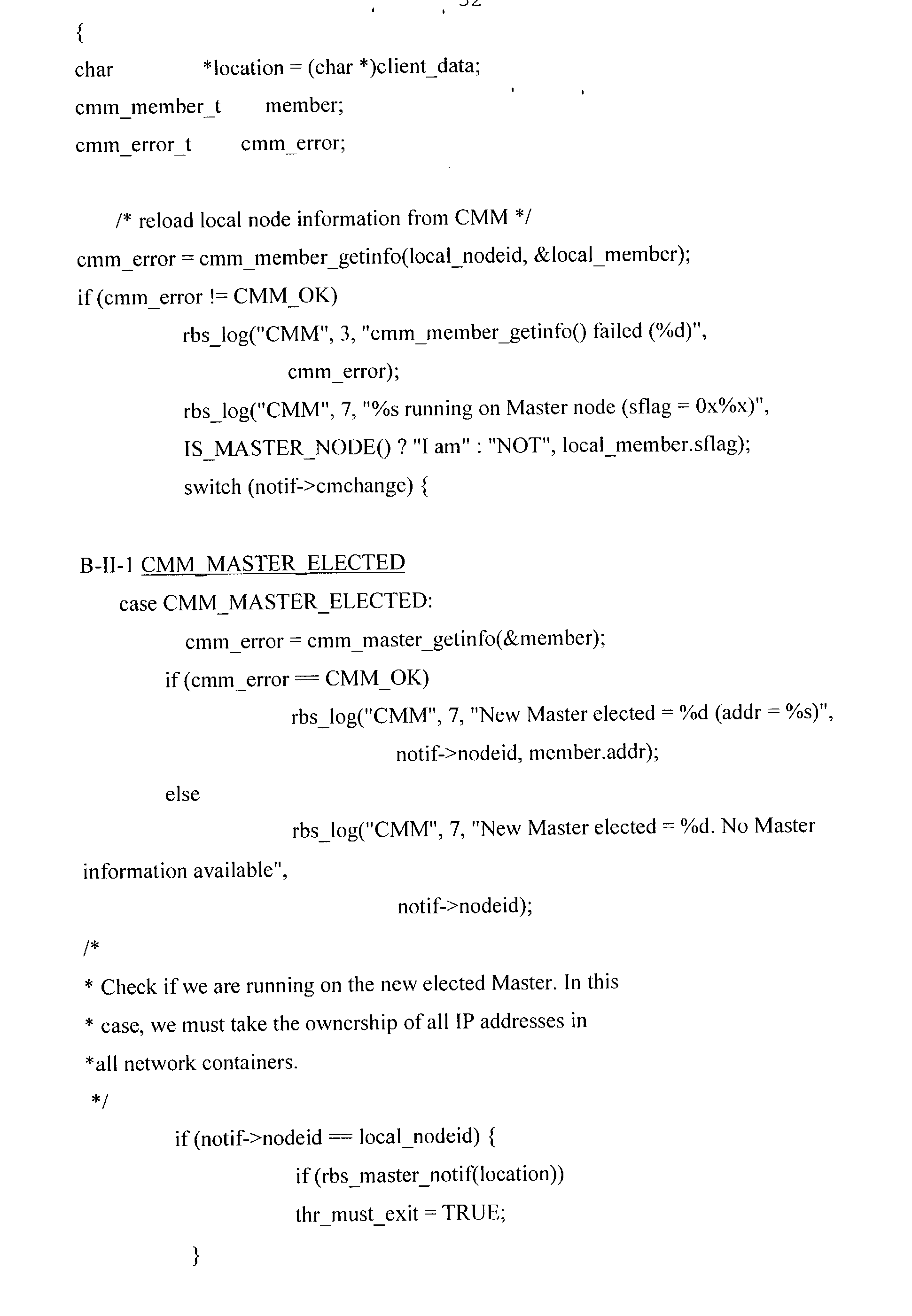
- the ownership of the current master node is done in Appendix B-I which corresponds to an extract from an open_dn( ) API function.
- the IS_MASTER_INIT_DN_DONE macro checks if master node specific initialization is already done, while the macro IS_MASTER_NODE checks if the current node is the master node.
- the set_ownership_dn( ) function searches in the given DHCP network container for entries not owned by the current Master node. For every entry found, the entry is updated to be owned by the current Master node.
- Appendix B-II-1 when a MASTER-ELECTED notification is received, the management layer of the node checks the node's role (operation 420 ). Thus, the table of entries may be modified by the new DHCP server using the new public module to indicate the monitorship of the current master node (operation 450 ).
- the node may be detected as failed:
- the notification ‘MEMBER LEFT’ is received from the management layer by the DHCP server.
- the DHCP server (more particularly the NHRBS public module) clears any lease (which may be pending time-out) and proceeds to the notification as described in Appendix B-11-3.
- the IP address is composed of 4 octet, e.g. 100.1.1.50 according to the version v4:
- first octet and second octet 100.1 designate the cluster to which the nodes belongs
- third octet 1 designates the sub-network used by the node
- fourth octet 50 designates the node and is called the hostnumber.
- the master node When receiving a request from a client node for an IP address allocation (operation 600 ) (MEMBER-JOINED), the master node provides an IP address (C-IP) from a first container for a first link level interface of the client node. If the client node accepts the IP address (operation 610 ), a mechanism is adapted to synchronize the IP address allocation for both containers. Thus, the second container may be bound to provide a given IP address to the second link level interface of the client node. The second address is calculated by changing the third octet to designate the second network. This address has the same hostnumber as in the IP address of the first link level interface and designates a different sub-net than the IP address of the first link level interface. The first and second containers are updated in a synchronous way (operation 620 ).
- the master node when a client node requesting an address (for example at or after a reboot time), the master node tries to provide only an IP address (C-IP).
- C-IP IP address
- the mechanism may use an internal cache of managed IP addresses. This cache is used to keep track of the IP address provided to the client node. Thus, the internal cache may provide the same IP address between several re-boots to a given node.
- the node which had this IP address may be assigned to the same IP address when it re-boots. This can happen when no other nodes have taken this IP address during the interval between the liberation of address and the re-boot of the node.
- the synchronization mechanism at operation 620 is also used if the node left the cluster for example.
- the DHCP server (using the NHRBS public module) is responsible for maintaining DHCP network containers coherency. As stated above, when an entry is assigned to a first link of a node (or freed) in one network container, an entry has to be assigned to the second link of the same node (or freed) in the other network container.
- the DHCP server (using the NHRBS public module) introduces synchronization methods between the network containers.
- the word “coherency” implies the synchronization mechanism.
- the third octet may be the octet 1 to designate the first link level interface, the octet 2 to designate the second link level interface, the octet 3 to designate that first and second link level interfaces are used in a redundant way.
- the address is divided into two addresses designating the first and second link level interfaces.
Landscapes
- Engineering & Computer Science (AREA)
- Computer Networks & Wireless Communication (AREA)
- Signal Processing (AREA)
- Environmental & Geological Engineering (AREA)
- Small-Scale Networks (AREA)
Abstract
Description
- This application hereby claims priority under 35 U.S.C § 119 to French patent application No. 0201228, filed Feb. 1, 2002, entitled, “Distributed Computer System Enhancing a Protocol Service to a Highly Available Service,” Attorney Docket No. SUN Aff. 31.
- The invention relates to a distributed computer system, for example a distributed computer system providing an extensible distributed software execution environment. Such an environment is a software platform, which may be intended for management and control applications for network components. Such a platform is composed of a group of cooperating nodes, also called a cluster, some nodes having hard disk and designated as diskfull and other nodes having no hard disk and designated as diskless. Such nodes use a standard network protocol, e.g. the DHCP protocol (Dynamic Host Configuration Protocol) described in the RFC 2131, March 1997, to provide administration information from diskfull nodes, called server nodes, to requesting nodes being possibly diskless nodes, called client nodes. Used in the Internet, the DHCP protocol provides IP address, Time Zone, network routing, mail, printing information and others various resources location to requesting nodes.
- Such a platform may have to be highly available. Thus, limits of the DHCP protocol concerning management of nodes appear in an environment having e.g. various server nodes, nodes needing to re-boot or being detected as failed or nodes having redundant links.
- A general aim of the present invention is to provide advances towards high availability.
- The invention concerns a distributed computer system comprising a group of nodes, said group of nodes having a first and a second node adapted to act as current monitor nodes, each node of the group of nodes having an identifier and a management layer being informed which node currently acts as the current monitor node. Each first and second node comprises,
- a protocol server adapted to associate and to send an address to a node requesting an address in the group of nodes,
- a memory adapted to store an association address-identifier of a node requesting an address. The protocol server is further capable of
- requesting the management layer of a node for an indication informing if said node acts as the current monitor node,
- attributing, to the current monitor node, the ownership of a list of associations, said list comprising associations of the memory of first node shared with associations of the memory of second node.
- The invention also concerns a method of managing a distributed computer system having a group of nodes, each node having an identifier, and comprising a first and a second node being adapted to act as the current monitor node of the group of nodes, comprises the following steps:
- a. requesting for an indication informing which one of the first or the second node acts as the current monitor node,
- b. attributing, to the current monitor node, the ownership of a list of associations address-identifier of nodes, this list comprising the associations from the first and second nodes,
- c. responsive to a reception of a request for an address of a requesting node in the first and the second nodes, associating and sending an address to the requesting node from the current monitor node,
- d. repeating steps a. to step c.
- Other alternative features and advantages of the invention will appear in the detailed description below and in the appended drawings.
- FIG. 1 is a general diagram of a distributed computer system comprising a diskfull node and a diskless node.
- FIG. 2 is a general diagram of a distributed computer system having redundant networks.
- FIG. 3 is a functional diagram of a node using a network protocol according to the invention.
- FIG. 4 is an architecture of a protocol as known.
- FIG. 5 is a functional diagram of a distributed computer system using a network protocol module according to an embodiment of the invention.
- FIG. 6 is a table of IP addresses stored according to the network protocol module of an embodiment of the invention.
- FIG. 7 is a flow-chart of the monitor node according to an embodiment of the invention.
- FIG. 8 is a flow-chart of the management of assignment of addresses according to an embodiment of the invention.
- FIG. 9 is a flow-chart of the address synchronization according to an embodiment of the invention.
- The following description is presented to enable any person skilled in the art to make and use the invention, and is provided in the context of a particular application and its requirements. Various modifications to the disclosed embodiments will be readily apparent to those skilled in the art, and the general principles defined herein may be applied to other embodiments and applications without departing from the spirit and scope of the present invention. Thus, the present invention is not intended to be limited to the embodiments shown, but is to be accorded the widest scope consistent with the principles and features disclosed herein.
- The data structures and code described in this detailed description are typically stored on a computer readable storage medium, which may be any device or medium that can store code and/or data for use by a computer system. This includes, but is not limited to, magnetic and optical storage devices such as disk drives, magnetic tape, CDs (compact discs) and DVDs (digital versatile discs or digital video discs), and computer instruction signals embodied in a transmission medium (with or without a carrier wave upon which the signals are modulated). For example, the transmission medium may include a communications network, such as the Internet.
- A portion of the disclosure of this patent document contains material which is subject to copyright protection. The copyright owner has no objection to the facsimile reproduction by anyone of the patent document or the patent disclosure, as it appears in the Patent and Trademark Office patent file or records, but otherwise reserves all copyright and/or author's rights whatsoever.
- Additionally, the detailed description is supplemented with the following Appendices:
- Appendix A contains specific data structures and API functions;
- Appendix B contains extracts of code according to an embodiment of the invention.
- These Appendices are placed apart for the purpose of clarifying the detailed description, and of enabling easier reference. They nevertheless form an integral part of the description of embodiments of the present invention. This applies to the drawings as well.
- This invention also encompasses embodiments in software code, especially when made available on any appropriate computer-readable medium. The expression “computer-readable medium” includes a storage medium such as magnetic or optic, as well as a transmission medium such as a digital or analog signal.
- This invention may be implemented in a network comprising computer systems. The hardware of such computer systems is for example as shown in FIG. 1, where in the computer system 10:
- 1-10 is a processor, e.g. an Ultra-Sparc (SPARC is a Trademark of SPARC International Inc);
- 2-10 is a program memory, e.g. an EPROM for BIOS;
- 3-10 is a working memory for software, data and the like, e.g. a RAM of any suitable technology (SDRAM for example); and
- 7-10 is a network interface device connected to a
communication medium 8, itself in communication with other computers such ascomputer system 11. Network interface device 7-10 may be an Ethernet device, a serial line device, or an ATM device, inter alia. Medium 8 may be based on wire cables, fiber optics, or radio-communications, for example. - The
computer system 10 may be a node amongst a group of nodes in a distributed computer system. Theother node 11 shown in FIG. 1 comprises the same components asnode 10, the components being designated with thesuffix 11. Thenode 11 further comprises a mass memory 4-11, e.g. one or more hard disks. - Thus,
node 10 is considered as a diskless node andnode 11 is considered as a diskfull node. - Data may be exchanged between the components of FIG. 1 through a bus system 9-10, respectively 9-11, schematically shown as a single bus for simplification of the drawing. As is known, bus systems may often include a processor bus, e.g. of the PCI type, connected via appropriate bridges to e.g. an ISA bus and/or an SCSI bus.
- FIG. 1 depicts two connected nodes.
- FIG. 2 shows an example of a group of nodes noted N* arranged as a cluster K. The cluster has a master node NM, a vice-master node NV and other nodes N2, N3 . . . Nn-1 and Nn. The qualification as master or as vice-master should be viewed as dynamic: one of the nodes acts as the master (resp. Vice-master) at a given time. However, for being eligible as a master or vice-master, a node needs to have the required “master” functionalities. A node being diskfull is considered to have at least partially these master functionalities.
- References to the drawings in the following description will use two different indexes or suffixes i and j, each of which may take anyone of the values: {M, V, 2 . . . n}, n+1 being the number of nodes in the cluster.
- In FIG. 2, each node Ni of cluster K is connected to a
first network 31 via links L1-i. Thisnetwork 31 is adapted to interconnect this node Ni with another node Nj through the link L1-j. If desired, the Ethernet link is also redundant: each node Ni of cluster K is connected to asecond network 32 via links L2-i. Thisnetwork 32 is adapted to interconnect this node Ni with another node Nj through the link L2-j. For example, if node N2 sends a packet to node Nn, the packet may be therefore duplicated to be sent on both networks. The mechanism of redundant network will be explained hereinafter. In fact, the foregoing description assumes that the second network for a node may be used in parallel with the first network. - Also, as an example, it is assumed that packets are generally built throughout the network in accordance with a transport protocol and a presentation protocol, e.g. the Ethernet Protocol and the Internet Protocol. Corresponding IP addresses are converted into Ethernet addresses on Ethernet network sections.
- In a more detailed exemplary embodiment and according to the Internet Protocol, a packet having an IP header comprises identification data as the source and destination fields, e.g. according to RFC-791. The source and destination fields are the IP address of the sending node and the IP address of the receiving node. It will be seen that a node has several IP addresses, for its various network interfaces. Although other choices are possible, it is assumed that the IP address of a node (in the source or destination field) is the address of its IP interface 100 (to be described).
- FIG. 3 shows an exemplary node Ni, in which the invention may be applied. Node Ni comprises, from top to bottom,
applications 13,management layer 11,network protocol stack 10, and Link level interfaces 12 and 14, respectively connected to networklinks Applications 13 andmanagement layer 11 can be implemented, for example, in software executed by the node'sCPU 1.Network protocol stack 10 and link level interfaces 12 and 14 can likewise be implemented in software and/or in dedicated hardware such as the node's network hardware interface 7. Node Ni may be part of a local or global network; in the foregoing exemplary description, the network is an Ethernet network, by way of example only. It is assumed that each node may be uniquely defined by a portion of its Ethernet address. Accordingly, as used hereinafter, “IP address” means an address uniquely designating a node in the network being considered (e.g. a cluster), whichever network protocol is being used. Although Ethernet is presently convenient, no restriction to Ethernet is intended. - Thus, in the example,
network protocol stack 10 comprises: - an
IP interface 100, having conventional Internet protocol (IP) functions 102, and a multipledata link interface 101, - above
IP interface 100, message protocol processing functions, e.g. anNFS function 104 and/or aDHCP function 105. This DHCP function is adapted to use the DHCP protocol as described in the RFC 2131, March 1997. -
Network protocol stack 10 is interconnected with the physical networks through first and second Link level interfaces 12 and 14, respectively. These are in turn connected to first andsecond network channels -
Link level interface 12 has an Internet address <IP —12> and a link level address <<LL —12>>. Incidentally, the doubled triangular brackets (<<. . . >>) are used only to distinguish link level addresses from global network addresses. Similarly,Link level interface 14 has an Internet address <IP —14>and a link level address <<LL —14>>. In a specific embodiment, where the physical network is Ethernet-based, interfaces 12 and 14 are Ethernet interfaces, and <<LL —12>>and <<LL —14>> are Ethernet addresses. - IP functions 102 comprise encapsulating a message coming from
upper layers upper layer - In redundant operation, the interconnection between
IP layer 102 and Link level interfaces 12 and 14 occurs through multipledata link interface 101. The multipledata link interface 101 also has an IP address <IP —10>, which is the node address in a packet sent from source node Ni. - References to Ethernet are exemplary, and other protocols may be used as well, both in
stack 10, including multipledata link interface 101, and/or in Link level interfaces 12 and 14. - Furthermore, where no redundancy is required,
IP layer 102 may directly exchange messages with anyone ofinterfaces data link interface 101. - It will be appreciated that layers 10 and 11 comprise components to provide a highly available link with
application layer 13 running on the node. Themanagement layer 11 also comprises a management and monitor entity of the node in the cluster, e.g. a Cluster Membership Monitor (CMM). - FIG. 4 illustrates an architecture of a DHCP (Dynamic Host Configuration Protocol) function or service which may have a multi-layered architecture. A diskfull node may have such a DHCP function adapted to receive DHCP request from diskless nodes.
- The DHCP
multi-layered architecture 116 is composed of aservice provider layer 126, aprivate layer 136 and an application/service provider layer 146. - As described in Appendix A-I-1, the
service provider layer 126 implements the service provider layer API functions described in Appendix A-I-4, exported by DHCP public modules and consumed by the private layer. Moreover, in Appendix A-I-2, A-I-3 this service provider layer defines the data structure stored in portions of disk accessible from the DHCP function, these portions of disk may be called “container”. There may be two types of containers called dhcp containers, the dhcptab container and the dhcp network container. The dhcptab container contains DHCP configuration data. There is only one instance of a dhcptab container maintained in the DHCP service. There can be any number of dhcp network containers, e.g. one for each network supported by the DHCP service. dhcp network containers contain records. - The
private layer 136 implements framework-related functions for locating and loading public modules, and provides “consumers API functions” used by consumers of the DHCP service data. - The Application/
service provider layer 146 contains all consumers of DHCP service data such as the DHCP server, the administration tools. - A boot of a node is hereinafter describes.
- When a new node is inserted in the system at initialization time or at any other time, the node is booted according to its software load configuration parameters. Particularly, this boot enables a diskless node to obtain its address from a diskfull node. In an embodiment, other addresses, e.g. the addresses of the various links of the diskless node, may be calculated from the diskless node's address as described hereinafter. In another embodiment, these other addresses may be also obtained during the boot of a diskless node.
- At initialization time, each node executes an initialization software providing various capabilities such as low level hardware configuration, low level hardware tests, operating system loading configuration, boot file configuration. On Sun hardware, such software may be called Open Boot Prom (OBP).
- According to the configuration of this initialization software (e.g. OBP), it launches a program to allow diskfull nodes to boot from their local disk or from the network, and to allow diskless nodes to boot from the network only. To boot from the network means to boot from the disk of a remote diskfull node in the network.
- In the context of this invention, boot of diskless nodes is particularly considered. When a diskless node boots, its initialization software (e.g. OBP) sends a broadcast request (e.g. DHCP discover) containing an identifier of the node, e.g. its Ethernet address, a board serial number or a MAC address, according to a particular protocol, e.g. DHCP. Thus, all nodes may receive this request. As seen, a diskfull node has a DHCP server adapted to reply to this request by providing
- its address as the DHCP server,
- the file path name of the diskfull node to download the default boot file on the diskless node.
- This DHCP server replies also by providing the address, e.g. IP address, of the diskless node. Each data or resources may be contained in portions of disk called DHCP containers.
- Several diskfull nodes have a DHCP server adapted to reply to a request of a diskless node, called a client's request. A function exported by a public module of the service provider layer of DHCP allows two DHCP servers to run on two separated diskfull nodes and sharing the same DHCP container.
- A diskfull node which reply to the request is considered as the owner diskfull node of the reply for all the associated resources. Problems hay occur when this owner diskfull node fails : the resources owned by this node are unavailable until re-boot of this node. Thus, some diskless nodes may be blocked and/or may be unabled to boot when this owner diskfull node fails.
- Another limit resides in the fact that the DHCP servers propose, at first boot of a node, a permanent address assignment for client nodes. If a node fails and the node is replaced by another with another identifier, the permanent IP address and the associated files in the DHCP containers are not re-assignable and are lost for the cluster.
- The DHCP protocol has still another limit for nodes comprising redundant network interfaces, such as redundant link level interfaces. Thus, the DHCP server assigns independently the address of a first link level interface and of a second link level interface of the same client node.
- FIG. 5 illustrates a partial cluster comprising two diskfull nodes. As herein above described, diskless nodes have the same structure as a diskfull node without a
memory 4 containingcontainers - Thus, each diskfull node comprises a
new DHCP function 106, also called thenew DHCP server 106, composed of acore DHCP server 1061, aconfiguration file tool 1062 and apublic module 1063 called e.g. NHRBS public module (Sun Netra Highly Reliable Boot Service). Thecore DHCP server 1061 corresponds to the known DHCP architecture of FIG. 4. Thus, theconfiguration file tool 1062 may be part of the Application/Service Provider layer as an administration tool and thepublic module 1063 may be part of the Service Provider layer. - The
configuration file tool 1062 is adapted to configure the core DHCP server so as to use thepublic module 1063. Then, other DHCP administration tools, as thisconfiguration file tool 1062, may also use the NHRBSpublic module 1063. Thisconfiguration file tool 1062 is adapted to generate a main configuration file in which are given the following information e.g. the name of thepublic module 1063 to use, the path name of the directory containing the various data containers, the network interfaces to monitor. Moreover, this configuration file tool if adapted to set or to modify values in the main configuration file. An example of a main configuration file generated by the configuration file tool is in Appendix A-II. In this example, the main configuration file containing DHCP service configuration parameters is stored in /etc/inet/dhcpsvc.conf, the RESOURCE line indicates the use of the NHRBS public module called SUNWnhrbs, the path name PATH=/SUNWcgha/remote/var/dhcp indicates the directory containing the various data containers and the INTERFACES line indicates the network interfaces to monitor. - The new
public module 1063 is a dynamic library automatically loaded at run-time by thecore DHCP server 1061. - The
DHCP server 106 is linked to amemory 4 havingcontainers e.g. containers configuration file tool 1062 indicates the link level interfaces of the diskfull node to which the DHCP server is connected to and that this DHCP server monitors. Thus, one container is designated for each link level interface monitored by the DHCP server. This container is called the network container. It may contain the data corresponding to request received at the link level interface of the diskfull node. Its address may indicate this link level interface address. Indeed, there may be one network container per sub-net managed by the DHCP server. Typically, a single server running on a system equipped with two network interfaces (hme0 and hme1 for example on the Netra systems), can manage two DHCP network containers, one for each interface. In the example of Appendix A-II, the network containers used by the SUNnhrbs module are named: SUNWnhrbsN_A_B_C_D where: - N is the version of the public module managing the container. (e.g. 1 for NHAS 2.0).
- A_B_C_D is the classical ASCII decimal representation for the sub-net corresponding to the network interface,
- For example, if interface hme0 is connected to sub-net 10.1.1.0 and hme1 to sub-net 10.1.2.0, the network containers will be named: SUNWnhrbs1 —10—1—1—0 and SUNWnhrbs1—10_1 —2—0. The content of the network containers used by SUNWnhrbs may be compatible with the ones used by the public module of the service provider layer.
- These
network containers public module 1063 to store data associated in a table T as illustrated in FIG. 6. - The
network container 41 may contain entries having different fields such as: - an C-IP field containing the IP address managed by the DHCP server,
- an C-ID field containing, when the IP address is assigned to a client node, the identifier of the client node, e.g. the MAC address of said node,
- an S-IP field containing the IP address of the DHCP server owning this entry, e.g. the server which manages it,
- a flag field being a bit-field containing information concerning the current status for the related entry, e.g. the “type of DHCP lease”. The term “lease” designates a given time enabling the use of the C_IP address for a node. The “lease” may be dynamic, meaning that at the end of this given time, the C_IP address corresponding to the “lease” may be renewed if needed. The “lease” may also be permanent, meaning the C_IP address is always assigned to a same node.
- Other fields may be added to specify other data related to the entry.
- The content of these
network containers configuration file tool 1062. - An example of dhcp network container configured by the configuration file tool is given in Appendix A-Ill for the sub-network 10 —1—1—0. As described hereinafter, the entry concerning the IP address 10.1.1.10 is manually bound to the node which identifier is 01080020F996DA. An example of dhcptab container is given in Appendix A-IV. This dhcptab container contains definition for macro's and symbols which can be applied to one or more network container entries. This container is not modified by the
configuration file tool 1062 of the invention. - The DHCP containers may be dynamically updated by the DHCP server at run-time, e.g. when entries are assigned to client nodes, when the lease is renewed, and by configuration files if configuration changes.
- In an embodiment, all the entries are configured for permanent lease for nodes of the cluster. The flag can designate e.g. a permanent lease.
- Reverting to FIG. 5, the containers of diskfull nodes may be shared by at least two diskfull nodes, the master node and the vice-master node. The diskfull nodes may use a NFS network (Network File System).
- Amongst diskfull nodes, the master NM and vice-master NVM nodes of the cluster are to be designated initially and at every boot of the system. Moreover, when the management layer 11-NM detects the master node NM as failed, the vice-master NVM is designated as the new master node of the cluster. The management layer 11-NVM detects the vice-master node as the current master node. The DHCP server of a node is advantageously linked to the management layer of the node.
- Indeed, at initialization time, the NHRBS public module of each diskfull node creates a thread enabling the new DHCP server to be connected to the management layer services to receive cluster membership notifications (MASTER-ELECTED, MEMBER-JOINED, MEMBER-LEFT). When such a notification is received, the new
public module 1063 is adapted to take the appropriate action as described in Appendix B-II and hereinafter in the different methods. - A first method of an embodiment of the invention is illustrated in FIG. 7 when a client node boots and requests for an IP address (operation 400).
- Each diskfull node receives the broadcast request (e.g. DHCP DISCOVER) in its DHCP server (operation 410). Each diskfull node has its,new DHCP server using the new public module to order the management layer to checks the node's role (operation 420). If the current diskfull node is not the current master node (operation 430), then the flow chart ends. If the current diskfull node is the current master node (operation 430), the table of entries may be modified by the new DHCP server using the new public module to indicate the monitorship of the current master node (operation 450). Thus, the new DHCP server using the new public module of the master current node changes the table of entries by setting all the server IP addresses (S-IP) as being the master node IP-address, such as getting the ownership of all the IP addresses configured. In an embodiment, the master node IP-address may be the multiple data link interface address of the master node. Thus, only the new DHCP server of the current master node replies to the broadcast request by providing the administration data comprising the required IP address C-IP to the node requesting an address (operation 460).
- The diskfull node being the vice-master node only receives the broadcast requests and the management layer notifications without replying when receiving them. This process and its corresponding components enables no IP-address (C-IP) to belong to a failed diskfull node.
- At initialization time, the ownership of the current master node is done in Appendix B-I which corresponds to an extract from an open_dn( ) API function. The IS_MASTER_INIT_DN_DONE macro checks if master node specific initialization is already done, while the macro IS_MASTER_NODE checks if the current node is the master node. The set_ownership_dn( ) function searches in the given DHCP network container for entries not owned by the current Master node. For every entry found, the entry is updated to be owned by the current Master node.
- In Appendix B-II-1, when a MASTER-ELECTED notification is received, the management layer of the node checks the node's role (operation 420). Thus, the table of entries may be modified by the new DHCP server using the new public module to indicate the monitorship of the current master node (operation 450).
- A second method of an embodiment of the invention is now illustrated with the flow chart of FIG. 8.
- When a node is detected as a failed node (MEMBER-LEFT) (operation 510), the flag value corresponding to the IP-address of said failed node is checked (operation 520). If said flag designates a “manual” value, the current master node does no action for this node (operation 530). This means a user may change manually, e.g. the hardware board and the corresponding identifier. If said flag does not designate a “manual” value, the current master node clears the node identifier from the table and the flag of said entry (operation 540). This operation liberates the resources in the containers corresponding to this entry.
- In
operation 510, the node may be detected as failed: - when the management layer sends a notification designating a node has left the cluster (shutdown or re-boot),
- when the server has provided data to the node requesting to join the cluster and has expected the node to join the cluster in an amount of time; this time has expired; the new public module according to the invention has checked the node presence and has decided the node has failed.
- Each time a node leaves the cluster (reboot or shutdown), the notification ‘MEMBER LEFT’ is received from the management layer by the DHCP server. In this case, the DHCP server (more particularly the NHRBS public module) clears any lease (which may be pending time-out) and proceeds to the notification as described in Appendix B-11-3.
- A third method of an embodiment of the invention is now illustrated with the flow chart of FIG. 9.
- The IP address is composed of 4 octet, e.g. 100.1.1.50 according to the version v4:
- first octet and second octet 100.1 designate the cluster to which the nodes belongs,
-
third octet 1 designates the sub-network used by the node, - fourth octet 50 designates the node and is called the hostnumber.
- When receiving a request from a client node for an IP address allocation (operation 600) (MEMBER-JOINED), the master node provides an IP address (C-IP) from a first container for a first link level interface of the client node. If the client node accepts the IP address (operation 610), a mechanism is adapted to synchronize the IP address allocation for both containers. Thus, the second container may be bound to provide a given IP address to the second link level interface of the client node. The second address is calculated by changing the third octet to designate the second network. This address has the same hostnumber as in the IP address of the first link level interface and designates a different sub-net than the IP address of the first link level interface. The first and second containers are updated in a synchronous way (operation 620).
- At
operation 600, when a client node requesting an address (for example at or after a reboot time), the master node tries to provide only an IP address (C-IP). The mechanism may use an internal cache of managed IP addresses. This cache is used to keep track of the IP address provided to the client node. Thus, the internal cache may provide the same IP address between several re-boots to a given node. - In the case of liberating an IP address, the node which had this IP address may be assigned to the same IP address when it re-boots. This can happen when no other nodes have taken this IP address during the interval between the liberation of address and the re-boot of the node.
- The synchronization mechanism at
operation 620 is also used if the node left the cluster for example. The DHCP server (using the NHRBS public module) is responsible for maintaining DHCP network containers coherency. As stated above, when an entry is assigned to a first link of a node (or freed) in one network container, an entry has to be assigned to the second link of the same node (or freed) in the other network container. - The DHCP server (using the NHRBS public module) introduces synchronization methods between the network containers. The word “coherency” implies the synchronization mechanism.
- Thus, the third octet may be the
octet 1 to designate the first link level interface, theoctet 2 to designate the second link level interface, theoctet 3 to designate that first and second link level interfaces are used in a redundant way. In the last case, the address is divided into two addresses designating the first and second link level interfaces. - The invention is not limited to the herein above-described features.
- Thus, other network containers may be used if other link level interfaces are provided for a node.
- The foregoing descriptions of embodiments of the present invention have been presented for purposes of illustration and description only. They are not intended to be exhaustive or to limit the present invention to the forms disclosed. Accordingly, many modifications and variations will be apparent to practitioners skilled in the art. Additionally, the above disclosure is not intended to limit the present invention. The scope of the present invention is defined by the appended claims.


Claims (18)
Applications Claiming Priority (2)
| Application Number | Priority Date | Filing Date | Title |
|---|---|---|---|
| FR0201228 | 2002-02-01 | ||
| FR0201228 | 2002-02-01 |
Publications (2)
| Publication Number | Publication Date |
|---|---|
| US20030177218A1 true US20030177218A1 (en) | 2003-09-18 |
| US7243142B2 US7243142B2 (en) | 2007-07-10 |
Family
ID=27839169
Family Applications (1)
| Application Number | Title | Priority Date | Filing Date |
|---|---|---|---|
| US10/354,334 Active 2025-05-23 US7243142B2 (en) | 2002-02-01 | 2003-01-29 | Distributed computer system enhancing a protocol service to a highly available service |
Country Status (1)
| Country | Link |
|---|---|
| US (1) | US7243142B2 (en) |
Cited By (11)
| Publication number | Priority date | Publication date | Assignee | Title |
|---|---|---|---|---|
| US20030145117A1 (en) * | 2002-01-30 | 2003-07-31 | Bhat Gangadhar D. | Intermediate driver having a fail-over function for a virtual network interface card in a system utilizing infiniband architecture |
| US20060067274A1 (en) * | 2004-09-30 | 2006-03-30 | Avaya Technology Corp. | Method and apparatus for merging call components during call reconstruction |
| US20080310707A1 (en) * | 2007-06-15 | 2008-12-18 | Microsoft Corporation | Virtual reality enhancement using real world data |
| US20090167787A1 (en) * | 2007-12-28 | 2009-07-02 | Microsoft Corporation | Augmented reality and filtering |
| US20130067048A1 (en) * | 2011-09-12 | 2013-03-14 | Nitin Narang | Multi-Entity Management |
| WO2013142023A1 (en) * | 2012-03-20 | 2013-09-26 | Symantec Corporation | Cluster wide consistent detection of interconnect failures |
| US20150249618A1 (en) * | 2014-03-02 | 2015-09-03 | Plexistor Ltd. | Peer to peer ownership negotiation |
| US9515899B2 (en) | 2012-12-19 | 2016-12-06 | Veritas Technologies Llc | Providing optimized quality of service to prioritized virtual machines and applications based on quality of shared resources |
| US10942831B2 (en) * | 2018-02-01 | 2021-03-09 | Dell Products L.P. | Automating and monitoring rolling cluster reboots |
| US11128568B2 (en) * | 2017-04-24 | 2021-09-21 | International Business Machines Corporation | Routing packets in multiple destination networks with overlapping address spaces |
| US11765127B1 (en) * | 2022-04-20 | 2023-09-19 | Dell Products, L.P. | Pluggable network address management stack |
Families Citing this family (21)
| Publication number | Priority date | Publication date | Assignee | Title |
|---|---|---|---|---|
| US7483369B2 (en) | 2003-09-30 | 2009-01-27 | Avaya Inc. | Method and apparatus for migrating to an alternate call controller |
| US7496056B2 (en) * | 2005-01-04 | 2009-02-24 | Avaya Inc. | Conference connections using dynamic topology switching for IP and circuit-switched fabrics |
| US7457249B2 (en) * | 2005-01-04 | 2008-11-25 | Avaya, Inc. | Alternate routing of media connections within a single communications system across public or private network facilities |
| US7564793B2 (en) * | 2005-01-04 | 2009-07-21 | Avaya Inc. | In-band call association signaling for a single number destination |
| US20060146859A1 (en) * | 2005-01-04 | 2006-07-06 | Avaya Technology Corp. | Alternate routing of media connections within a single communications system across public or private network facilities |
| US7613106B2 (en) * | 2005-01-04 | 2009-11-03 | Avaya Inc. | Dial plan transparency for fragmented networks |
| US8462637B1 (en) | 2005-01-04 | 2013-06-11 | Sheridan Ross P.C. | Dial plan routing for fragmented networks |
| GB0501697D0 (en) * | 2005-01-27 | 2005-03-02 | Ibm | Controlling service failover in clustered storage apparatus networks |
| KR100727999B1 (en) * | 2005-10-14 | 2007-06-14 | 삼성전자주식회사 | Method and apparatus for efficiently managing an information for a UPnP device |
| US8122108B2 (en) * | 2006-05-16 | 2012-02-21 | Oracle International Corporation | Database-less leasing |
| US7661015B2 (en) * | 2006-05-16 | 2010-02-09 | Bea Systems, Inc. | Job scheduler |
| US9384103B2 (en) * | 2006-05-16 | 2016-07-05 | Oracle International Corporation | EJB cluster timer |
| US7680956B2 (en) * | 2006-10-24 | 2010-03-16 | Cisco Technology, Inc. | Communicating additional information in a DNS update response by requesting deletion of a specific record |
| US8495044B2 (en) * | 2009-09-02 | 2013-07-23 | Microsoft Corporation | File system node updates |
| US10419390B2 (en) | 2016-06-27 | 2019-09-17 | International Business Machines Corporation | Using dynamic host configuration protocol to protect data |
| US9910666B1 (en) * | 2016-08-22 | 2018-03-06 | International Business Machines Corporation | Implementing locale management on PaaS: live locale object update |
| US10169048B1 (en) | 2017-06-28 | 2019-01-01 | International Business Machines Corporation | Preparing computer nodes to boot in a multidimensional torus fabric network |
| US10571983B2 (en) | 2017-06-28 | 2020-02-25 | International Business Machines Corporation | Continuously available power control system |
| US10088643B1 (en) | 2017-06-28 | 2018-10-02 | International Business Machines Corporation | Multidimensional torus shuffle box |
| US10356008B2 (en) | 2017-06-28 | 2019-07-16 | International Business Machines Corporation | Large scale fabric attached architecture |
| US12021926B1 (en) * | 2023-08-21 | 2024-06-25 | Amazon Technologies, Inc. | Lockless, leaderless protocol for scalable applications |
Citations (2)
| Publication number | Priority date | Publication date | Assignee | Title |
|---|---|---|---|---|
| US6249813B1 (en) * | 1998-08-06 | 2001-06-19 | Mci Communications Corporation | Automated method of and apparatus for internet address management |
| US6574197B1 (en) * | 1998-07-03 | 2003-06-03 | Mitsubishi Denki Kabushiki Kaisha | Network monitoring device |
-
2003
- 2003-01-29 US US10/354,334 patent/US7243142B2/en active Active
Patent Citations (2)
| Publication number | Priority date | Publication date | Assignee | Title |
|---|---|---|---|---|
| US6574197B1 (en) * | 1998-07-03 | 2003-06-03 | Mitsubishi Denki Kabushiki Kaisha | Network monitoring device |
| US6249813B1 (en) * | 1998-08-06 | 2001-06-19 | Mci Communications Corporation | Automated method of and apparatus for internet address management |
Cited By (21)
| Publication number | Priority date | Publication date | Assignee | Title |
|---|---|---|---|---|
| US20030145117A1 (en) * | 2002-01-30 | 2003-07-31 | Bhat Gangadhar D. | Intermediate driver having a fail-over function for a virtual network interface card in a system utilizing infiniband architecture |
| US6963932B2 (en) * | 2002-01-30 | 2005-11-08 | Intel Corporation | Intermediate driver having a fail-over function for a virtual network interface card in a system utilizing Infiniband architecture |
| US20060067274A1 (en) * | 2004-09-30 | 2006-03-30 | Avaya Technology Corp. | Method and apparatus for merging call components during call reconstruction |
| US7366110B2 (en) * | 2004-09-30 | 2008-04-29 | Avaya Technology Corp. | Method and apparatus for merging call components during call reconstruction |
| US20080310707A1 (en) * | 2007-06-15 | 2008-12-18 | Microsoft Corporation | Virtual reality enhancement using real world data |
| US20090167787A1 (en) * | 2007-12-28 | 2009-07-02 | Microsoft Corporation | Augmented reality and filtering |
| US8264505B2 (en) | 2007-12-28 | 2012-09-11 | Microsoft Corporation | Augmented reality and filtering |
| US8687021B2 (en) | 2007-12-28 | 2014-04-01 | Microsoft Corporation | Augmented reality and filtering |
| US20130067048A1 (en) * | 2011-09-12 | 2013-03-14 | Nitin Narang | Multi-Entity Management |
| US9407506B2 (en) * | 2011-09-12 | 2016-08-02 | Microsoft Technology Licensing, Llc | Multi-entity management |
| US8892936B2 (en) | 2012-03-20 | 2014-11-18 | Symantec Corporation | Cluster wide consistent detection of interconnect failures |
| WO2013142023A1 (en) * | 2012-03-20 | 2013-09-26 | Symantec Corporation | Cluster wide consistent detection of interconnect failures |
| US9515899B2 (en) | 2012-12-19 | 2016-12-06 | Veritas Technologies Llc | Providing optimized quality of service to prioritized virtual machines and applications based on quality of shared resources |
| US11599374B2 (en) | 2012-12-19 | 2023-03-07 | Veritas Technologies Llc | System and method for providing preferential I/O treatment to devices that host a critical virtual machine |
| US20150249618A1 (en) * | 2014-03-02 | 2015-09-03 | Plexistor Ltd. | Peer to peer ownership negotiation |
| US10031933B2 (en) * | 2014-03-02 | 2018-07-24 | Netapp, Inc. | Peer to peer ownership negotiation |
| US10430397B2 (en) | 2014-03-02 | 2019-10-01 | Netapp, Inc. | Peer to peer ownership negotiation |
| US10853339B2 (en) | 2014-03-02 | 2020-12-01 | Netapp Inc. | Peer to peer ownership negotiation |
| US11128568B2 (en) * | 2017-04-24 | 2021-09-21 | International Business Machines Corporation | Routing packets in multiple destination networks with overlapping address spaces |
| US10942831B2 (en) * | 2018-02-01 | 2021-03-09 | Dell Products L.P. | Automating and monitoring rolling cluster reboots |
| US11765127B1 (en) * | 2022-04-20 | 2023-09-19 | Dell Products, L.P. | Pluggable network address management stack |
Also Published As
| Publication number | Publication date |
|---|---|
| US7243142B2 (en) | 2007-07-10 |
Similar Documents
| Publication | Publication Date | Title |
|---|---|---|
| US20030177218A1 (en) | Distributed computer system enhancing a protocol service to a highly available service | |
| US7899047B2 (en) | Virtual network with adaptive dispatcher | |
| US7978631B1 (en) | Method and apparatus for encoding and mapping of virtual addresses for clusters | |
| US7257817B2 (en) | Virtual network with adaptive dispatcher | |
| US7788522B1 (en) | Autonomous cluster organization, collision detection, and resolutions | |
| US7546354B1 (en) | Dynamic network based storage with high availability | |
| US7263560B2 (en) | Decentralized peer-to-peer advertisement | |
| US7657597B2 (en) | Instant messaging using distributed indexes | |
| US7197565B2 (en) | System and method of using a pipe advertisement for a peer-to-peer network entity in peer-to-peer presence detection | |
| CN103581276B (en) | Cluster management device, system, service customer end and correlation method | |
| US9720682B2 (en) | Integrated software and hardware system that enables automated provisioning and configuration of a blade based on its physical location | |
| US20070083723A1 (en) | Highly-available blade-based distributed computing system | |
| US20060206611A1 (en) | Method and system for managing programs with network address | |
| US7401114B1 (en) | Method and apparatus for making a computational service highly available | |
| CN111615066A (en) | Distributed micro-service registration and calling method based on broadcast | |
| US20080155082A1 (en) | Computer-readable medium storing file delivery program, file delivery apparatus, and distributed file system | |
| CN114070822B (en) | Kubernetes Overlay IP address management method | |
| US20040143654A1 (en) | Node location management in a distributed computer system | |
| US7836351B2 (en) | System for providing an alternative communication path in a SAS cluster | |
| CN111010304A (en) | Method for integrating Dubbo service and Kubernetes system | |
| CN111641730A (en) | Scalable address resolution | |
| WO2023016415A1 (en) | Node for running container group, and management system and method of container group | |
| US20240089352A1 (en) | Udp message distribution method, udp message distribution apparatus, electronic device and computer readable storage medium | |
| JP2021114767A5 (en) | ||
| CN102577249B (en) | The example set of the connection of dynamic addressing main frame |
Legal Events
| Date | Code | Title | Description |
|---|---|---|---|
| AS | Assignment |
Owner name: SUN MICROSYSTEMS, INC., CALIFORNIA Free format text: ASSIGNMENT OF ASSIGNORS INTEREST;ASSIGNORS:POIROT, DIDIER;ARMAND, FRANCOIS;MCKINTY, STEPHEN;REEL/FRAME:014060/0058;SIGNING DATES FROM 20030411 TO 20030429 |
|
| STCF | Information on status: patent grant |
Free format text: PATENTED CASE |
|
| CC | Certificate of correction | ||
| FPAY | Fee payment |
Year of fee payment: 4 |
|
| FPAY | Fee payment |
Year of fee payment: 8 |
|
| AS | Assignment |
Owner name: ORACLE AMERICA, INC., CALIFORNIA Free format text: MERGER AND CHANGE OF NAME;ASSIGNORS:ORACLE USA, INC.;SUN MICROSYSTEMS, INC.;ORACLE AMERICA, INC.;REEL/FRAME:037302/0772 Effective date: 20100212 |
|
| MAFP | Maintenance fee payment |
Free format text: PAYMENT OF MAINTENANCE FEE, 12TH YEAR, LARGE ENTITY (ORIGINAL EVENT CODE: M1553); ENTITY STATUS OF PATENT OWNER: LARGE ENTITY Year of fee payment: 12 |