US20030155152A1 - Method of conducting in situ measurements of properties of a reservoir fluid - Google Patents
Method of conducting in situ measurements of properties of a reservoir fluid Download PDFInfo
- Publication number
- US20030155152A1 US20030155152A1 US10/257,486 US25748603A US2003155152A1 US 20030155152 A1 US20030155152 A1 US 20030155152A1 US 25748603 A US25748603 A US 25748603A US 2003155152 A1 US2003155152 A1 US 2003155152A1
- Authority
- US
- United States
- Prior art keywords
- fluid
- drill string
- reservoir
- casing
- reservoir fluid
- Prior art date
- Legal status (The legal status is an assumption and is not a legal conclusion. Google has not performed a legal analysis and makes no representation as to the accuracy of the status listed.)
- Abandoned
Links
- 239000012530 fluid Substances 0.000 title claims abstract description 126
- 238000012625 in-situ measurement Methods 0.000 title claims abstract description 7
- 238000000034 method Methods 0.000 title claims description 13
- 238000005259 measurement Methods 0.000 claims abstract description 40
- 238000004458 analytical method Methods 0.000 claims abstract description 23
- 229930195733 hydrocarbon Natural products 0.000 claims abstract description 21
- 150000002430 hydrocarbons Chemical class 0.000 claims abstract description 21
- 239000004215 Carbon black (E152) Substances 0.000 claims abstract description 18
- XLYOFNOQVPJJNP-UHFFFAOYSA-N water Substances O XLYOFNOQVPJJNP-UHFFFAOYSA-N 0.000 claims abstract description 14
- 238000004891 communication Methods 0.000 claims abstract description 9
- 238000011144 upstream manufacturing Methods 0.000 claims abstract description 6
- 238000011065 in-situ storage Methods 0.000 claims description 11
- 235000013619 trace mineral Nutrition 0.000 claims description 7
- 239000011573 trace mineral Substances 0.000 claims description 7
- 230000033001 locomotion Effects 0.000 claims description 3
- 230000001747 exhibiting effect Effects 0.000 claims description 2
- 238000012360 testing method Methods 0.000 abstract description 20
- 230000004308 accommodation Effects 0.000 abstract 1
- 238000005070 sampling Methods 0.000 description 27
- 230000015572 biosynthetic process Effects 0.000 description 21
- 238000005755 formation reaction Methods 0.000 description 21
- 238000005553 drilling Methods 0.000 description 14
- 238000004519 manufacturing process Methods 0.000 description 12
- 238000012856 packing Methods 0.000 description 7
- 239000007788 liquid Substances 0.000 description 4
- 230000000694 effects Effects 0.000 description 2
- 238000005086 pumping Methods 0.000 description 2
- 238000007789 sealing Methods 0.000 description 2
- 229910000831 Steel Inorganic materials 0.000 description 1
- 239000002253 acid Substances 0.000 description 1
- 230000005540 biological transmission Effects 0.000 description 1
- 150000001805 chlorine compounds Chemical class 0.000 description 1
- 239000003599 detergent Substances 0.000 description 1
- 238000006073 displacement reaction Methods 0.000 description 1
- 238000005516 engineering process Methods 0.000 description 1
- 238000002347 injection Methods 0.000 description 1
- 239000007924 injection Substances 0.000 description 1
- 238000011835 investigation Methods 0.000 description 1
- 230000035699 permeability Effects 0.000 description 1
- 238000012545 processing Methods 0.000 description 1
- 230000005855 radiation Effects 0.000 description 1
- 238000011084 recovery Methods 0.000 description 1
- 239000004576 sand Substances 0.000 description 1
- 229920006395 saturated elastomer Polymers 0.000 description 1
- 230000008054 signal transmission Effects 0.000 description 1
- 238000004611 spectroscopical analysis Methods 0.000 description 1
- 239000010959 steel Substances 0.000 description 1
- 238000003860 storage Methods 0.000 description 1
- 239000000126 substance Substances 0.000 description 1
- 238000012546 transfer Methods 0.000 description 1
Images


Classifications
-
- E—FIXED CONSTRUCTIONS
- E21—EARTH OR ROCK DRILLING; MINING
- E21B—EARTH OR ROCK DRILLING; OBTAINING OIL, GAS, WATER, SOLUBLE OR MELTABLE MATERIALS OR A SLURRY OF MINERALS FROM WELLS
- E21B47/00—Survey of boreholes or wells
- E21B47/12—Means for transmitting measuring-signals or control signals from the well to the surface, or from the surface to the well, e.g. for logging while drilling
- E21B47/14—Means for transmitting measuring-signals or control signals from the well to the surface, or from the surface to the well, e.g. for logging while drilling using acoustic waves
- E21B47/16—Means for transmitting measuring-signals or control signals from the well to the surface, or from the surface to the well, e.g. for logging while drilling using acoustic waves through the drill string or casing, e.g. by torsional acoustic waves
-
- E—FIXED CONSTRUCTIONS
- E21—EARTH OR ROCK DRILLING; MINING
- E21B—EARTH OR ROCK DRILLING; OBTAINING OIL, GAS, WATER, SOLUBLE OR MELTABLE MATERIALS OR A SLURRY OF MINERALS FROM WELLS
- E21B33/00—Sealing or packing boreholes or wells
- E21B33/10—Sealing or packing boreholes or wells in the borehole
- E21B33/12—Packers; Plugs
- E21B33/124—Units with longitudinally-spaced plugs for isolating the intermediate space
-
- E—FIXED CONSTRUCTIONS
- E21—EARTH OR ROCK DRILLING; MINING
- E21B—EARTH OR ROCK DRILLING; OBTAINING OIL, GAS, WATER, SOLUBLE OR MELTABLE MATERIALS OR A SLURRY OF MINERALS FROM WELLS
- E21B49/00—Testing the nature of borehole walls; Formation testing; Methods or apparatus for obtaining samples of soil or well fluids, specially adapted to earth drilling or wells
- E21B49/08—Obtaining fluid samples or testing fluids, in boreholes or wells
- E21B49/081—Obtaining fluid samples or testing fluids, in boreholes or wells with down-hole means for trapping a fluid sample
Definitions
- the invention regards a method of conducting in situ measurements of properties of reservoir fluids by means of measuring instruments/apparatuses enclosed in a casing connected to the outer, free end of a string of tubulars in a wellbore/well that extends at least down to the hydrocarbon-containing layer of the reservoir, where the inherent pressure of the reservoir fluid (the reservoir pressure) ensures the inflow of reservoir fluid to the instrument/apparatus casing through an inlet or possibly a combined inlet/outlet, and where signals that are generated via electronics etc. on the basis of measurement results obtained in situ, are transmitted further to the surface position, possibly for further analysis.
- the above methods each have different advantages and disadvantages.
- the strong point of full production testing is that data may be collected from a large volume of reservoir fluid, ensuring highly reliable data.
- the main weak point is the great costs incurred, for instance when hiring a rig and other necessary equipment.
- Another significant disadvantage is that it will be necessary somehow to handle the large volume of reservoir fluid that is transported up to the surface. At present, this is normally done by burning the oil and gas, which is damaging to the environment. Consequently, the oil companies aim to cease such burning after 2003.
- Essential advantages of the use of sampling and measuring equipment that is lowered into the well by a wire string is that it allows continuous sampling of the reservoir fluid during drilling, and that it may be carried out at a considerably lower cost than full production testing.
- the main weak point of the equipment is the limitations on what the equipment can provide in the way of data regarding relevant reservoir fluid parameters. As an example, it is not possible to obtain essential data regarding the flow conditions in the reservoir fluid. Also, the equipment can not be used in connection with saturated gas reservoirs, as the pressure and temperature can not be stabilised. This weakness is further enhanced in consequence of very small volumes of reservoir fluid being extracted, and of the equipment having to be manipulated from the surface. The latter fact may in addition lead to the measurement results for the reservoir fluid becoming unreliable.
- Such errors in the measurement results may among other things be due to the equipment not being positioned correctly in the reservoir during sampling, to the reservoir fluid at the sampling location having been contaminated by the drill fluid used during drilling, and to sand that follows the reservoir fluid upon sampling causing cracks and leakage in the equipment.
- U.S. Pat. No. 5,095,745 describes a sampling tool with an analysis chamber, which following the analysis delivers the well fluid back to the isolated oil-containing layer. More specifically, this US patent specification discloses a method and an apparatus/tool for testing subsea formations, in particular formations exhibiting a very particular permeability.
- This known device comprises a well fluid-receiving chamber provided with a piston that may be moved in a reciprocal motion in the chamber. The length of stroke for the piston is very limited and is determined by the dimensions of the chamber in the axial direction of the piston, and the device is therefore unsuitable for certain measurements that require the passage of a substantial volume of fluid into and through the casing of the measuring instrument in the space of a certain period of time.
- U.S. Pat. No. 5,201,220 describes a gas detector module with a flow line that returns the formation fluid to the well after analysis.
- test fluid multiphase fluid, possibly containing gas
- a multi-core cable in this subsea arrangement is only intended for transmission of electrical signals, and the processing system is located at a higher level than the wellbore, possibly at a surface position.
- U.S. Pat. No. 5,799,733 describes a system in which no provisions have been made for return of the liquid reservoir fluid to the exact same hydrocarbon-containing layer from which it was previously taken for measurement/analysis purposes.
- This known system is to allow fluid sampling and measurements, and comprises a powered formation pump as an essential component.
- the subsea-operating device that forms part of this system, and which includes said pump, is connected to a production string.
- the production string provides the transfer of motive fluid that is pumped from a surface position to drive the subsea rotary motor for the formation pump. Pumping of in situ fluid to be tested into a sampling pipe takes place via said pump.
- the conditions of such in situ subsea fluid tests have been made suitable for large throughflow volumes and long throughflow periods for said measuring instruments/apparatuses, so that a substantial volume of reservoir fluid may be received and handled from the start of the test and until the end of it, and where provisions are also made for return of this substantial volume of test fluid to the original hydrocarbon-containing layer of the reservoir.
- measurements such as flow or volume measurements are thus initiated with the instrument/apparatus casing in said in situ position and in fluid communication with the string of tubulars, which measurements are of the type that—in order to obtain measurement results with a high degree of accuracy—require the respective measuring instrument positioned in situ to have a throughflow of a substantial volume of test fluid for a considerable throughflow period.
- This substantial volume of fluid is then received and handled for subsequent return to the original oil-containing layer of the reservoir, by being passed into the string of tubulars in fluid communication with the measuring instruments/apparatuses-containing casing.
- the flow of the test fluid into the inlet of the instrument casing takes place in a known manner under utilisation of the inherent pressure of the reservoir fluid (the reservoir pressure), which also ensures that liquid fluids that have flowed through a respective measuring instrument is led further into and up through the bore of the string, in which is arranged a freely reciprocating piston that may be influenced by pressurised fluid both upstream (by the reservoir fluid when it flows out of the oil-containing layer) and downstream (from a fluid such as water or N 2 ) on the opposite, upper side of the piston, which fluid may be pressurised by pumping action and increase the pressure in the bore of the string at the downstream end of the piston, so that a build-up of pressure takes place here, which pressure will, after a while, exceed the pressure of the reservoir fluid by the upstream end of the piston.
- a piston separates the reservoir fluid, which has had an opportunity to flow through respective measuring instruments in the casing and then up into the bore of the tubular string, from water or N 2 .
- Said water or N 2 is also used to force drilling mud/fluid from the drill string or production string and out into the surrounding annulus formed between the tubular string and the borehole wall.
- the piston After perforation in a manner that is known per so, the piston will travel upward upon admission of reservoir fluid at a rate that is controlled by a valve/choke.
- the inflow of reservoir fluid can thereby be measured by reading the volume of fluid (preferably water or N 2 ) that has flowed into a tank on the surface during the inflow.
- the reservoir fluid has risen in the string to a level where the fluid has reached the safety valve, often called BOP, on the seabed or the surface
- BOP safety valve
- the piston is brought to a halt in a seat inserted in the tubular string. All the desired tests have then been conducted downhole, and the reservoir fluid is forced back to the reservoir as indicated above.
- FIG. 1 shows a schematic cutout in the lower part of an exploration well being drilled in a ground formation
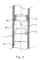
- FIG. 2 is a large-scale detail drawing, partly with a section through the tubular string, and in which the piston movably arranged in the bore of this, and stationary seat for same, may be seen.
- the well is drilled by means of drilling equipment comprising a drill bit 15 with an associated drill string 4 , the in situ sampling, and flow and volume measurements or the other analyses in the reservoir fluid being carried out by use of equipment provided inside an associated casing 7 that encloses the drill string above the drill bit 15 .
- the well is sealed off in an area by the hydrocarbon-containing layer 2 of the formation by means of packings 5 , 6 that are arranged externally on the casing 7 and have expanded to abut the wall of the borehole in a sealing manner.
- the embodiment of the invention is adapted to use in in situ sampling, flow and volume measurements, and any other analysis in reservoir fluid that is encountered in a ground formation 1 during drilling of an exploration well 3 for hydrocarbons but there is obviously nothing to prevent the present invention from being used in a different context, e.g. in a ground formation that has already been put into full production.
- the aim is, among other things, for typical properties or parameters of the reservoir fluid that is encountered in the ground formation 1 to be determined with the greatest possible degree of accuracy, without a large volume of hydrocarbons having to be brought out of the well 3 and up to the surface.
- the well 3 is sealed off in an area immediately above and below (by 5 and 6 ) the hydrocarbon-containing layer 2 of the ground formation 1 .
- reservoir fluid from the hydrocarbon-containing layer 2 is introduced to a drill string 4 that has at least been passed through the sealed-off area of the well 3 .
- the sampling, the flow and volume measurements and the other analyses in the reservoir fluid are conducted in the sealed-off area of the well 3 .
- this will only take place when the drill string 4 has been closed off and filled with incoming reservoir fluid.
- the sampling and respective measurements or analyses are only conducted after a large volume of reservoir fluid has been introduced into the drill string 4 .
- This allows samples or measurements to be taken in a reservoir fluid that has stabilised after drilling, and which essentially contains no drill fluid. This as a consequence of, among other things, the previously mentioned piston 17 separating the reservoir fluid RV in chamber 19 below the piston 17 from the above water or N 2 .
- Said water or N 2 may in an initial position or in a transitional position be pressurised in order to force drilling mud/fluid from the drill string/production string 4 and out into the annulus 3 .
- the piston 17 will travel upward (arrow A) into the string 4 as reservoir fluid RV is admitted into the drilling section 19 located below the piston 17 and expands as the piston 17 is moved up.
- measuring or analysis equipment 9 - 12 that has been introduced into the well 3 together with the drill string 4 , the reservoir fluid from the drill string 4 is returned to the hydrocarbon-containing layer 2 of the ground formation 1 in a suitable manner.
- sampling, measuring or analysis equipment 912 is withdrawn from the well 3 along with the drill string 4 , in order to allow the small amount of reservoir fluid that comes up to the surface with it to be examined more closely in the laboratory. This avoids a large volume of reservoir fluid having to be carried to the surface, as mentioned previously.
- the well 3 is only sealed off following a stop in drilling after the respective hydrocarbon-containing layer 2 of the ground formation 1 has been passed.
- the drilling may if necessary continue down towards underlying layers (not shown), in order for these to be sampled, measured or analysed in a similar manner.
- the well 3 Prior to the sampling, flow and volume measurements or the other analyses, the well 3 will normally be logged and washed out before being sealed off.
- the washout can be carried out by means of a detergent that is circulated in the well 3 .
- the drill fluid When reservoir fluid is then introduced into the drill string 4 , the drill fluid is circulated out through a suitable valve between the drill string 4 and the annulus formed between the wall of the borehole and the drill string 4 , and the drill fluid is transported further from the annulus for storage in tanks or similar (not shown) on the surface.
- the drill fluid is replaced by a gas/liquid (N 2 /water) that is known and prepared for the test phase by use of added trace elements.
- sampling, flow and volume measurements or the other analyses is are conducted continuously, and after the drill string has been filled with reservoir fluid in a controlled manner by means of a downhole valve. However this does not prevent the sampling, flow and volume measurements or the other analyses from being carried out at another appropriate time. This may for instance be the case when it is desirable that continuous measurements be carried out during the introduction of the reservoir fluid into the drill string 4 .
- the set of figures show an exploration well 3 drilled in a manner that is known per se, by means of a drill bit 15 with an associated drill string 4 , and in which the pressure is equalised during drilling by use of a drill fluid with added trace elements.
- the drill string 4 may for instance be coiled tubing etc.
- Above the drill bit 15 the drill string 4 is enclosed in an associated casing 7 having a length that may be greater than the height of the hydrocarbon-containing layer 2 of the ground formation 1 .
- the casing 7 may be made from steel that is highly resistant against the effects of an acid environment with a high content of chlorides.
- the respective end of the casing part 7 is attached to the drill string 4 , or possibly the drill bit 15 , in a pressure tight manner.
- the well 3 may be equipped with a liner 16 that has either been terminated above or passed through the hydrocarbon-containing layer 2 . In the latter case, the liner must be perforated at said layer 2 before samples can be taken.
- the casing 7 is provided with external expandable packings 5 , 6 spaced apart by a distance corresponding to the depth of the oil-containing layer 2 , so as to allow the well 3 to be sealed off.
- the respective packings 5 , 6 are positioned by the upper and lower side of the hydrocarbon-containing layer 2 . It is obviously possible to position the packings 5 , 6 in a different manner from that which is shown, for instance by a middle section of said layer 2 only.
- the packings 5 , 6 may be of any suitable type. It should be mentioned that the casing part 7 is centred in the well 3 when the packings 5 , 6 are expanded to sealing engagement with the wall of the borehole.
- the length of the casing part 7 and the positioning of the packings 5 , 6 are determined on the basis of prior seismic investigations of the ground formation 1 . Otherwise, the casing part 7 is provided with at least one openable port 8 or similar to allow the reservoir fluid to be admitted to and returned from the drill string 4 via the casing part 7 .
- the drill string 4 is equipped with a suitable valve arrangement 13 designed to let the reservoir fluid pass into or out of the drill string 4 during the introduction from and return to the ground formation 1 . Furthermore, the upper end of the drill string 4 is provided with a further valve arrangement 14 designed to let the drill fluid pass into or out of the drill string, depending on whether reservoir fluid is being introduced into or returned from this, as described earlier.
- the drill fluid is stored e.g. in tanks (not shown) on a drill ship (not shown).
- valve arrangement 14 is designed so as to allow the drill string 4 to be closed off when the added reservoir fluid has reached the upper valve arrangement 14 (as an example, a BOP), or at any other required level in the drill string 4 , by a fluid-separating piston 17 (not shown) being brought to a halt in a seat 18 .
- the casing 7 is provided with the equipment necessary for taking the samples and conducting the measurements that are required in order to map out the relevant properties or parameters of the reservoir fluid.
- sampling and measuring equipment is selected from that which is commercially available at any time.
- the casing 7 may be equipped with other sampling and measuring equipment than that referred to in the following.
- Sampling may for instance be conducted by use of single-phase containers 9 for oil, gas and water.
- Measurements of e.g. temperature, pressure, H 2 SO and SO 4 contents, pH-conductivity, density and Cl-value etc. may be conducted by means of a sensor string system 10 .
- PVT-values pressure, volume, temperatures
- IR infrared radiation
- the casing part has equipment 12 for addition of suitable trace elements for oil, gas and water in the reservoir fluid, and said trace element may be added to the reservoir fluid.
- the addition takes place while the drill string 4 is being filled and until this has been filled with reservoir fluid and closed off by the upper valve arrangement 14 .
- the casing 7 is equipped with an acoustic communication system (not shown) to allow a large number of sensor systems for various types of measurements to be placed in the casing part in the desired combinations.
- Said communication system consists of small and intelligent communication units that are connected to the various sensors in the casing 7 .
- the measurement results from the respective sensors may be transmitted acoustically to a logging or telemetry unit (not shown) on the surface without the use of a communication cable.
- a logging or telemetry unit (not shown) on the surface without the use of a communication cable.
- the reservoir fluid is introduced into and returned from the drill string 4 .
- the drill string is e.g. a production string or an associated test string running along the drill string 4 , preferably between the drill bit 15 and the valve arrangement 14 by the surface.
- casing 7 may be positioned further up the drill string, instead of in the position shown down by the drill bit 15 .
- more than the one casing part 7 shown may be provided, each with associated equipment for sampling and measuring, 60 that simultaneous samples and measurements may be taken from different layers of the ground formation.
- the significant travelling distance of the piston 17 up through the drill string 4 is limited in such a manner that when the reservoir fluid RV, due to its inherent pressure (the reservoir pressure), has risen high enough in the drill string 4 for the fluid to reach the blowout preventer on the seabed or the surface, the-piston 17 is halted in a seat 18 having a through passage 18 a in the axial direction of the drill string, FIG. 2.
- the bore of the string is preferably filled with water or N 2 .
Landscapes
- Engineering & Computer Science (AREA)
- Geology (AREA)
- Life Sciences & Earth Sciences (AREA)
- Physics & Mathematics (AREA)
- Mining & Mineral Resources (AREA)
- Environmental & Geological Engineering (AREA)
- Fluid Mechanics (AREA)
- General Life Sciences & Earth Sciences (AREA)
- Geochemistry & Mineralogy (AREA)
- Acoustics & Sound (AREA)
- Remote Sensing (AREA)
- Geophysics (AREA)
- Sampling And Sample Adjustment (AREA)
- Geophysics And Detection Of Objects (AREA)
Abstract
When conducting in situ measurements etc. of the properties/parameters of a reservoir fluid, possibly in connection with analyses,use is made of a measuring instrument/apparatus-containing casing (7) at the upstream end of a drill string (4), which casing has a combined inlet/outlet facing the hydrocarbon-containing layer (2) of the reservoir and is in fluid communication with the bore of the drill string (4), in which is disposed a reciprocally sliding piston (17), the top of which—opposite the side for inflow of reservoir fluid (RF)—may be acted on by pressure through a pressurisable fluid (water or N2) in order, on completion of the measurements, to force the reservoir fluid (RF) previously accommodated in the bore of the drill string back into the oil-containing layer of the reservoir. By so doing, a considerably capacity for accommodation of fluid is made available, represented by a drill string (4) upstream of a given point (the piston), with possibilities for return to source of an enormous volume of fluid. This is highly suited for subsea measuring apparatuses/instruments that—in order to give results with a very high degree of accuracy—require very large flow rates of test fluid.
Description
- The invention regards a method of conducting in situ measurements of properties of reservoir fluids by means of measuring instruments/apparatuses enclosed in a casing connected to the outer, free end of a string of tubulars in a wellbore/well that extends at least down to the hydrocarbon-containing layer of the reservoir, where the inherent pressure of the reservoir fluid (the reservoir pressure) ensures the inflow of reservoir fluid to the instrument/apparatus casing through an inlet or possibly a combined inlet/outlet, and where signals that are generated via electronics etc. on the basis of measurement results obtained in situ, are transmitted further to the surface position, possibly for further analysis.
- The use of new technology for, among other things, drilling and production in ground formations with high temperatures and pressures, the injection of water and gas to increase the degree of recovery, multiphase production on the seabed and transport of produced hydrocarbons through seabed pipelines place increasingly stringent demands on the exactitude of the knowledge that is required of the physical and chemical properties of the gas, oil and water to be produced from the deposit. Previously, such knowledge of the reservoir fluid in the ground formation was normally obtained through full production testing. Today however, there is a definite tendency towards an increased use, of various sampling tools that may be run into and out of the well during drilling, by means of a wire string. However this last method allows fewer possibilities for obtaining data regarding relevant reservoir fluid parameters than that which is possible with full production testing.
- The above methods each have different advantages and disadvantages. The strong point of full production testing is that data may be collected from a large volume of reservoir fluid, ensuring highly reliable data. The main weak point is the great costs incurred, for instance when hiring a rig and other necessary equipment. Another significant disadvantage is that it will be necessary somehow to handle the large volume of reservoir fluid that is transported up to the surface. At present, this is normally done by burning the oil and gas, which is damaging to the environment. Consequently, the oil companies aim to cease such burning after 2003. Essential advantages of the use of sampling and measuring equipment that is lowered into the well by a wire string, is that it allows continuous sampling of the reservoir fluid during drilling, and that it may be carried out at a considerably lower cost than full production testing. In addition, there is no need to burn oil and gas. As already mentioned, the main weak point of the equipment is the limitations on what the equipment can provide in the way of data regarding relevant reservoir fluid parameters. As an example, it is not possible to obtain essential data regarding the flow conditions in the reservoir fluid. Also, the equipment can not be used in connection with saturated gas reservoirs, as the pressure and temperature can not be stabilised. This weakness is further enhanced in consequence of very small volumes of reservoir fluid being extracted, and of the equipment having to be manipulated from the surface. The latter fact may in addition lead to the measurement results for the reservoir fluid becoming unreliable. Such errors in the measurement results may among other things be due to the equipment not being positioned correctly in the reservoir during sampling, to the reservoir fluid at the sampling location having been contaminated by the drill fluid used during drilling, and to sand that follows the reservoir fluid upon sampling causing cracks and leakage in the equipment.
- Conducting such in situ measurements by means of measuring instruments/apparatuses is known per se, where the instruments/apparatuses are enclosed in a casing that is lowered into the area of the hydrocarbon-containing layer of a reservoir by a tubular string that may be lowered/raised in a wellbore/well, and where the instrument/apparatus casing has an inlet, e.g. incoming in a combined inlet/outlet, for the forced entry of the reservoir fluid under utilisation of the inherent pressure of this in situ (the reservoir pressure). Likewise, leading the reservoir fluid that was admitted to the instrument/apparatus casing in which the measurements were conducted by means of suitable instruments/apparatuses, back to the hydrocarbon-containing layer of the reservoir is known per se.
- Thus U.S. Pat. No. 5,095,745 describes a sampling tool with an analysis chamber, which following the analysis delivers the well fluid back to the isolated oil-containing layer. More specifically, this US patent specification discloses a method and an apparatus/tool for testing subsea formations, in particular formations exhibiting a very particular permeability. This known device comprises a well fluid-receiving chamber provided with a piston that may be moved in a reciprocal motion in the chamber. The length of stroke for the piston is very limited and is determined by the dimensions of the chamber in the axial direction of the piston, and the device is therefore unsuitable for certain measurements that require the passage of a substantial volume of fluid into and through the casing of the measuring instrument in the space of a certain period of time.
- U.S. Pat. No. 5,201,220 describes a gas detector module with a flow line that returns the formation fluid to the well after analysis. In this known test arrangement, test fluid (multiphase fluid, possibly containing gas) that is temporarily collected in the angled pipe of the detector has no other means of escape than being returned to the well after analysis. A multi-core cable in this subsea arrangement is only intended for transmission of electrical signals, and the processing system is located at a higher level than the wellbore, possibly at a surface position. This known arrangement is however not usable for in situ measurements that require a considerable flow of reservoir fluid through the measuring instrument, where it flows through at a relatively high rate of flow for a long period of time so that the volume of fluid that has flowed through the measuring instrument, respectively instruments, possibly continuously, over a period of measurement or period of measurement and analysis represents a substantial volume, which due to its scale will entail problems both in terms of receiving, handling and, in due time returning to the oil-containing layer of the reservoir, which is the layer from which the test fluid in the form of reservoir liquid was initially taken.
- U.S. Pat. No. 5,799,733 describes a system in which no provisions have been made for return of the liquid reservoir fluid to the exact same hydrocarbon-containing layer from which it was previously taken for measurement/analysis purposes. This known system is to allow fluid sampling and measurements, and comprises a powered formation pump as an essential component. The subsea-operating device that forms part of this system, and which includes said pump, is connected to a production string. During operation, the production string provides the transfer of motive fluid that is pumped from a surface position to drive the subsea rotary motor for the formation pump. Pumping of in situ fluid to be tested into a sampling pipe takes place via said pump.
- As mentioned above however, subsea tests and in situ measurements/analyses do exist, which in order to ensure results with a high degree of accuracy—require a flow of considerable reservoir volumes per unit time through the respective measuring apparatuses, and also require the throughflow time to be considerably longer than that which generally applies to such subsea tests.
- According to the present invention, the conditions of such in situ subsea fluid tests have been made suitable for large throughflow volumes and long throughflow periods for said measuring instruments/apparatuses, so that a substantial volume of reservoir fluid may be received and handled from the start of the test and until the end of it, and where provisions are also made for return of this substantial volume of test fluid to the original hydrocarbon-containing layer of the reservoir.
- More specifically, said object is realised by a method of the type mentioned at the beginning, where, moreover, the procedure is as stated in the characterising part of
claim 1. - In accordance with the present invention, measurements such as flow or volume measurements are thus initiated with the instrument/apparatus casing in said in Situ position and in fluid communication with the string of tubulars, which measurements are of the type that—in order to obtain measurement results with a high degree of accuracy—require the respective measuring instrument positioned in situ to have a throughflow of a substantial volume of test fluid for a considerable throughflow period. This substantial volume of fluid is then received and handled for subsequent return to the original oil-containing layer of the reservoir, by being passed into the string of tubulars in fluid communication with the measuring instruments/apparatuses-containing casing. The flow of the test fluid into the inlet of the instrument casing (combined inlet/outlet) takes place in a known manner under utilisation of the inherent pressure of the reservoir fluid (the reservoir pressure), which also ensures that liquid fluids that have flowed through a respective measuring instrument is led further into and up through the bore of the string, in which is arranged a freely reciprocating piston that may be influenced by pressurised fluid both upstream (by the reservoir fluid when it flows out of the oil-containing layer) and downstream (from a fluid such as water or N 2) on the opposite, upper side of the piston, which fluid may be pressurised by pumping action and increase the pressure in the bore of the string at the downstream end of the piston, so that a build-up of pressure takes place here, which pressure will, after a while, exceed the pressure of the reservoir fluid by the upstream end of the piston. This effects a downward movement of the piston and a displacement of the underlying test reservoir fluid, which is gradually forced back into the instrument casing and thence out into the hydrocarbon-containing layer of the reservoir.
- So during the measurement/analysis process, a piston separates the reservoir fluid, which has had an opportunity to flow through respective measuring instruments in the casing and then up into the bore of the tubular string, from water or N 2.
- Said water or N 2 is also used to force drilling mud/fluid from the drill string or production string and out into the surrounding annulus formed between the tubular string and the borehole wall.
- After perforation in a manner that is known per so, the piston will travel upward upon admission of reservoir fluid at a rate that is controlled by a valve/choke. The inflow of reservoir fluid can thereby be measured by reading the volume of fluid (preferably water or N 2) that has flowed into a tank on the surface during the inflow. When the reservoir fluid. has risen in the string to a level where the fluid has reached the safety valve, often called BOP, on the seabed or the surface, the piston is brought to a halt in a seat inserted in the tubular string. All the desired tests have then been conducted downhole, and the reservoir fluid is forced back to the reservoir as indicated above.
- Uniform pressure data are obtained, due to the stabilised flow rate into the instrument casing. Further that the sampling, flow or volume measurements or the other analyses can be carried out by use of whatever equipment is available at any time, to allow as much data as possible regarding relevant reservoir fluid parameters to be collected, that trace elements allow reliable flow measurements to be conducted in the reservoir fluid that has been introduced into the tubular string, and that the reservoir fluid may be returned from the tubular string to the ground formation following completion of the sampling, flow and volume measurements or the other analyses.
- A more detailed account of a preferred embodiment of the invention will be given with reference to the appended drawings, in which:
- FIG. 1 shows a schematic cutout in the lower part of an exploration well being drilled in a ground formation;
- FIG. 2 is a large-scale detail drawing, partly with a section through the tubular string, and in which the piston movably arranged in the bore of this, and stationary seat for same, may be seen.
- The well is drilled by means of drilling equipment comprising a
drill bit 15 with an associateddrill string 4, the in situ sampling, and flow and volume measurements or the other analyses in the reservoir fluid being carried out by use of equipment provided inside an associatedcasing 7 that encloses the drill string above thedrill bit 15. The well is sealed off in an area by the hydrocarbon-containing layer 2 of the formation by means ofpackings casing 7 and have expanded to abut the wall of the borehole in a sealing manner. Some parts of the casing have been omitted, so that certain components of the equipment for sampling, flow and volume measurements or other analyses can be indicatively outlined in the figure. - In the embodiment of the invention, it is adapted to use in in situ sampling, flow and volume measurements, and any other analysis in reservoir fluid that is encountered in a
ground formation 1 during drilling of an exploration well 3 for hydrocarbons but there is obviously nothing to prevent the present invention from being used in a different context, e.g. in a ground formation that has already been put into full production. As mentioned above, the aim is, among other things, for typical properties or parameters of the reservoir fluid that is encountered in theground formation 1 to be determined with the greatest possible degree of accuracy, without a large volume of hydrocarbons having to be brought out of thewell 3 and up to the surface. Thus thewell 3 is sealed off in an area immediately above and below (by 5 and 6) the hydrocarbon-containing layer 2 of theground formation 1. Then reservoir fluid from the hydrocarbon-containing layer 2 is introduced to adrill string 4 that has at least been passed through the sealed-off area of thewell 3. The sampling, the flow and volume measurements and the other analyses in the reservoir fluid are conducted in the sealed-off area of thewell 3. Preferably this will only take place when thedrill string 4 has been closed off and filled with incoming reservoir fluid. With that, the sampling and respective measurements or analyses are only conducted after a large volume of reservoir fluid has been introduced into thedrill string 4. This allows samples or measurements to be taken in a reservoir fluid that has stabilised after drilling, and which essentially contains no drill fluid. This as a consequence of, among other things, the previously mentionedpiston 17 separating the reservoir fluid RV inchamber 19 below thepiston 17 from the above water or N2. - Said water or N 2 may in an initial position or in a transitional position be pressurised in order to force drilling mud/fluid from the drill string/
production string 4 and out into theannulus 3. Following perforation, thepiston 17 will travel upward (arrow A) into thestring 4 as reservoir fluid RV is admitted into thedrilling section 19 located below thepiston 17 and expands as thepiston 17 is moved up. After the sampling and respective measurements have been completed through use of the sampling, measuring or analysis equipment 9-12 that has been introduced into thewell 3 together with thedrill string 4, the reservoir fluid from thedrill string 4 is returned to the hydrocarbon-containing layer 2 of theground formation 1 in a suitable manner. Then the sampling, measuring or analysis equipment 912 is withdrawn from the well 3 along with thedrill string 4, in order to allow the small amount of reservoir fluid that comes up to the surface with it to be examined more closely in the laboratory. This avoids a large volume of reservoir fluid having to be carried to the surface, as mentioned previously. - It should be mentioned that the
well 3 is only sealed off following a stop in drilling after the respective hydrocarbon-containing layer 2 of theground formation 1 has been passed. The drilling may if necessary continue down towards underlying layers (not shown), in order for these to be sampled, measured or analysed in a similar manner. - Prior to the sampling, flow and volume measurements or the other analyses, the
well 3 will normally be logged and washed out before being sealed off. The washout can be carried out by means of a detergent that is circulated in thewell 3. When reservoir fluid is then introduced into thedrill string 4, the drill fluid is circulated out through a suitable valve between thedrill string 4 and the annulus formed between the wall of the borehole and thedrill string 4, and the drill fluid is transported further from the annulus for storage in tanks or similar (not shown) on the surface. By so doing, the drill fluid is replaced by a gas/liquid (N2/water) that is known and prepared for the test phase by use of added trace elements. A mention is made above of the fact that the sampling, flow and volume measurements or the other analyses is are conducted continuously, and after the drill string has been filled with reservoir fluid in a controlled manner by means of a downhole valve. However this does not prevent the sampling, flow and volume measurements or the other analyses from being carried out at another appropriate time. This may for instance be the case when it is desirable that continuous measurements be carried out during the introduction of the reservoir fluid into thedrill string 4. - For the rest, the set of figures show an exploration well 3 drilled in a manner that is known per se, by means of a
drill bit 15 with an associateddrill string 4, and in which the pressure is equalised during drilling by use of a drill fluid with added trace elements. Thedrill string 4 may for instance be coiled tubing etc. Above thedrill bit 15, thedrill string 4 is enclosed in an associatedcasing 7 having a length that may be greater than the height of the hydrocarbon-containing layer 2 of theground formation 1. Thecasing 7 may be made from steel that is highly resistant against the effects of an acid environment with a high content of chlorides. The respective end of thecasing part 7 is attached to thedrill string 4, or possibly thedrill bit 15, in a pressure tight manner. Moreover, thewell 3 may be equipped with aliner 16 that has either been terminated above or passed through the hydrocarbon-containing layer 2. In the latter case, the liner must be perforated at said layer 2 before samples can be taken. - As mentioned, the
casing 7 is provided with externalexpandable packings well 3 to be sealed off. Therespective packings packings packings casing part 7 is centred in thewell 3 when thepackings casing part 7 and the positioning of thepackings ground formation 1. Otherwise, thecasing part 7 is provided with at least oneopenable port 8 or similar to allow the reservoir fluid to be admitted to and returned from thedrill string 4 via thecasing part 7. - Inside the
casing part 7, thedrill string 4 is equipped with asuitable valve arrangement 13 designed to let the reservoir fluid pass into or out of thedrill string 4 during the introduction from and return to theground formation 1. Furthermore, the upper end of thedrill string 4 is provided with afurther valve arrangement 14 designed to let the drill fluid pass into or out of the drill string, depending on whether reservoir fluid is being introduced into or returned from this, as described earlier. When there is reservoir fluid in thedrill string 4, the drill fluid is stored e.g. in tanks (not shown) on a drill ship (not shown). In addition, thelatter valve arrangement 14 is designed so as to allow thedrill string 4 to be closed off when the added reservoir fluid has reached the upper valve arrangement 14 (as an example, a BOP), or at any other required level in thedrill string 4, by a fluid-separating piston 17 (not shown) being brought to a halt in aseat 18. - Furthermore, the
casing 7 is provided with the equipment necessary for taking the samples and conducting the measurements that are required in order to map out the relevant properties or parameters of the reservoir fluid. - Said sampling and measuring equipment is selected from that which is commercially available at any time. Clearly, the
casing 7 may be equipped with other sampling and measuring equipment than that referred to in the following. Sampling may for instance be conducted by use of single-phase containers 9 for oil, gas and water. Measurements of e.g. temperature, pressure, H2SO and SO4 contents, pH-conductivity, density and Cl-value etc. may be conducted by means of asensor string system 10. PVT-values (pressure, volume, temperatures), IR (infrared radiation) may be measured by means of an acoustic resonancespectroscopy sensor system 11. In order to measure the flow in the reservoir fluid, the casing part hasequipment 12 for addition of suitable trace elements for oil, gas and water in the reservoir fluid, and said trace element may be added to the reservoir fluid. Preferably, the addition takes place while thedrill string 4 is being filled and until this has been filled with reservoir fluid and closed off by theupper valve arrangement 14. For the rest, thecasing 7 is equipped with an acoustic communication system (not shown) to allow a large number of sensor systems for various types of measurements to be placed in the casing part in the desired combinations. Said communication system consists of small and intelligent communication units that are connected to the various sensors in thecasing 7. Thereby, the measurement results from the respective sensors may be transmitted acoustically to a logging or telemetry unit (not shown) on the surface without the use of a communication cable. This is advantageous, as the transmission of signals by cable is normally highly problematic in small diameter tools, due to the complexity of the sensors or moving parts in the tool. When the sampling and measuring of the reservoir fluid has been completed and the reservoir fluid has been returned from thedrill string 4 to theground formation 1, thecasing 7 with associated equipment 9-12 is pulled up to the surface together with the drilling equipment, whereupon the equipment in question is disconnected from thecasing 7 and brought to the laboratory for a more detailed examination of the reservoir fluid. - In the description of the embodiment, it is stated that the reservoir fluid is introduced into and returned from the
drill string 4. There may however be cases in which the present invention is used in such a context that the drill string is e.g. a production string or an associated test string running along thedrill string 4, preferably between thedrill bit 15 and thevalve arrangement 14 by the surface. - Furthermore, a case may be envisaged in which it is more appropriate for the
casing 7 to be positioned further up the drill string, instead of in the position shown down by thedrill bit 15. Likewise, more than the onecasing part 7 shown may be provided, each with associated equipment for sampling and measuring, 60 that simultaneous samples and measurements may be taken from different layers of the ground formation. - The significant travelling distance of the
piston 17 up through thedrill string 4 is limited in such a manner that when the reservoir fluid RV, due to its inherent pressure (the reservoir pressure), has risen high enough in thedrill string 4 for the fluid to reach the blowout preventer on the seabed or the surface, the-piston 17 is halted in aseat 18 having a throughpassage 18 a in the axial direction of the drill string, FIG. 2. In thestring section 20 above the piston, the bore of the string is preferably filled with water or N2.
Claims (5)
1. A method of conducting in situ measurements of properties of reservoir fluid by means of measuring instruments/apparatuses enclosed in a casing (7) connected to the outer, free end of a tubular string (4) that is movable in a wellbore/well (3) extending at least down to the hydrocarbon-containing layer (2) of the reservoir, where the inherent pressure of the reservoir fluid (the reservoir pressure) ensures the inflow of reservoir fluid into the instrument/apparatus casing (7) through an inlet (8), or possibly a combined inlet/outlet, and where signals that are generated electronically on the basis of measurements obtained in situ are passed on to the surface position, possibly for further analysis, charactarised in that measurements are initiated with the instrument/apparatus casing (7) in said in situ position and in fluid communication with the drill string (4), e.g. flow and/or volume measurements of the type that—in order to achieve measurement results with a high degree of accuracy—require a substantial volume of fluid, normally in the form of a multiphase fluid to pass through a passage with a given cross section in the respective measuring instrument/apparatus, which substantial volume of fluid in the form of reservoir fluid downstream of the respective measuring instrument/apparatus, referred to the direction of flow, is led from said instrument/apparatus casing (7) into the drill string (4) that is in fluid communication with same, again while utilising the inherent pressure of the reservoir fluid, the drill string (4) in use exhibiting such longitudinal extent and cross section of bore as enables it to accommodate a substantial volume of reservoir fluid that has flowed through the respective measuring instrument/apparatus for measurement purposes, and that a piston that may reciprocate freely in the bore of the drill string (4) and may be acted on from both sides by compressed fluid, is positioned so as to start in its upstream position at the start of the measuring operations, which position is immediately downstream of the instrument/apparatus casing, by means of reservoir fluid flowing into the bore of the drill string, which fluid has passed through said in situ measuring instrument/apparatus, is forced in the direction away from the instrument/apparatus casing (7) by the inherent pressure of this fluid, the downstream fluid is pressurised at the close of the measuring operation in order to reverse the direction of travel of the piston, the in the downstream direction displaced piston forcing the reservoir fluid admitted into the drill string out again into the hydrocarbon-containing layer (2), in a manner that is known per se.
2. A method according to claim 1 , characterised in that the drill string (4) is closed off by a valve arrangement (14) at its upper end when it has been filled with reservoir fluid that has passed through a measuring apparatus in the casing (7) in the hydrocarbon-containing layer (2) of the reservoir.
3. A method according to claim 1 or 2, characterised in that trace elements are added to the reservoir fluid that is introduced into the drill string, from a trace element feeder disposed in the casing (7).
4. A method according to claim 1 , characterised in that—in an initial operation—mud/drill fluid in the drill string (4) on the upstream side of the piston (referred to the bottom of the well) is forced out into the annulus by said water/N2 in the drill string (4) on the opposite side of the piston (downstream side), whereupon the bore of the drill string is ready to accommodate the reservoir fluid as it enters after having passed through a measuring apparatus for flow and volume measurements in the casing (7).
5. A method according to claim 1 , characterised in that the piston is brought to a halt in its upward movement in the drill string (4) by means of an internally thereof positioned seat/stop (18) with a through opening, against which seat the piston abuts and which seat is placed at a significant distance downstream of the apparatus/instrument casing (7).
Applications Claiming Priority (2)
| Application Number | Priority Date | Filing Date | Title |
|---|---|---|---|
| NO19990344 | 1999-01-26 | ||
| NO990344A NO990344L (en) | 1999-01-26 | 1999-01-26 | Procedure for use in sampling and / or measurement in reservoir fluid |
Publications (1)
| Publication Number | Publication Date |
|---|---|
| US20030155152A1 true US20030155152A1 (en) | 2003-08-21 |
Family
ID=19902865
Family Applications (2)
| Application Number | Title | Priority Date | Filing Date |
|---|---|---|---|
| US09/890,117 Expired - Lifetime US6655457B1 (en) | 1999-01-26 | 2000-01-26 | Method for use in sampling and/or measuring in reservoir fluid |
| US10/257,486 Abandoned US20030155152A1 (en) | 1999-01-26 | 2001-04-09 | Method of conducting in situ measurements of properties of a reservoir fluid |
Family Applications Before (1)
| Application Number | Title | Priority Date | Filing Date |
|---|---|---|---|
| US09/890,117 Expired - Lifetime US6655457B1 (en) | 1999-01-26 | 2000-01-26 | Method for use in sampling and/or measuring in reservoir fluid |
Country Status (5)
| Country | Link |
|---|---|
| US (2) | US6655457B1 (en) |
| AU (1) | AU761645B2 (en) |
| GB (1) | GB2362221B (en) |
| NO (1) | NO990344L (en) |
| WO (1) | WO2000047870A1 (en) |
Cited By (3)
| Publication number | Priority date | Publication date | Assignee | Title |
|---|---|---|---|---|
| US20060164256A1 (en) * | 2003-07-04 | 2006-07-27 | Hudson Steven M | Downhole data communication |
| US20110114832A1 (en) * | 2005-02-24 | 2011-05-19 | John Lievois | Water detection and 3-phase fraction measurement systems |
| CN103982176A (en) * | 2014-06-04 | 2014-08-13 | 东北石油大学 | Electric control storage type oil well layered pressure gauge |
Families Citing this family (12)
| Publication number | Priority date | Publication date | Assignee | Title |
|---|---|---|---|---|
| NO990344L (en) * | 1999-01-26 | 2000-07-27 | Bjoern Dybdahl | Procedure for use in sampling and / or measurement in reservoir fluid |
| US7246664B2 (en) * | 2001-09-19 | 2007-07-24 | Baker Hughes Incorporated | Dual piston, single phase sampling mechanism and procedure |
| GB2431010C (en) | 2003-09-29 | 2008-06-25 | Schlumberger Holdings | Method and system for conditioning a multiphase fluid stream. |
| GB2410550B8 (en) * | 2003-12-04 | 2008-10-01 | Schlumberger Holdings | Fluids chain-of-custody |
| US7379819B2 (en) * | 2003-12-04 | 2008-05-27 | Schlumberger Technology Corporation | Reservoir sample chain-of-custody |
| US20050205301A1 (en) * | 2004-03-19 | 2005-09-22 | Halliburton Energy Services, Inc. | Testing of bottomhole samplers using acoustics |
| GB2432425B (en) | 2005-11-22 | 2008-01-09 | Schlumberger Holdings | Isokinetic sampling method and system for multiphase flow from subterranean wells |
| US7367394B2 (en) | 2005-12-19 | 2008-05-06 | Schlumberger Technology Corporation | Formation evaluation while drilling |
| NO20070851L (en) * | 2007-02-14 | 2008-08-15 | Statoil Asa | formation testing |
| GB2447908B (en) | 2007-03-27 | 2009-06-03 | Schlumberger Holdings | System and method for spot check analysis or spot sampling of a multiphase mixture flowing in a pipeline |
| US10047605B2 (en) | 2012-01-09 | 2018-08-14 | Sinvent As | Method and system for wireless in-situ sampling of a reservoir fluid |
| US10677703B2 (en) * | 2016-10-21 | 2020-06-09 | Halliburton Energy Services, Inc. | Methods and systems for determining fluid density by distributed acoustic sensing |
Citations (4)
| Publication number | Priority date | Publication date | Assignee | Title |
|---|---|---|---|---|
| US3422672A (en) * | 1966-12-27 | 1969-01-21 | Exxon Production Research Co | Measurement of earth formation pressures |
| US4090398A (en) * | 1976-01-07 | 1978-05-23 | Exxon Production Research Company | Method for determining fluid saturations in reservoirs |
| US6330913B1 (en) * | 1999-04-22 | 2001-12-18 | Schlumberger Technology Corporation | Method and apparatus for testing a well |
| US6655457B1 (en) * | 1999-01-26 | 2003-12-02 | Bjorn Dybdahl | Method for use in sampling and/or measuring in reservoir fluid |
Family Cites Families (9)
| Publication number | Priority date | Publication date | Assignee | Title |
|---|---|---|---|---|
| US4392376A (en) * | 1981-03-31 | 1983-07-12 | S-Cubed | Method and apparatus for monitoring borehole conditions |
| US4535843A (en) * | 1982-05-21 | 1985-08-20 | Standard Oil Company (Indiana) | Method and apparatus for obtaining selected samples of formation fluids |
| US5095745A (en) * | 1990-06-15 | 1992-03-17 | Louisiana State University | Method and apparatus for testing subsurface formations |
| US5201220A (en) * | 1990-08-28 | 1993-04-13 | Schlumberger Technology Corp. | Apparatus and method for detecting the presence of gas in a borehole flow stream |
| CA2034444C (en) | 1991-01-17 | 1995-10-10 | Gregg Peterson | Method and apparatus for the determination of formation fluid flow rates and reservoir deliverability |
| EP0781893B8 (en) * | 1995-12-26 | 2007-02-14 | HALLIBURTON ENERGY SERVICES, Inc. | Apparatus and method for early evaluation and servicing of a well |
| NO305259B1 (en) * | 1997-04-23 | 1999-04-26 | Shore Tec As | Method and apparatus for use in the production test of an expected permeable formation |
| US6347666B1 (en) * | 1999-04-22 | 2002-02-19 | Schlumberger Technology Corporation | Method and apparatus for continuously testing a well |
| US6328103B1 (en) * | 1999-08-19 | 2001-12-11 | Halliburton Energy Services, Inc. | Methods and apparatus for downhole completion cleanup |
-
1999
- 1999-01-26 NO NO990344A patent/NO990344L/en not_active Application Discontinuation
-
2000
- 2000-01-26 AU AU25812/00A patent/AU761645B2/en not_active Expired
- 2000-01-26 US US09/890,117 patent/US6655457B1/en not_active Expired - Lifetime
- 2000-01-26 GB GB0115689A patent/GB2362221B/en not_active Expired - Lifetime
- 2000-01-26 WO PCT/NO2000/000020 patent/WO2000047870A1/en not_active Ceased
-
2001
- 2001-04-09 US US10/257,486 patent/US20030155152A1/en not_active Abandoned
Patent Citations (4)
| Publication number | Priority date | Publication date | Assignee | Title |
|---|---|---|---|---|
| US3422672A (en) * | 1966-12-27 | 1969-01-21 | Exxon Production Research Co | Measurement of earth formation pressures |
| US4090398A (en) * | 1976-01-07 | 1978-05-23 | Exxon Production Research Company | Method for determining fluid saturations in reservoirs |
| US6655457B1 (en) * | 1999-01-26 | 2003-12-02 | Bjorn Dybdahl | Method for use in sampling and/or measuring in reservoir fluid |
| US6330913B1 (en) * | 1999-04-22 | 2001-12-18 | Schlumberger Technology Corporation | Method and apparatus for testing a well |
Cited By (7)
| Publication number | Priority date | Publication date | Assignee | Title |
|---|---|---|---|---|
| US20060164256A1 (en) * | 2003-07-04 | 2006-07-27 | Hudson Steven M | Downhole data communication |
| US7460438B2 (en) | 2003-07-04 | 2008-12-02 | Expro North Sea Limited | Downhole data communication |
| US20110114832A1 (en) * | 2005-02-24 | 2011-05-19 | John Lievois | Water detection and 3-phase fraction measurement systems |
| US8039793B2 (en) * | 2005-02-24 | 2011-10-18 | Weatherford/Lamb, Inc. | Water detection and 3-phase fraction measurement systems |
| US8274041B2 (en) | 2005-02-24 | 2012-09-25 | Weatherford/Lamb, Inc. | Water detection and 3-phase fraction measurement systems |
| US8461519B2 (en) | 2005-02-24 | 2013-06-11 | Weatherford/Lamb, Inc. | Water detection and 3-phase fraction measurement systems |
| CN103982176A (en) * | 2014-06-04 | 2014-08-13 | 东北石油大学 | Electric control storage type oil well layered pressure gauge |
Also Published As
| Publication number | Publication date |
|---|---|
| AU761645B2 (en) | 2003-06-05 |
| US6655457B1 (en) | 2003-12-02 |
| AU2581200A (en) | 2000-08-29 |
| GB0115689D0 (en) | 2001-08-22 |
| WO2000047870A1 (en) | 2000-08-17 |
| GB2362221B (en) | 2002-09-11 |
| NO990344D0 (en) | 1999-01-26 |
| NO990344L (en) | 2000-07-27 |
| GB2362221A (en) | 2001-11-14 |
Similar Documents
| Publication | Publication Date | Title |
|---|---|---|
| US6092416A (en) | Downholed system and method for determining formation properties | |
| US7614294B2 (en) | Systems and methods for downhole fluid compatibility | |
| US6325146B1 (en) | Methods of downhole testing subterranean formations and associated apparatus therefor | |
| US7363972B2 (en) | Method and apparatus for well testing | |
| US8561698B2 (en) | Downhole fluid injection | |
| US9091150B2 (en) | Downhole formation tester apparatus and methods | |
| US20030155152A1 (en) | Method of conducting in situ measurements of properties of a reservoir fluid | |
| US10787904B2 (en) | Measuring and adsorbing chemical in downhole fluids | |
| US10480316B2 (en) | Downhole fluid analysis methods for determining viscosity | |
| US7261161B2 (en) | Well testing system | |
| EP1309772A1 (en) | Formation testing apparatus with axially and spirally mounted ports | |
| US20140345860A1 (en) | Downhole sample module with an accessible captured volume adjacent a sample bottle | |
| US10605797B2 (en) | Fluid analysis methods and apparatus for determining gas-oil ratio | |
| US20220195871A1 (en) | Dual pump reverse flow through phase behavior measurements with a formation tester | |
| US20090250214A1 (en) | Apparatus and method for collecting a downhole fluid | |
| WO2001077489A1 (en) | A method of conducting in situ measurements of properties of a reservoir fluid | |
| Lebourg et al. | A method of formation testing on logging cable | |
| WO1997008424A1 (en) | Downhole tool system | |
| US9016369B2 (en) | Downhole piston accumulator system | |
| US10677053B2 (en) | Fluid compensation system for downhole sampling bottle | |
| CA2594956C (en) | Systems and methods for downhole fluid compatibility testing and analysis | |
| EP1282760A1 (en) | A method of conducting in situ measurements of properties of a reservoir fluid | |
| US20150047835A1 (en) | Downhole Fluid Analysis Method And Apparatus For Determining Hydrogen Indexes | |
| NO326628B1 (en) | Method for downhole flow painting and reservoir fluid sampling, |
Legal Events
| Date | Code | Title | Description |
|---|---|---|---|
| STCB | Information on status: application discontinuation |
Free format text: ABANDONED -- FAILURE TO RESPOND TO AN OFFICE ACTION |