US2002205A - Harvester thresher - Google Patents
Harvester thresher Download PDFInfo
- Publication number
- US2002205A US2002205A US674916A US67491633A US2002205A US 2002205 A US2002205 A US 2002205A US 674916 A US674916 A US 674916A US 67491633 A US67491633 A US 67491633A US 2002205 A US2002205 A US 2002205A
- Authority
- US
- United States
- Prior art keywords
- thresher
- harvester
- platform
- support
- clearance
- Prior art date
- Legal status (The legal status is an assumption and is not a legal conclusion. Google has not performed a legal analysis and makes no representation as to the accuracy of the status listed.)
- Expired - Lifetime
Links
Images


Classifications
-
- A—HUMAN NECESSITIES
- A01—AGRICULTURE; FORESTRY; ANIMAL HUSBANDRY; HUNTING; TRAPPING; FISHING
- A01D—HARVESTING; MOWING
- A01D41/00—Combines, i.e. harvesters or mowers combined with threshing devices
- A01D41/12—Details of combines
- A01D41/14—Mowing tables
Definitions
- This invention is in the art of harvester threshers and it relates especially tomeans for facilitating transportation o such machines through narrow places and. over narrow highways.
- 'these harvester threshers comprise a thresher part ⁇ and a laterally oisetharvester part, which latter'part embodies a vertically adjustable header platform.
- These header platforms in the larger machines cut a swath of considerable width,4 usually not less than twelve feet. lAs a consequence, the overall width o these machines is so great that transportation of thegsame ⁇ through narrow places, such as'gateways, and over narrow ⁇ roads cannot be accomplished, without rst removing the entire header platform, or by folding said platform rearwardly alongside the thresher part or body of the machine.
- header platform must be counterbalanced to make vertical adjustments thereweighted arms, extends rearwardlyof 'such axle.
- the primary ⁇ object is"to provide means for folding the platform back alongside the thresher body ⁇ in a horizontal plane and then to swing the platform upwardly in a vertical position, thereby ladditionaily lessening the width of ⁇ the machine materially.
- Another object is to accomplish such folding action without ⁇ - disturbing the counterbalance means.
- Figure 2 is a similar view but showing the harvester part in its horizontal ⁇ folded position
- Figure 3 is a rear view ofthe harvester thresher showing the harvester part in its vertically folded position; l V
- Figure 5 is a side elevational detail View, showing the mounting of the counterbalancing means
- Figure 6 is a detail view of apart of the counterbalancing means
- Figure 7 is a similar detail view, partly in section, viewing a right angle part of the structure shown in Figure 5;
- Figures 8, 9 and 10 are respectively detail views of the castings forming the two-way hinge ⁇ for the harvester support or axle;
- Figures 11 and 12 are respectively plan and side detail views of the windlass used forraising the harvester part up vertically alongside the vthresher to its iinal folded position for transport.. ⁇
- the thresher part of the harvester thresher of this invention embodies, as shown in Figures 1, 2 andB, a main frame I5 longitudinally disposed on a main aXle or thresher support I6 journaled left hand wheel I8 and forwardly thereof and above the same, the main frame l5 carries a super-frame structure 2o on which may be mounted an engine 2i generally indicated in Figures 1, 2 and 3, which engine vdrives the operative parts of the thresher and harvester, as is well known in this art.
- the axle i6 has an extensionl 22 which extends a substantial distance grain'- wardly beyond the left hand wheel i8.
- the stub shaft 2d is hollow and is made fast to the casting 23 by means of end plates 25 locked together by a bolt 2B. The construction'is such that free rockingmovement of the stub shaft 24 is permitted.
- the grainward end of the stub shaft 24 be-., yond the casting 23 is formed integrally with an upstanding arm 2l which, as clearly shown in ⁇ the drawings, isrbent or offset at its upper end in a stubbleward direction.
- the member 21 carries on its grainward face adjacent its lower end and substantially in line with the bolt 26 at its forward side a horizontally disposed, bifuroated socket 23 and at its back side, a vertically disposed, closed socket 29.
- the socket 29 is provided with a pin Sli, the upper and lower ends of which receivethe arms 3l of a bifurcated bracket 3l (seeY Figuresy 8 and 9), which bracket is formed with a centrally arranged, right ang'ularlyl extending bore 32.
- a horizontal pin 3S carried by a second .bifurcated casting 34 having arms 35 in which the pin 33 is carried, as shown in Figure 10.
- the casting 3d has made fast therein a harvester lsupport or axle 36.
- the harvester laxle or support 3'6 is provided with a collar 3l which has pivotally ⁇ connected thereto, as shown in Figure 1, a normally diagonally and rearwardly extending brace bar 38, which is connected to the main frame i5, as shown at 38', and in this manner, during normal operation, the vertical pin Sllfused for folding is held inoperative although rocking movement of the support Sii with .the stub shaft 24 and aY vertical pivotal movement 42 is removed to permit the yoke 40 to swing freely on its pivot and caster.
- the castings 34 and 39 on the support 36 each carry a forwardly extending bar 43, the forward ends of which support the usual rear angle bar 44 and the front Z-bar 45 upon which is carried a harvester header platform 36.
- Diagonal brace members il are provided for bracing a back Wall i8 for the header platform. Eye hooks 49 are provided on the back board 48 for a purpose later to appear.
- the header platform llt at the forward end of which is carried the usual grain cutting mechanism (not shown), must be raised and lowered so that the height of cut may be varied in accordance with the length of the grain encountered as the harvester thresher travels through the field. In the present embodiment this can be accomplished in any conventional way, such for example as by pulling up or pushing down on the Z-bar t5 by any suitable lever controlled mechanism well known in this art and, therefore, not shown herein.
- the parts are as in Figure 1 with the header platform extending forwardly of the support 3b.
- the stubbleward bar 43 is pivotally connected at 5! to a forward extension El of the casting 34, and similarly the stubbleward arm 43 is pivoted to the casting 39. Ledges or rests 52 are provided on these castings 34 and 39 for supporting the arms 43, as is well known in this art.v
- the upper end of the arm 5@ is strengthened by a brace 58 lpivoted thereto and to the journal 54. It will be remembered that the arm 2l on the hollow stub shaft 24 extends upwardly and is bent in a stubbleward direction. The purpose of this will now be clear, for it can be seen that the upper end of this arm 2l is provided with a pin 59 on which is freely rotatable a roller which is fitted into the slot 5l of the adjacent arm 56 and is so held in that position by means of a nut and washer Si.
- the lower end of the arm 56 by means of a socketed casting E2, carries a rearwardly extending arm 63 of substantial length on the rear end of which is carried a heavy weight 64.
- the arm 63 has formed thereon a collar 65, the lower end of which is provided with a shoe E6 and the upper end of which has connected thereto a brace rod 8l, the forward end of which is connected to the upper end of the arm 5E (see Figure 5).
- a second brace rod 6l extends from the casting E5 to the journal 54 on the rockshaft 55.
- the grainward end of the shaft E8 is formed with a worm gear lll, (see Figures 11 and l2) which meshes with a worm pinion 'Elon a shaft l2 suitably journaled in a bracket 13 carried on the separator housing.
- a winding drum 11i can be formed with the pinion l l or be ⁇ made fast to the shaft 12, which drum is provided witha cable l5 which is coupled with a hookl having legs with upturned ends engageable with the eyes 49 on the braces 41 heretofore' described.
- brace pipe 38 is made fast to the socket 18 and the weighted balance arm 63, by means of the shoe E3, comes to a position of rest on said brace 38.
- is now in a position to function as a trailing casterwheel. This folding operation, it can'now be seen, has been accomplished without in any way disturbing the counterbalancing means.
- a harvester thresher a thresher, a harvester connected thereto and normally extending laterally thereof, means adapting the harvester transversely thereof in a horizontal plane, meansv i adapting the harvester for folding back horizontally, means for then folding the harvester up vertically'alongside said thresher, and means for retaining therharvester in such folded position.
- a harvester connected to the support and pivotally connected to the thresher and normally disposed transversely of the thresher in a horizon- Vtal plane but f-oldable backwardly alongside the thresher, and means connected to the thresher at a point higher than the support for elevating i the harvester alongside the thresher to obtain additional clearance.
- a thresher In a harvester thresher, a thresher, aharvester foldingly connected thereto whereby the same may be swung in a horizontal plane from its normal transverse cutting position to a position folded alongside the thresher, and a windlass and cable on the thresher for drawing the harvester to an elevated position alongside the thresher to obtain additional clearance. 6.
- a harvester thresher In a harvester thresher, a thresher, a harvester connected thereto and normally disposed transversely thereof in a horizontal plane, counterbalancing means for the harvester, means to permit folding of the harvester back horizontally, and means to cause its elevation to raised position above its ⁇ cutting range alongside the thresher without disturbing said counterbalancing means.
- a thresher In combination, a thresher, a harvester platform extending transversely thereof, means adapting the platform for folding rearwardly, and neans for then folding the platform from the rearward position upwardly alongside said thresher.
- a harvester thresher In a harvester thresher, a thresher part, a harvester part including a platform, the platform being normally extended transversely of the thresher part for cutting position,;hinged connections between the harvester part and thresh'er part permitting the platform tobe swung through one plane within its cutting'range into a folded position alongside the thresher part to obtain clearance, means for enabling the platform to be moved from its folded position through another plane substantially above and out of its cutting l range to obtain additional clearance, and aA counterbalance means for the harvester, the above operations being performable without removing y said counterbalance means.
- a machine comprising a thresher, a harvester axle, said axle connected to the thresher for folding to a longitudinal positionalongside thereof for traveling clearance, bars pivotally connected to the axle, a platform supported on the bars, said bars normally being substantially horizontally disposed to support the platform in cutting position, said bars being movable upwardly about their pivotal connection to a substantially vertical position to carry the platform into position obtaining additional clearance above its cuttingA range.
- a machine embodying a thresher, a harvester comprising a platform normally located in a transverse cutting position at the side of the thresher, support means associated with the thresher and carrying the harvester, said support means with the harvester being f oldable from the transverse position to a position alongside the thresher to obtain travel clearance, means whereby the platform may be moved to another position higher than its cutting range to obtain additional clearance, and counterbalance means for the platform, the said clearance obtaining movements being performable without removing the counterbalance means.
- a thresher In combination, a thresher, a normally transverse axle pivotally connected to the thresher, raisable supporting bars connected to the axle,
- said bars being normally substantially horizontally disposed and carrying a harvester platform, means adapting the axle with the platform for folding rearwardly alongside the thresher, and means exerting a lifting force for then raising theplatform supporting bars to a substantially vertical position.
- a thresher In combination, a thresher, a harvester platform extending transversely thereof, means adapting the platform for folding rearwardly, and means exerting a lifting force moving the platform upwardly and inwardly toward the thresher to locate said platform in a higher position than its cutting range.
- a harvester platform including tiltable supporting bars, said platform in normal position extending transversely of the thresher, means adapting the platform with the supporting bars for folding movement rearwardly, and means for then exerting a lifting force for tilting the supporting bars substantially vertically upwardly to move the platform to an elevated position.
- connections pivoted to the axle and carrying the platform, said connections being movable through a vertical arc of substantially ninety degrees kto raise the platform to another folded position.
- a thresher part in combination, a thresher part, a harvester part including a platform, and a double set of Yflexible connections intermediate the platform and the thresher part permitting movement of the platform in two angular directions to obtain clearance of the platform to a position substantially above cutting range.
- a thresher part in combination, a harvester part, a harvester part. including a platform, an axle, and bars supporting the platform and movable with the axle to carry the platform to a clearance position and movable relative to the axle tov impart additional clearance to the platform by locating the same in a position substantially above cutting range.
- a thresher part in combination, a thresher part, a harvester part, an axle flexibly connected to the thresher part, a platform included in the harvester part, and supports between the axle and platform having a bodily movement with the axle and a movement of angularity with respect to the axle to obtain clearance by locating the platform in a position out of its cutting range.
- a thresher part in combination, a thresher part, a harvester part including a'platform, connections intermediate the platform and thresher part permitting arelative movement of said parts in a plurality of angular directions obtaining traveling clearance for the platform above its cutting range, and counterbalance means for the platform, the said clearance movements being performable without removing the counterbalance means.
- a harvester thresher a thresher, a harvester foldingly connected thereto whereby the same may be swung in a horizontal plane from its normal transverse cutting position to a position i folded alongside the thresher, va flexible element carried by the thresher and connected to the har- ⁇ vesterfor drawing the harvester to an elevated travel clearance, a combination grain and caster wheel supporting the outer end of the harvester which wheel embodies means so that in the vcutting position of the harvester the wheel isadapted to be xed against castering and in the folded position of the harvester is adapted to be freed to permit it to caster, means enabling the harvester platform to be elevated to a position above ⁇ its cutting range to obtain additional travel clearance, and counterbalance means for the platform, said clearance obtaining movements being achieved without removing the counterbalance means.
- a harvester thresher having a longitudinal thresher, a platform connected thereto for move- A ment from a normal transverse horizontal cutting position about two axes to a transport clearance position alongside the thresher to locate the same in a position higher than its cutting range, a support for the platform, and a combination grain and caster wheel for the support, said wheel in all positions of the platform ⁇ always being in supporting relation to the support, said wheel embodying means to enable the wheel to caster in the folded position of the platform and to be held against castering in the normal position of the platform.
- a longitudinal thresher a harvester embodying a platform, means hingedly associating the harvester with the thresher to enable folding movement thereof from a normal transverse cutting position to a tion above its cutting range to obtain additional travel clearance.
- a harvester thresher a longitudinal thresher, a harvester support hingedly associated with thei thresher and normally disposed in transverse relation to the thresher, line levers carried by the support, a platform carried by the line levers, said support with the parts carried thereby being foldable rearwardly and horizontally from the said normal position to a position longitudinally alongside the thresher to obtain transport clearance, means whereby the line levers may be tilted upwardly to elevate the platform toobtain additional transport clearance, and a wheel in permanent supporting relation to the outer end of said support.
- a harvester thresher a longitudinal thresher, a harvester support hingedly associated with the thresher and normally disposed in transverse relation to the thresher, line levers carried by the support, a platform carried by the line levers, said support with the parts carried thereby being foldable rearwardly and horizontally from the said normal position to a position longitudinally alongside the thresher to obtain transport clearance, means whereby the line levers may be tilted upwardly to elevate the platform toy obtain additional transport clearance, and a wheel in permanent supportingrelation to the outer end of said support said wheel further having means associated therewith to lock the same against castering in the transverse position of the support, said means being releasable to enable the said wheel to caster when the support is in its longitudinal folded position.
- a harvester thresher a longitudinal thresher, ⁇ a harvester support hingedly associated with the thresher and normally disposed in transverse relation to the thresher, line levers carried by the support, a platform carried bythe line levers, said support with the parts carried thereby being foldable rearwardly and horizontally from the said normal position to a position ⁇ longitudinally alongside the vthresher to obtain transport clearance, means whereby the line levers may be tilted upwardly to elevate the platform to obtain additional transport clearance, and a wheel in permanent supporting relation to the outer end of said support said wheel in the transverse position of the support being coaXially arranged therewith and including lock means to hold the wheel against castering in the transverse position of the support, said lock means being releasable to free the wheel for castering when the support is being folded and when said support is in the folded transport position.
Landscapes
- Life Sciences & Earth Sciences (AREA)
- Environmental Sciences (AREA)
- Combines (AREA)
Description
E. A. JOHNSTON ET AL 2,002,205
lMay 2l, 1935.
HARVESTER THRESHER Original Filed Oct. 14, 1926 4 Sheets-Sheet 1 IAL-Int Ime 34127071541 1 rll May 21, 1935.
E. A. JOHNSTON Er AL HARVESTER THRESHER Original Filed Oct. 14, 1926 4 Sheets-Sheet 2 May 2'1, 1935- E. A. JOHNSTON Er AL HARVESTER THRESHER original Filed oct. 14, 192e 4 Sheets-Sheet 3 meh/@OTS I' May 21, 1935' E. A. JOHNSTON Er AL 2,002,205
HARVESTER THRESHER Original F'ild Oot. 14, 1926 4 Sheets-Sheet 4 g and @Eff/Douwe Zz/n/Oms on I 7519 ...n im
Patented May Y21, 1935 UNITED s'rrcrssg 2,002,205 n HARVESTER yTHRESHER Edward A. Johnston, Chicago,.Clemma R. Raney, Riverside, and Arnold E. W. Johnson, Chicago, I1l.,assignors to International Harvester Company, Chicago, Ill., a'corporation of New Jersey original application october 14, 1926, serial'No. 141,449.' Divided and this application June 8,
1933, Serial No. 674,916.
27 Claims.
This invention is in the art of harvester threshers and it relates especially tomeans for facilitating transportation o such machines through narrow places and. over narrow highways.
This application is a division of our rpending application Serial No. 141,449, filed October 14, c1926,A now Patent No. 1,948,921, dated February 27, 1934. v 1
As is well known in this art, 'these harvester threshers comprise a thresher part `and a laterally oisetharvester part, which latter'part embodies a vertically adjustable header platform. These header platforms in the larger machines cut a swath of considerable width,4 usually not less than twelve feet. lAs a consequence, the overall width o these machines is so great that transportation of thegsame `through narrow places, such as'gateways, and over narrow `roads cannot be accomplished, without rst removing the entire header platform, or by folding said platform rearwardly alongside the thresher part or body of the machine. These alternatives, however, in
standard machines are not easy of accomplishment because the header platform must be counterbalanced to make vertical adjustments thereweighted arms, extends rearwardlyof 'such axle.
Thus, if the header platform were completely removed, the counterbalancewould also have to .l
be removed.;Y while the `folding method could `likewise not be achievedV without disturbing the counterbalancng mechanism. l Thefolding platform idea in practice is preferable and the problem is to provide such an `arrangement which is operable without disturbing the counterbalancing means. Y f
The primary `object is"to provide means for folding the platform back alongside the thresher body `in a horizontal plane and then to swing the platform upwardly in a vertical position, thereby ladditionaily lessening the width of`the machine materially. 'l
Another object is to accomplish such folding action without`- disturbing the counterbalance means.
Other objects will be apparent tol those skilled in this art as the presentdescription progresses:
These very desirable objects are accomplished,
briefly, in the provision o1 a harvester thresher embodying a thresher part and a laterallyv offset harvesterpart, said harvester partcomprising a header platicrzn carried on an axle `so constructed has been folded back.
`Renewed August Y13, .l
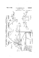
and arranged as to permit the same to rock on its axis, float up and down on its pivot, and fold b-ackwardly alongside the thresher part on another pivot. The rocking movement is balanced by a counterbalancing means located on the thresher part, but operable in its counterbalancing action entirely independent of said thresher. Therefore, as this counterbalance is carried` on the thresher part,V obviously the harvester part can be folded back for transport without in any way Adisturbing or interfering with said' counterbalance. Additional means isprovided ior'raising the platform up in a` vertical plane after it Reference should now'be made to the accompanying sheets of drawingsshowing an illustrative embodiment which this invention may -assume in practice'.` In the drawings the same characters of reference denote like parts throughout the views, and- Figure 1 is a plan view of so much of a'harvester thresher as' is necessary to a disclosure of this invention, and in this View the harvester part is shown in normal cutting position;
Figure 2 is a similar view but showing the harvester part in its horizontal `folded position;
Figure 3 is a rear view ofthe harvester thresher showing the harvester part in its vertically folded position; l V
Figure iis adetailnview of the frame construction;
Figure 5 is a side elevational detail View, showing the mounting of the counterbalancing means;
Figure 6 is a detail view of apart of the counterbalancing means;
Figure 7 is a similar detail view, partly in section, viewing a right angle part of the structure shown in Figure 5;
Figures 8, 9 and 10 are respectively detail views of the castings forming the two-way hinge `for the harvester support or axle; and,
Figures 11 and 12 are respectively plan and side detail views of the windlass used forraising the harvester part up vertically alongside the vthresher to its iinal folded position for transport..`
The thresher part of the harvester thresher of this invention embodies, as shown in Figures 1, 2 andB, a main frame I5 longitudinally disposed on a main aXle or thresher support I6 journaled left hand wheel I8 and forwardly thereof and above the same, the main frame l5 carries a super-frame structure 2o on which may be mounted an engine 2i generally indicated in Figures 1, 2 and 3, which engine vdrives the operative parts of the thresher and harvester, as is well known in this art.
In the drawings, and particularly Figure 3 it will be seen that the axle i6 has an extensionl 22 which extends a substantial distance grain'- wardly beyond the left hand wheel i8. Suitably keyed or otherwise made fast to the end of this extension 22 is a casting 23 depending below the extension 22 and forming a journal for a grainwardly extending, short stub shaft 24 said stub shaft being rockably mounted in the casting 23 for a purpose presently to appear, (see Figure 7). The stub shaft 2d is hollow and is made fast to the casting 23 by means of end plates 25 locked together by a bolt 2B. The construction'is such that free rockingmovement of the stub shaft 24 is permitted. t
The grainward end of the stub shaft 24 be-., yond the casting 23 is formed integrally with an upstanding arm 2l which, as clearly shown in `the drawings, isrbent or offset at its upper end in a stubbleward direction. The member 21 carries on its grainward face adjacent its lower end and substantially in line with the bolt 26 at its forward side a horizontally disposed, bifuroated socket 23 and at its back side, a vertically disposed, closed socket 29. The socket 29 is provided with a pin Sli, the upper and lower ends of which receivethe arms 3l of a bifurcated bracket 3l (seeY Figuresy 8 and 9), which bracket is formed with a centrally arranged, right ang'ularlyl extending bore 32. APassed through `the bore 32 is a horizontal pin 3S carried by a second .bifurcated casting 34 having arms 35 in which the pin 33 is carried, as shown in Figure 10. The casting 3d has made fast therein a harvester lsupport or axle 36.
r na pivot, which is carried in the vertical socket 29 on the back side of the arm 21.
Intermediately of its length the harvester laxle or support 3'6 is provided with a collar 3l which has pivotally `connected thereto, as shown in Figure 1, a normally diagonally and rearwardly extending brace bar 38, which is connected to the main frame i5, as shown at 38', and in this manner, during normal operation, the vertical pin Sllfused for folding is held inoperative although rocking movement of the support Sii with .the stub shaft 24 and aY vertical pivotal movement 42 is removed to permit the yoke 40 to swing freely on its pivot and caster.
The castings 34 and 39 on the support 36 each carry a forwardly extending bar 43, the forward ends of which support the usual rear angle bar 44 and the front Z-bar 45 upon which is carried a harvester header platform 36. Diagonal brace members il are provided for bracing a back Wall i8 for the header platform. Eye hooks 49 are provided on the back board 48 for a purpose later to appear.
The header platform llt, at the forward end of which is carried the usual grain cutting mechanism (not shown), must be raised and lowered so that the height of cut may be varied in accordance with the length of the grain encountered as the harvester thresher travels through the field. In the present embodiment this can be accomplished in any conventional way, such for example as by pulling up or pushing down on the Z-bar t5 by any suitable lever controlled mechanism well known in this art and, therefore, not shown herein. During the cutting operation, the parts are as in Figure 1 with the header platform extending forwardly of the support 3b. It will be noted that the stubbleward bar 43 is pivotally connected at 5! to a forward extension El of the casting 34, and similarly the stubbleward arm 43 is pivoted to the casting 39. Ledges or rests 52 are provided on these castings 34 and 39 for supporting the arms 43, as is well known in this art.v
Because Aof the great weight of the header platform 46, it would be very diiicult manually to raise and lower the same without some form of counterbalancing means. Accordingly, such means has been provided in the present invention, and the same will now be described. Attention is particularly directed to Figures 3, 5, 6 and '7. Above the axle extension 22 `of the thresher part, the main frame I5 and the casting 23 are provided with journals 5S and 54 in which is rockably journaled a rockshaft 55. The rockshaft 55 is provided with an upstanding arm 55, the upper end of which is provided with an elongated lslot 5l, the said arm being rockable with the shaft 55. The upper end of the arm 5@ is strengthened by a brace 58 lpivoted thereto and to the journal 54. It will be remembered that the arm 2l on the hollow stub shaft 24 extends upwardly and is bent in a stubbleward direction. The purpose of this will now be clear, for it can be seen that the upper end of this arm 2l is provided with a pin 59 on which is freely rotatable a roller which is fitted into the slot 5l of the adjacent arm 56 and is so held in that position by means of a nut and washer Si. The lower end of the arm 56, by means of a socketed casting E2, carries a rearwardly extending arm 63 of substantial length on the rear end of which is carried a heavy weight 64. Intermediately of its length, the arm 63 has formed thereon a collar 65, the lower end of which is provided with a shoe E6 and the upper end of which has connected thereto a brace rod 8l, the forward end of which is connected to the upper end of the arm 5E (see Figure 5). A second brace rod 6l extends from the casting E5 to the journal 54 on the rockshaft 55.
When the harvester is in its normal cutting position, as shown in Figure 1, it can now be seen that, if the platform is rocked downwardly, the support 36 will also rook forwardly on its horizontal axis and through the articulated connections described will rock the Vweighted arm 63 horizontal axis and the weighted arm 63 will move downwardly to assist elevation of the platform as will now be understood.y j
When the harvester part is folded rearwardly, as Vshown in Figure with the `platform still remaining in a horizontal plane, the Ymachine has been substantially narrowed in width to lassist transportation of the same through narrow places. i
It has been found desirable, however, additionally to narrow the width of this machine, and accordingly means has been provided for augmenting the folding action by moving theparts from `the position shown in Figure 2 tothe position shown in Figure 3. For this purpose a shaft 68 is suitably journaled transversely across the top off the separator housing it, the stubbleward end thereof being provided with a hand crank E9, as shown in Figure 3. The grainward end of the shaft E8 is formed with a worm gear lll, (see Figures 11 and l2) which meshes with a worm pinion 'Elon a shaft l2 suitably journaled in a bracket 13 carried on the separator housing.` i A winding drum 11i can be formed with the pinion l l or be `made fast to the shaft 12, which drum is provided witha cable l5 which is coupled with a hookl having legs with upturned ends engageable with the eyes 49 on the braces 41 heretofore' described. Thus it will be seen that rotation of the hand crank G9 will wind up the cable l5 and raise the bars 43 on their pivots 59' and thereby vertically swing up the entire header platform from its hor'- izontal position, additionally to narrow the overallwidth of the harvester thresherlfor' easier transportation through narrowplaces. As the superstructure 2G .and engine 2| are disposed far enough ahead on the main frame, the header platform when thus folded up in noway conflicts with those elements. v
In Figure 3 there is indicated what disposition is made of the harvester reel indicated-at 1l, and it will be seen that the same is merely'disconnected from its drivinggearing, notshoi/n,` and thus remains in its normal position with respect to the header. Of course, when the harvester part is folded, the weighted arm 63 performs no counter-balancing function and the shoe 66 carried thereby rests on the brace 38 which has been removed from its normal position at its stubbleward lend and made fast to another socket indicated at I8 on the stubbleward end of the thresher main frame, shown'in Figure 2. It is believed that the operation and use of this invention will be quite clear from the above detailed description and, therefore, only a brief description thereof will be made at this time, as it is thought that such a description should suflce.
In normal operation,` the header assumes the positionshown in Figure 1 with the grain wheel yoke 4i) locked securely to the casting 39; Vertical adjustments of the platform 43 are accomplished in any conventional manner,` and its rocking movements with its support 33 are counterbalanced by the weighted arm 63 throughthe connections between the arms 21 and 56. In this normal cutting position, the support is permitted a free rocking movement with the stub shaft 24 in the casting 23, and similarly the support 35 may rise and fall automatically to conform with irregularitiesin theiground because of theprovision of the horizontal pivot pin 33 for that purpose. A
When it is desirable to transport the harvester thresher through narrow places, the stubbleward end of the reel and platform will be disconnected as is conventional in folding machines of this type and the pin 42 is removed to free the yoke 4B from theY casting 39, so that the yoke and wheel 4| will swing around and caster freely. -The support 36, and with it the platform 43 can now easily be swung through a right angle tothe i rear about the vertical pin 3D to the position as shown in Figure 2 after first removing the stubbleward end of the diagonal brace pipe 38,as
will be understood. With the parts as shown in Figure the brace pipe 38 is made fast to the socket 18 and the weighted balance arm 63, by means of the shoe E3, comes to a position of rest on said brace 38. The wheel 4| is now in a position to function as a trailing casterwheel. This folding operation, it can'now be seen, has been accomplished without in any way disturbing the counterbalancing means.
By means of the shaft $8 andthe crank 69, and the winding drum operable thereby, it is a simple matter to swing vthe header supporting bars 43 vertically up-with the header to the position` i shown in Figure 3 and thereby materially lessen A the over-al1 width of the machine additionally. Y
It is to be understood, of course, `that Vthe mechanism herein shownis illustrative of one form which a harvester thresher constructed in accordance withthis invention may assume in practice and that the same is susceptible of a great many'modications in structure and that it is the intention to cover such changes as fall within `the vspirit and scope of thisinvention as indicated in the following claims.
What is claimed is:
l. In a harvester thresher, a thresher, a harvester connected thereto and normally extending laterally thereof, means adapting the harvester transversely thereof in a horizontal plane, meansv i adapting the harvester for folding back horizontally, means for then folding the harvester up vertically'alongside said thresher, and means for retaining therharvester in such folded position.
4. In a harvester thresher, a thresher, a supv port, a harvester connected to the support and pivotally connected to the thresher and normally disposed transversely of the thresher in a horizon- Vtal plane but f-oldable backwardly alongside the thresher, and means connected to the thresher at a point higher than the support for elevating i the harvester alongside the thresher to obtain additional clearance.
5. In a harvester thresher, a thresher, aharvester foldingly connected thereto whereby the same may be swung in a horizontal plane from its normal transverse cutting position to a position folded alongside the thresher, and a windlass and cable on the thresher for drawing the harvester to an elevated position alongside the thresher to obtain additional clearance. 6. In a harvester thresher, a thresher, a harvester connected thereto and normally disposed transversely thereof in a horizontal plane, counterbalancing means for the harvester, means to permit folding of the harvester back horizontally, and means to cause its elevation to raised position above its `cutting range alongside the thresher without disturbing said counterbalancing means.
'7. In combination, a thresher, a harvester platform extending transversely thereof, means adapting the platform for folding rearwardly, and neans for then folding the platform from the rearward position upwardly alongside said thresher. 8. In a harvester thresher, a thresher part, a harvester part including a platform, the platform being normally extended transversely of the thresher part for cutting position,;hinged connections between the harvester part and thresh'er part permitting the platform tobe swung through one plane within its cutting'range into a folded position alongside the thresher part to obtain clearance, means for enabling the platform to be moved from its folded position through another plane substantially above and out of its cutting l range to obtain additional clearance, and aA counterbalance means for the harvester, the above operations being performable without removing y said counterbalance means.
- its cutting range, and releasable'means for holding the platform in such normal position, of means connecting the harvester to the thresher for folding movement alongside the thresher upon release of said releasable means to obtain traveling clearance, supporting connections for the platform movable upwardly to carry said platform from its folded position to a position Vupwardly above its cutting range to obtain additional traveling clearance and a counterbalance means for the platform, said operations being performable without removing the counterbalance means.
vvl0. A machine comprising a thresher, a harvester axle, said axle connected to the thresher for folding to a longitudinal positionalongside thereof for traveling clearance, bars pivotally connected to the axle, a platform supported on the bars, said bars normally being substantially horizontally disposed to support the platform in cutting position, said bars being movable upwardly about their pivotal connection to a substantially vertical position to carry the platform into position obtaining additional clearance above its cuttingA range.
11. A machine embodying a thresher, a harvester comprising a platform normally located in a transverse cutting position at the side of the thresher, support means associated with the thresher and carrying the harvester, said support means with the harvester being f oldable from the transverse position to a position alongside the thresher to obtain travel clearance, means whereby the platform may be moved to another position higher than its cutting range to obtain additional clearance, and counterbalance means for the platform, the said clearance obtaining movements being performable without removing the counterbalance means.
' 12. In combination, a thresher, a normally transverse axle pivotally connected to the thresher, raisable supporting bars connected to the axle,
said bars being normally substantially horizontally disposed and carrying a harvester platform, means adapting the axle with the platform for folding rearwardly alongside the thresher, and means exerting a lifting force for then raising theplatform supporting bars to a substantially vertical position.
13. In combination, a thresher, a harvester platform extending transversely thereof, means adapting the platform for folding rearwardly, and means exerting a lifting force moving the platform upwardly and inwardly toward the thresher to locate said platform in a higher position than its cutting range.
14. In combination, a thresher, a harvester platform including tiltable supporting bars, said platform in normal position extending transversely of the thresher, means adapting the platform with the supporting bars for folding movement rearwardly, and means for then exerting a lifting force for tilting the supporting bars substantially vertically upwardly to move the platform to an elevated position.
l5. In a harvester thresher, the combination with a thresher part, of an axle carrying a harvester platform, said axle connected to the thresher part for folding movement rearwardly to a position alongside the thresher part through a horizontal arc of substantially ninety degrees,
and connections pivoted to the axle and carrying the platform, said connections being movable through a vertical arc of substantially ninety degrees kto raise the platform to another folded position.
16. In a harvester thresher, in combination, a thresher part, a harvester part including a platform, and a double set of Yflexible connections intermediate the platform and the thresher part permitting movement of the platform in two angular directions to obtain clearance of the platform to a position substantially above cutting range.
17. In a harvester thresher, in combination, a thresher part, a harvester part. including a platform, an axle, and bars supporting the platform and movable with the axle to carry the platform to a clearance position and movable relative to the axle tov impart additional clearance to the platform by locating the same in a position substantially above cutting range.
18. In a harvester thresher, in combination, a thresher part, a harvester part, an axle flexibly connected to the thresher part, a platform included in the harvester part, and supports between the axle and platform having a bodily movement with the axle and a movement of angularity with respect to the axle to obtain clearance by locating the platform in a position out of its cutting range.
19. In a harvester thresher, in combination, a thresher part, a harvester part including a'platform, connections intermediate the platform and thresher part permitting arelative movement of said parts in a plurality of angular directions obtaining traveling clearance for the platform above its cutting range, and counterbalance means for the platform, the said clearance movements being performable without removing the counterbalance means.
20. In a harvester thresher, a thresher, a F
means connected between the thresher and the harvester for elevating the platform to aposition above the cutting range to obtain additional transport clearance. f
21. In a harvester thresher, a thresher, a harvester foldingly connected thereto whereby the same may be swung in a horizontal plane from its normal transverse cutting position to a position i folded alongside the thresher, va flexible element carried by the thresher and connected to the har- `vesterfor drawing the harvester to an elevated travel clearance, a combination grain and caster wheel supporting the outer end of the harvester which wheel embodies means so that in the vcutting position of the harvester the wheel isadapted to be xed against castering and in the folded position of the harvester is adapted to be freed to permit it to caster, means enabling the harvester platform to be elevated to a position above` its cutting range to obtain additional travel clearance, and counterbalance means for the platform, said clearance obtaining movements being achieved without removing the counterbalance means.
23. A harvester thresher having a longitudinal thresher, a platform connected thereto for move- A ment from a normal transverse horizontal cutting position about two axes to a transport clearance position alongside the thresher to locate the same in a position higher than its cutting range, a support for the platform, anda combination grain and caster wheel for the support, said wheel in all positions of the platform `always being in supporting relation to the support, said wheel embodying means to enable the wheel to caster in the folded position of the platform and to be held against castering in the normal position of the platform.
24. In a harvester thresher, a longitudinal thresher, a harvester embodying a platform, means hingedly associating the harvester with the thresher to enable folding movement thereof from a normal transverse cutting position to a tion above its cutting range to obtain additional travel clearance.
25. In a harvester thresher, a longitudinal thresher, a harvester support hingedly associated with thei thresher and normally disposed in transverse relation to the thresher, line levers carried by the support, a platform carried by the line levers, said support with the parts carried thereby being foldable rearwardly and horizontally from the said normal position to a position longitudinally alongside the thresher to obtain transport clearance, means whereby the line levers may be tilted upwardly to elevate the platform toobtain additional transport clearance, and a wheel in permanent supporting relation to the outer end of said support.
26. In a harvester thresher, a longitudinal thresher, a harvester support hingedly associated with the thresher and normally disposed in transverse relation to the thresher, line levers carried by the support, a platform carried by the line levers, said support with the parts carried thereby being foldable rearwardly and horizontally from the said normal position to a position longitudinally alongside the thresher to obtain transport clearance, means whereby the line levers may be tilted upwardly to elevate the platform toy obtain additional transport clearance, and a wheel in permanent supportingrelation to the outer end of said support said wheel further having means associated therewith to lock the same against castering in the transverse position of the support, said means being releasable to enable the said wheel to caster when the support is in its longitudinal folded position.
2'7. In a harvester thresher, a longitudinal thresher, `a harvester support hingedly associated with the thresher and normally disposed in transverse relation to the thresher, line levers carried by the support, a platform carried bythe line levers, said support with the parts carried thereby being foldable rearwardly and horizontally from the said normal position to a position `longitudinally alongside the vthresher to obtain transport clearance, means whereby the line levers may be tilted upwardly to elevate the platform to obtain additional transport clearance, and a wheel in permanent supporting relation to the outer end of said support said wheel in the transverse position of the support being coaXially arranged therewith and including lock means to hold the wheel against castering in the transverse position of the support, said lock means being releasable to free the wheel for castering when the support is being folded and when said support is in the folded transport position.
' EDWARD A. JOHNSTON.
CLEMMA R. RANEY. ARNOLD E. W. JOHNSON.
Priority Applications (1)
| Application Number | Priority Date | Filing Date | Title |
|---|---|---|---|
| US674916A US2002205A (en) | 1926-10-14 | 1933-06-08 | Harvester thresher |
Applications Claiming Priority (2)
| Application Number | Priority Date | Filing Date | Title |
|---|---|---|---|
| US141449A US1948921A (en) | 1926-10-14 | 1926-10-14 | Harvester thresher |
| US674916A US2002205A (en) | 1926-10-14 | 1933-06-08 | Harvester thresher |
Publications (1)
| Publication Number | Publication Date |
|---|---|
| US2002205A true US2002205A (en) | 1935-05-21 |
Family
ID=26839132
Family Applications (1)
| Application Number | Title | Priority Date | Filing Date |
|---|---|---|---|
| US674916A Expired - Lifetime US2002205A (en) | 1926-10-14 | 1933-06-08 | Harvester thresher |
Country Status (1)
| Country | Link |
|---|---|
| US (1) | US2002205A (en) |
Cited By (1)
| Publication number | Priority date | Publication date | Assignee | Title |
|---|---|---|---|---|
| US2822812A (en) * | 1953-12-07 | 1958-02-11 | Edwards Delbert | Disk type grain thresher |
-
1933
- 1933-06-08 US US674916A patent/US2002205A/en not_active Expired - Lifetime
Cited By (1)
| Publication number | Priority date | Publication date | Assignee | Title |
|---|---|---|---|---|
| US2822812A (en) * | 1953-12-07 | 1958-02-11 | Edwards Delbert | Disk type grain thresher |
Similar Documents
| Publication | Publication Date | Title |
|---|---|---|
| US2227310A (en) | Basket-ball backstop apparatus | |
| US3574990A (en) | Support and linkage system for harvester platforms | |
| BR112021011659A2 (en) | COMBINED PLATFORM EQUIPPED WITH AN AUTOMATED PLATFORM TRANSPORT SYSTEM | |
| US3822534A (en) | Front mounted harvester | |
| US2922534A (en) | Drive-on lift trailer | |
| US2002205A (en) | Harvester thresher | |
| US1921233A (en) | Cable reel transporting vehicle | |
| US2286619A (en) | Wheel drag | |
| US2676719A (en) | Stacker and sweep-rake attachment for tractors | |
| US2235043A (en) | Steerable hand truck | |
| US1948921A (en) | Harvester thresher | |
| US2028332A (en) | Side delivery rake | |
| US2870555A (en) | Level control attachment for road graders | |
| US3995411A (en) | Oscillating mounting support for agricultural instrument | |
| US2151436A (en) | Sweep rake | |
| US2817943A (en) | Tilting, raising and lowering mechanism for windrow harvester platforms | |
| US1936630A (en) | Combination harvester-thresher | |
| US2040699A (en) | Harvester thresher | |
| US1672140A (en) | Land leveler | |
| US1894138A (en) | Harvester thresher | |
| US1945009A (en) | Harvester | |
| US1488510A (en) | Road planer | |
| US1123420A (en) | Grading-machine. | |
| US1564126A (en) | Scraper | |
| US1338200A (en) | Rotary-rod weeder |