US2002157A - Spring structure - Google Patents
Spring structure Download PDFInfo
- Publication number
- US2002157A US2002157A US640996A US64099632A US2002157A US 2002157 A US2002157 A US 2002157A US 640996 A US640996 A US 640996A US 64099632 A US64099632 A US 64099632A US 2002157 A US2002157 A US 2002157A
- Authority
- US
- United States
- Prior art keywords
- coils
- construction
- border
- suspended
- spring
- Prior art date
- Legal status (The legal status is an assumption and is not a legal conclusion. Google has not performed a legal analysis and makes no representation as to the accuracy of the status listed.)
- Expired - Lifetime
Links
- 238000010276 construction Methods 0.000 description 49
- 235000014676 Phragmites communis Nutrition 0.000 description 5
- 230000004048 modification Effects 0.000 description 5
- 238000012986 modification Methods 0.000 description 5
- 238000006073 displacement reaction Methods 0.000 description 4
- 239000000725 suspension Substances 0.000 description 3
- 239000011521 glass Substances 0.000 description 2
- 238000004519 manufacturing process Methods 0.000 description 2
- 238000009966 trimming Methods 0.000 description 2
- 150000001768 cations Chemical class 0.000 description 1
- 230000008030 elimination Effects 0.000 description 1
- 238000003379 elimination reaction Methods 0.000 description 1
- 239000004744 fabric Substances 0.000 description 1
- 239000000835 fiber Substances 0.000 description 1
- 230000009191 jumping Effects 0.000 description 1
- 210000002414 leg Anatomy 0.000 description 1
- 239000000463 material Substances 0.000 description 1
- 238000000034 method Methods 0.000 description 1
- 230000009467 reduction Effects 0.000 description 1
- 238000007665 sagging Methods 0.000 description 1
- 210000000689 upper leg Anatomy 0.000 description 1
Images


Classifications
-
- B—PERFORMING OPERATIONS; TRANSPORTING
- B60—VEHICLES IN GENERAL
- B60N—SEATS SPECIALLY ADAPTED FOR VEHICLES; VEHICLE PASSENGER ACCOMMODATION NOT OTHERWISE PROVIDED FOR
- B60N2/00—Seats specially adapted for vehicles; Arrangement or mounting of seats in vehicles
- B60N2/70—Upholstery springs ; Upholstery
- B60N2/7023—Coach-like constructions
- B60N2/7035—Cushions
- B60N2/7041—Fixation of covers and springs
Definitions
- One of the objects of this invention is to provide a spring construction of the suspended center type in which the usual center spring coils are entirely eliminated and rows of border coils are depended upon to furnish the so-called individual feel, particularly at the points at which the thigh of the legs and the shoulder blades are supported, while the majority of the weight of the occupant is supported upon a semi-rigid reticular surface resiliently suspended from the border coils in a manner permitting the entire construction to function as a unit.
- Another object of this invention is to provide a suspended central surface which will have no tendency to pocket during use and is of such a character as to permit the padding, employed during the trimming operation, to be directly supported thereupon, and will aid in retaining the same in the position originally applied thus eliminating bunching.
- a further object of this invention is to provide a suspended center which can be more economically fabricated than any type disclosed in my co-pending application above mentioned and which possesses riding qualities favorably comparable therewith.
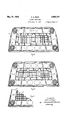
- Fig. 1 is a plan view of a suspended center type of spring construction embodying my improved type of supporting surface.
- Fig. 2 is a cross sectional view taken upon line 22 of Fig. 1.
- Figs. 3 and 4 are modified forms of my invention showing the reticulate supported surface divided into two and three sections, respectively.
- Fig. 5 is a further modification showing the reticulate supporting surface directly suspended from the border coils.
- Fig. 6 is a plan view of a modified embodiment of my invention especially adapted for seats having backs of slight overhang.
- Fig. 7 is a modification along lines similar to those shown in Fig. 6.
- Fig. 8 is a cross sectional view taken on line 8-8 of Fig. '7.
- my improved suspended center construction consists in the provision of upper and lower border frame members, preferably flexible, spaced apart a distance equal to the depth of the construction by a border of longitudinally compressible spring coils which may be of any well known construction.
- a semi-rigid central supporting surface is suspended in the plane of the upper frame from the border coils.
- porting frame is preferably indirectly suspended from the coils through resilient members such as helical springs, but may be directly secured to the top of the coils if desired.
- Figs. 1 and 2 a full seat construction which may be of any suitable type, but which is shown as having flexible upper and lower frames l-2 spaced in any well known manner by a row of border coils illustrated as being of the Marshall type.
- any other well known type of spring coil construction may be employed, such as barrel, cone, hour glass, single or double knotted, fabric encased or otherwise.
- the usual clips, stay wires, and braces may be employed to impart the necessary rigidity to the assembly of upper and lower frames and border spring coils.
- An inner border wire 4 is preferabl clipped The supto the top portion of each coil to provide additional rigidity to the border coils and at the same time to permit the suspended supporting surface to function with the assembly of border coils and frames substantially as a unit to eliminate any sharp line of relative defiecture during operation as will be hereinafter described.
- a semi-rigid supporting surface 5 is suspended within the border coils substantially in the plane of the upper frame I.
- I have shown a reticulate screen constituting the supporting surface.
- Such surfaces in order to come within the scope of the present invention must be characterized by the ability to present substantially a preformed supporting surface during operation, and will not be readily deflected inwardly sufliciently to take a permanent set during ordinary use to interrupt the proper contour of the construction.
- a supporting surface of the above character is especially advantageous in the seat construction of a vehicle.
- the particular supporting surface shown is constructed from l3 gage basic wire interwoven to form substantially 1 meshes. It is to be understood that these figures are given by way of example, only, and that the gage of material employed and the spacing of the same to provide the proper rigidity is within the province of the skilled artisan.
- the surface 5 is suspended from the border coils by a plurality of longitudinally extensible members preferably in the form of helical springs 6.
- the members 5 are afiixed to the border of the surface 5 and are preferably anchored to both the inner border frame 4 and top portion of the spring coils 3.
- Sufficient members 6 should be employed in the suspension of the surface to eliminate any sharp line of relative deflection between the suspended central supporting surface and the border assembly. It is essential that the suspended central supporting surface be suspended in the border assembly in a manner to accomplish the functioning of the entire construction substantially as a unitary resilient supporting surface.
- the padding may be directly supported upon the top of the construction without the necessity of the usual burlap supporting surface; (2) the padding will be slightly deflected into the interstices of the screen 5, and will thus be held in a definite position during use; (3) the semi-rigid central supporting surface will present an even, uniform surface to the bulk of the supporting weight of the occupant with the elimination of high or uneven pressure spots; (4) the weight of the construction has been materially reduced over conventional type of construction with decided reductions in cost of fabrication, while at the same time a construction which is at least equal in feel and riding qualities to any of the numerous modified Marshall" type of construction results.
- the suspended central supporting surface is divided into two sections designated
- This type of construction is especially adapted for front seats and backs of vehicles which are customarily constructed to receive two occupants.
- the border spring coils 9 are of hour glass type located between upper and inner frames l0ll in a manner which may be identical with that described with reference to Fig. 1.
- the surfaces 1-8 are preferably suspended as described with reference to the surface 5.
- Helical springs 12 extend between the inner opposed ends of the surfaces 1-8.
- Fig. 4 is shown a further modification of structure in which the suspended central supporting surface is divided into three sections I3l4-l5. This type of construction is especially adapted for rear seats and backs constructed to accommodate three persons.
- Fig. 5 illustrates a still further form of construction in which the cost of fabrication has been still further reduced by suspending the central supporting surface l6 directly from the top portion of the spring coils.
- the suspended supporting surface receives substantially its entire resiliency, transversely and longitudinally of the construction, directly from the border spring coils.
- the transverse resiliency of the top spiral portion of the coils is equal to a substantial degree to the resiliency of the helical springs 6 l2 employed in the construction herebefore described.
- Fig. 6 the structure shown in Fig. 1 has been modified by eliminating the helical spring from which the back side of the wire screen is suspended and securing the screen directly to 'the coils l8 and I9.
- This is of particular advantage when the suspended screen type of construction is being employed as a seat structure where the back is not of sufiicient depth and overhang to prevent the occupant from being supported upon the back edge of the suspended screen.
- the hinge action which takes place at the interconnection between the coils l8 and the screen 20 at l9 results in excellent riding qualities.
- borders three sides of the construction and is anchored at its ends to the top outer border frame at 22-23.
- coil springs 25 are supported upon lateral braces 26 located in the usual base frame carrying the tacking strip or trim rail.
- the upper portion of the coils 26 may be interwoven or otherwise secured to the screen 20.
- the coils 25 may be employed to advantage in any of the other constructions herein disclosed.
- the coils 25 merely support the screen and are in no the sup- In order to impart the necessary rigidity to the spring assembly it has been the universal practice to employ diagonal bracing members extending from one side of the upper outer border to the other side of the lower outer border.
- well known in the art, is provided with lateral horizontal braces 32. Braces 33 are clipped centrally of the braces 32 and extend to the upper border frame 34. The necessary rigidity and spacing of the upper border frame 35 is effected by brace members 36 clipped to the frame 36 constituting an overhang. The braces 36 are supported upon the frame member 38 to which the spring coils 28 are secured and anchored at the inner ends to the screen 21.
- Braces 39 may also be employed in a manner similar to the braces 36 to properly space the sides of the upper border frame 35.
- the foregoing described method of bracing is shown adapted to the embodiment in Fig. '7 only by way of example. Obviously, it may be just as advantageously employed in any of the other embodiments illustrated in the accompanying drawings.
- a spring construction the combination with a flexible upper border frame of wire, of a marginal row of spring coils clipped to and spaced along the inside of said frame, a central supporting surface having sufficient rigidity to maintain substantially a preformed contour during ordinary use, said surface supporting the entire load placed upon the central portion of the construction during use and being suspended from and in substantially the plane of the top portion of said coils, and resilient means for suspending said central surfaces, said means being spaced along the edges of said surface and being operatively connected to substantially all of said marginal row of coils, whereby the load supported by said surface is distributed uniformly along said upper frame.
- a seat construction for vehicles having a front and rear, upper and lower border frames, a continuous border of coils secured within and between said frames, a central supporting surface suspended in said upper frame from the front and side border coils, the back edge of said surface being disposed over the rear border coils.
Landscapes
- Engineering & Computer Science (AREA)
- Aviation & Aerospace Engineering (AREA)
- Transportation (AREA)
- Mechanical Engineering (AREA)
- Seats For Vehicles (AREA)
Description
y 1935- c s. REED 2,002,157
SPRING STRUCTURE Filed Nov. 3, 1932 3 Sheets-Sheet 1 -/n very far 4 Clair 3 Reed May 21 1935. c. s. REED SPRING STRUCTURE Filed Nov. :5, 1952 3 Sheets-Sheet 2 &w e I W; n a
Afformy May 21, 1935. c. s. REED 2,002,157
SPRING STRUCTURE Filed Nov. 3, 1932 '3 Sheets-Sheet 5 ln van for Patented May 21, 1935 UNITED STATES PATENT orrlcs SPRING STRUCTURE Clair 8. Reed,
Jackson,
Mlcln, aseignor to Reynolds Spring Company, Jackson, Micln, corporation of Delaware Application November 3, 1932, Serial No. 640,996
10 Claims.
5 cation filed September 6, 1932, which bears Serial No. 631,874, which matured into Patent No. 1,- 948,130 issued February 20, 1934.
Although the present invention, as in my prior application above mentioned, is in no sense limited to seat and back structures for vehicles,
the herein illustrated forms which my invention may take are particularly adapted for employment in vehicle bodies. For this reason the objects and advantages hereinafter disclosed will have specific reference to vehicle seats and bodies, but such objects and advantages are intended to extend to other types of constructions wherein any one of the desired characteristics of the vehicle back and seat would be advantageous.
As the desires and requirement of the trade, as well as the generic principles of operation of my improved spring construction, have been set forth at considerable length in my co-pending application, it is my intention to limit the discussion herein to objects and advantages of the particular species illustrated.
One of the objects of this invention is to provide a spring construction of the suspended center type in which the usual center spring coils are entirely eliminated and rows of border coils are depended upon to furnish the so-called individual feel, particularly at the points at which the thigh of the legs and the shoulder blades are supported, while the majority of the weight of the occupant is supported upon a semi-rigid reticular surface resiliently suspended from the border coils in a manner permitting the entire construction to function as a unit.
Another object of this invention is to provide a suspended central surface which will have no tendency to pocket during use and is of such a character as to permit the padding, employed during the trimming operation, to be directly supported thereupon, and will aid in retaining the same in the position originally applied thus eliminating bunching.
A further object of this invention is to provide a suspended center which can be more economically fabricated than any type disclosed in my co-pending application above mentioned and which possesses riding qualities favorably comparable therewith.
These and other objects and advantages will appear as the description proceeds. It is to be clearly understood, however, that I do not wish to be limited to the exact details set forth in the description and the drawings, but I intend to include as part of my invention all such changes and modifications as would occur to those skilled in the art and fall within the scope of the claims.
In the accompanying drawings wherein several forms which the present invention may take are shown for the purpose of illustration,
Fig. 1 is a plan view of a suspended center type of spring construction embodying my improved type of supporting surface.
Fig. 2 is a cross sectional view taken upon line 22 of Fig. 1.
Figs. 3 and 4 are modified forms of my invention showing the reticulate supported surface divided into two and three sections, respectively.
Fig. 5 is a further modification showing the reticulate supporting surface directly suspended from the border coils.
Fig. 6 is a plan view of a modified embodiment of my invention especially adapted for seats having backs of slight overhang.
Fig. 7 is a modification along lines similar to those shown in Fig. 6.
Fig. 8 is a cross sectional view taken on line 8-8 of Fig. '7.
Generally, my improved suspended center construction consists in the provision of upper and lower border frame members, preferably flexible, spaced apart a distance equal to the depth of the construction by a border of longitudinally compressible spring coils which may be of any well known construction. A semi-rigid central supporting surface is suspended in the plane of the upper frame from the border coils. porting frame is preferably indirectly suspended from the coils through resilient members such as helical springs, but may be directly secured to the top of the coils if desired.
Having specific reference to the forms of my invention herein disclosed for the purpose of illustration, in Figs. 1 and 2 is shown a full seat construction which may be of any suitable type, but which is shown as having flexible upper and lower frames l-2 spaced in any well known manner by a row of border coils illustrated as being of the Marshall type. Obviously, any other well known type of spring coil construction may be employed, such as barrel, cone, hour glass, single or double knotted, fabric encased or otherwise. The usual clips, stay wires, and braces may be employed to impart the necessary rigidity to the assembly of upper and lower frames and border spring coils.
An inner border wire 4 is preferabl clipped The supto the top portion of each coil to provide additional rigidity to the border coils and at the same time to permit the suspended supporting surface to function with the assembly of border coils and frames substantially as a unit to eliminate any sharp line of relative defiecture during operation as will be hereinafter described.
A semi-rigid supporting surface 5 is suspended within the border coils substantially in the plane of the upper frame I. In the preferred form herein illustrated, I have shown a reticulate screen constituting the supporting surface. Although this type has several decided advantages, it will be readily apparent that other types may be employed. Such surfaces, however, in order to come within the scope of the present invention must be characterized by the ability to present substantially a preformed supporting surface during operation, and will not be readily deflected inwardly sufliciently to take a permanent set during ordinary use to interrupt the proper contour of the construction. A supporting surface of the above character is especially advantageous in the seat construction of a vehicle. Concentrated deflection of any particular portion of a seat construction, such as results from the walking and jumping thereupon by children, has a decided tendency in conventional center coil constructions to permanently dislocate the proper position of the coils. Obviously, in my improved supporting center a concentrated deflection which is insufficient to permanently distort the surface will be distributed to a substantial portion of the construction.
The particular supporting surface shown is constructed from l3 gage basic wire interwoven to form substantially 1 meshes. It is to be understood that these figures are given by way of example, only, and that the gage of material employed and the spacing of the same to provide the proper rigidity is within the province of the skilled artisan.
As shown in Fig. 1, the surface 5 is suspended from the border coils by a plurality of longitudinally extensible members preferably in the form of helical springs 6. The members 5 are afiixed to the border of the surface 5 and are preferably anchored to both the inner border frame 4 and top portion of the spring coils 3. Sufficient members 6 should be employed in the suspension of the surface to eliminate any sharp line of relative deflection between the suspended central supporting surface and the border assembly. It is essential that the suspended central supporting surface be suspended in the border assembly in a manner to accomplish the functioning of the entire construction substantially as a unitary resilient supporting surface.
The above described spring structure presents the following advantages: (1) During the trimming operation the padding may be directly supported upon the top of the construction without the necessity of the usual burlap supporting surface; (2) the padding will be slightly deflected into the interstices of the screen 5, and will thus be held in a definite position during use; (3) the semi-rigid central supporting surface will present an even, uniform surface to the bulk of the supporting weight of the occupant with the elimination of high or uneven pressure spots; (4) the weight of the construction has been materially reduced over conventional type of construction with decided reductions in cost of fabrication, while at the same time a construction which is at least equal in feel and riding qualities to any of the numerous modified Marshall" type of construction results.
In the modification shown in Fig. 3, the suspended central supporting surface is divided into two sections designated |8. This type of construction is especially adapted for front seats and backs of vehicles which are customarily constructed to receive two occupants. As illustrated, the border spring coils 9 are of hour glass type located between upper and inner frames l0ll in a manner which may be identical with that described with reference to Fig. 1. The surfaces 1-8 are preferably suspended as described with reference to the surface 5. Helical springs 12 extend between the inner opposed ends of the surfaces 1-8.
In Fig. 4 is shown a further modification of structure in which the suspended central supporting surface is divided into three sections I3l4-l5. This type of construction is especially adapted for rear seats and backs constructed to accommodate three persons.
Although the construction shown in Figs. 3 and 4 necessitates a slight increase in cost of fabricaq tion over the construction shown in Figs. 1 and 2, the riding qualities are increased by providing a greater degree of individual action between sections of the construction. This is of particular advantage when persons of unequal weight are occupying the same seat.
Fig. 5 illustrates a still further form of construction in which the cost of fabrication has been still further reduced by suspending the central supporting surface l6 directly from the top portion of the spring coils. With this type of construction, the suspended supporting surface receives substantially its entire resiliency, transversely and longitudinally of the construction, directly from the border spring coils. The transverse resiliency of the top spiral portion of the coils is equal to a substantial degree to the resiliency of the helical springs 6 l2 employed in the construction herebefore described.
In Fig. 6 the structure shown in Fig. 1 has been modified by eliminating the helical spring from which the back side of the wire screen is suspended and securing the screen directly to 'the coils l8 and I9. This is of particular advantage when the suspended screen type of construction is being employed as a seat structure where the back is not of sufiicient depth and overhang to prevent the occupant from being supported upon the back edge of the suspended screen. By eliminating the helical spring on the back side and increasing the width of the screen a distance equal to the gap spanned by the back helical spring as shown in Fig. 1, this disadvantage is overcome. Furthermore, the hinge action which takes place at the interconnection between the coils l8 and the screen 20 at l9 results in excellent riding qualities. With this type of construction the inner border frame 2| borders three sides of the construction and is anchored at its ends to the top outer border frame at 22-23.
In order to prevent any sagging of the screen 20 out of the plane of the top of the coils I8 due to lengthening of the helical springs during excessive use, coil springs 25 are supported upon lateral braces 26 located in the usual base frame carrying the tacking strip or trim rail. The upper portion of the coils 26 may be interwoven or otherwise secured to the screen 20. Obviously, the coils 25 may be employed to advantage in any of the other constructions herein disclosed. The coils 25 merely support the screen and are in no the sup- In order to impart the necessary rigidity to the spring assembly it has been the universal practice to employ diagonal bracing members extending from one side of the upper outer border to the other side of the lower outer border. Such construction limits the amount of 'deflecture and results in a noisy action. With reference to the present invention, the employment of a semirigid suspended supporting surface has resulted in a radical departure from conventional bracing practice. As shown in Figs. 7 and 8, a fibre filled channel base frame 3|, well known in the art, is provided with lateral horizontal braces 32. Braces 33 are clipped centrally of the braces 32 and extend to the upper border frame 34. The necessary rigidity and spacing of the upper border frame 35 is effected by brace members 36 clipped to the frame 36 constituting an overhang. The braces 36 are supported upon the frame member 38 to which the spring coils 28 are secured and anchored at the inner ends to the screen 21. By passing the braces 36 over the frame member 38 a lever action supporting the overhanging of the frame 35 is eifected. Braces 39 may also be employed in a manner similar to the braces 36 to properly space the sides of the upper border frame 35. The foregoing described method of bracing is shown adapted to the embodiment in Fig. '7 only by way of example. Obviously, it may be just as advantageously employed in any of the other embodiments illustrated in the accompanying drawings.
Having thus described my invention, what I claim as new and desire to protect by Letters Patent is:
1. In a spring construction, the combination with a flexible upper border frame of wire, of a marginal row of spring coils clipped to and spaced along the inside of said frame, a central supporting surface having sufficient rigidity to maintain substantially a preformed contour during ordinary use, said surface supporting the entire load placed upon the central portion of the construction during use and being suspended from and in substantially the plane of the top portion of said coils, and resilient means for suspending said central surfaces, said means being spaced along the edges of said surface and being operatively connected to substantially all of said marginal row of coils, whereby the load supported by said surface is distributed uniformly along said upper frame.
2. In a spring construction, the combination with upper and lower border frames of which the former is of resilient wire, of a marginal row of spring coils spacing said frames being clipped to and uniformly spaced along the inside thereof, a central supporting reticular surface having sufficient rigidity to maintain substantially a preformed contour during ordinary use upon which pending said central surface comprising helical springs spaced along the edges of said surface and being operatively connected to substantially all of said marginal row of coils, the load supported -by said surface being uniformly distributed to said coils and sides of said upper frame whereby the transverse resiliency of the coils and upper frame is utilized in the suspension of said surface.
3. In a spring construction, the combination with a lower border frame, and flexible upper inner and outer borderframes of resilient wire, of a marginal row of relatively closely spaced spring coils spacing said upper and lower frames, said coils being located between said inner and outer frames and having opposite portions of the tops thereof clipped thereto, a central supporting reticular surface having sufficient rigidity to maintain substantially a preformed contour during ordinary use spaced inwardly from said inner frame upon which the upholstery is adapted to be directly supported and restrained against lateral displacement, helical springs spaced along the edges of said surface having one end connected thereto and the other end connected to said inner frame for suspending said surface in substantially the plane of the tops of said coils and upper frames, upon deflection of said surface the load supported thereby being uniformly distributed to the said coils and sides of said upper frames to deflect the same inwardly, whereby the transverse resiliency of the coils and sides of the upper frames is utilized in the suspension of said surface.
4. In a spring construction, the combination with an upper border frame of wire having a border of coils in spaced relation secured thereto; of a central supporting reticular surface upon which the upholstery padding is adapted to be directly supported and restrained against lateral displacement, having sufficient rigidity to maintain substantially a preformed contour during ordinary use, suspended from and in substantially the plane of the top portion of said coils; said surface being disposed substantially normal of the longitudinal axes of said coils and supporting the entire load placed upon the central portion of the construction.
5. In a spring construction, the combination with an upper border frame of wire having a border of coils in spaced relation secured thereto; of a woven wire central supporting surface upon which the upholstery padding is adapted to be directly supported and restrained against lateral displacement, having sufficient rigidity to maintain substantially a preformed contour during ordinary use, suspended from and in substantially the plane of the top portion of said coils; said surface being disposed substantially normal of the longitudinal axes of said coils and supporting the entire load placed upon the central portion of the construction.
6. In a spring construction, the combination with upper and lower border frames; of a border of coils secured within and between said frames; a central supporting reticulate surface having sufficient rigidity to maintain substantially a preformed contour during ordinary use upon which the upholstery padding is adapted to be directly supported and restrained against lateral displacement; an inner border frame connected to the top portion of certain of said coils, resilient means suspending said surface from said inner frame, said surface being disposed substantially normal of the longitudinal axes of said coils, said means being spaced along the sides of said frame for uni-- formly distributing the load supported by sai surface to said inner frame and coils.
7. In a spring construction, the combination with upper and lower border frames; of a border of coils secured within and between said frames; a plurality of central supporting surfaces, having suflicient rigidity to maintain substantially a preformed contour during ordinary use, resiliently suspended from and in substantially the plane of the top portion of said coils; resilient means connecting the opposed ends of said surfaces to each other; said surfaces being disposed substantially normal of the longitudinal axes of said coils.
8. In a seat construction for vehicles, having a front and rear, upper and lower border frames, a continuous border of coils secured within and between said frames, a central supporting surface suspended in said upper frame from the front and side border coils, the back edge of said surface being disposed over the rear border coils.
9. In a seat construction for vehicles, upper and lower border frames, a border of coils secured within and between said frames, 9, central supporting surface suspended in the plane of the upper frame, said surface being suspended indirectly through resilient means from said coils in the front portion of said construction and directly suspended from said coils in the rear portion.
10. In a spring construction, the combination with upper and lower border frames; of a border of coils secured within and between said frames; a central supporting surface suspended in the plane of said upper frame; a base frame supporting said lower frame having lateral braces; bracing members secured centrally of said lateral braces extending to one side of the upper frame; and additional bracing members secured to the other side of said upper frame in the plane thereof and having one end anchored to said surface.
CLAIR. S. REED.
Priority Applications (1)
| Application Number | Priority Date | Filing Date | Title |
|---|---|---|---|
| US640996A US2002157A (en) | 1932-11-03 | 1932-11-03 | Spring structure |
Applications Claiming Priority (1)
| Application Number | Priority Date | Filing Date | Title |
|---|---|---|---|
| US640996A US2002157A (en) | 1932-11-03 | 1932-11-03 | Spring structure |
Publications (1)
| Publication Number | Publication Date |
|---|---|
| US2002157A true US2002157A (en) | 1935-05-21 |
Family
ID=24570509
Family Applications (1)
| Application Number | Title | Priority Date | Filing Date |
|---|---|---|---|
| US640996A Expired - Lifetime US2002157A (en) | 1932-11-03 | 1932-11-03 | Spring structure |
Country Status (1)
| Country | Link |
|---|---|
| US (1) | US2002157A (en) |
Cited By (7)
| Publication number | Priority date | Publication date | Assignee | Title |
|---|---|---|---|---|
| US2596196A (en) * | 1945-07-23 | 1952-05-13 | L A Young Spring & Wire Corp | Spring structure |
| US2680475A (en) * | 1950-06-03 | 1954-06-08 | Chrysler Corp | Spring seat construction |
| US2695657A (en) * | 1948-08-10 | 1954-11-30 | L A Young Spring & Wire Corp | Spring cushion structure |
| WO1990011710A1 (en) * | 1989-04-10 | 1990-10-18 | Perry Leroy R Jr | Auxiliary frame and grid and interaction with mattress periphery |
| US5518226A (en) * | 1994-04-13 | 1996-05-21 | Bauhaus Usa, Inc. | Spring seating support system |
| WO2003063652A1 (en) * | 2002-01-29 | 2003-08-07 | Mattress Development Company Of Delaware, Llc | Mattress structure with an improved lumbar zone |
| US7640611B1 (en) | 2005-01-25 | 2010-01-05 | Kluft Earl S | Mattress design |
-
1932
- 1932-11-03 US US640996A patent/US2002157A/en not_active Expired - Lifetime
Cited By (14)
| Publication number | Priority date | Publication date | Assignee | Title |
|---|---|---|---|---|
| US2596196A (en) * | 1945-07-23 | 1952-05-13 | L A Young Spring & Wire Corp | Spring structure |
| US2695657A (en) * | 1948-08-10 | 1954-11-30 | L A Young Spring & Wire Corp | Spring cushion structure |
| US2680475A (en) * | 1950-06-03 | 1954-06-08 | Chrysler Corp | Spring seat construction |
| WO1990011710A1 (en) * | 1989-04-10 | 1990-10-18 | Perry Leroy R Jr | Auxiliary frame and grid and interaction with mattress periphery |
| US5027459A (en) * | 1989-04-10 | 1991-07-02 | Perry Jr Leroy R | Auxiliary frame and grid and interaction with mattress periphery |
| US5518226A (en) * | 1994-04-13 | 1996-05-21 | Bauhaus Usa, Inc. | Spring seating support system |
| WO2003063652A1 (en) * | 2002-01-29 | 2003-08-07 | Mattress Development Company Of Delaware, Llc | Mattress structure with an improved lumbar zone |
| US20050166329A1 (en) * | 2002-01-29 | 2005-08-04 | Carlitz Stuart S. | Mattress structure with an improved lumbar zone |
| US6996866B2 (en) | 2002-01-29 | 2006-02-14 | Mattress Development Company | Mattress structure with an improved lumbar zone |
| US20060080783A1 (en) * | 2002-01-29 | 2006-04-20 | Carlitz Stuart S | Mattress structure with an improved lumbar zone |
| US7181796B2 (en) * | 2002-01-29 | 2007-02-27 | Mattress Development Company | Mattress structure with an improved lumbar zone |
| US7640611B1 (en) | 2005-01-25 | 2010-01-05 | Kluft Earl S | Mattress design |
| US20100115703A1 (en) * | 2005-01-25 | 2010-05-13 | Kluft Earl S | Mattress design |
| US7917980B2 (en) | 2005-01-25 | 2011-04-05 | Kluft Earl S | Mattress design |
Similar Documents
| Publication | Publication Date | Title |
|---|---|---|
| US3639002A (en) | Seat construction | |
| US2231346A (en) | Seat construction | |
| US2893476A (en) | Seat construction | |
| US2002157A (en) | Spring structure | |
| US2265251A (en) | Spring cushion construction | |
| US2719578A (en) | Seating spring construction | |
| US2214136A (en) | Spring construction | |
| US2185036A (en) | Seat | |
| US3071413A (en) | Seat construction | |
| US2071974A (en) | Chair back | |
| US2080607A (en) | Chair | |
| US2186548A (en) | Spring assembly for upholstery | |
| US2293563A (en) | Cushion construction | |
| US2253914A (en) | Seat cushion | |
| US2133611A (en) | Wire spring for cushioned seats of vehicles | |
| US2936823A (en) | Seating construction | |
| US1948130A (en) | Spring structure | |
| US3127220A (en) | Seat cusfflon and spring construction | |
| US2469216A (en) | Suspension spring seat | |
| US2040780A (en) | Spring structure | |
| US2675065A (en) | Spring cushion structure | |
| US2313130A (en) | Floating motion cushion for vehicles, furniture, and the like | |
| US1993530A (en) | Theater seat | |
| US2149350A (en) | Cushion construction | |
| US2284108A (en) | Spring seat |