US20020184889A1 - Fastening a CMC combustion chamber in a turbomachine using the dilution holes - Google Patents
Fastening a CMC combustion chamber in a turbomachine using the dilution holes Download PDFInfo
- Publication number
- US20020184889A1 US20020184889A1 US10/161,782 US16178202A US2002184889A1 US 20020184889 A1 US20020184889 A1 US 20020184889A1 US 16178202 A US16178202 A US 16178202A US 2002184889 A1 US2002184889 A1 US 2002184889A1
- Authority
- US
- United States
- Prior art keywords
- combustion chamber
- tongues
- metal
- turbomachine according
- shells
- Prior art date
- Legal status (The legal status is an assumption and is not a legal conclusion. Google has not performed a legal analysis and makes no representation as to the accuracy of the status listed.)
- Granted
Links
- 238000002485 combustion reaction Methods 0.000 title claims abstract description 54
- 238000010790 dilution Methods 0.000 title claims abstract description 9
- 239000012895 dilution Substances 0.000 title claims abstract description 9
- 210000002105 tongue Anatomy 0.000 claims abstract description 45
- 239000002184 metal Substances 0.000 claims abstract description 33
- 239000002131 composite material Substances 0.000 claims abstract description 18
- 239000007769 metal material Substances 0.000 claims abstract description 11
- 238000002347 injection Methods 0.000 claims abstract description 10
- 239000007924 injection Substances 0.000 claims abstract description 10
- 239000000446 fuel Substances 0.000 claims abstract description 6
- 239000007800 oxidant agent Substances 0.000 claims description 19
- 238000005219 brazing Methods 0.000 claims description 5
- 238000006073 displacement reaction Methods 0.000 claims description 4
- 238000002788 crimping Methods 0.000 claims description 3
- 238000003825 pressing Methods 0.000 claims description 3
- 238000003466 welding Methods 0.000 claims description 3
- 238000007789 sealing Methods 0.000 claims 2
- 239000011153 ceramic matrix composite Substances 0.000 description 5
- 238000011144 upstream manufacturing Methods 0.000 description 4
- 239000000463 material Substances 0.000 description 3
- 238000009792 diffusion process Methods 0.000 description 2
- OKTJSMMVPCPJKN-UHFFFAOYSA-N Carbon Chemical compound [C] OKTJSMMVPCPJKN-UHFFFAOYSA-N 0.000 description 1
- 229910052799 carbon Inorganic materials 0.000 description 1
- 238000005260 corrosion Methods 0.000 description 1
- 230000007797 corrosion Effects 0.000 description 1
- 239000002905 metal composite material Substances 0.000 description 1
- 238000000034 method Methods 0.000 description 1
- 239000002994 raw material Substances 0.000 description 1
- 230000000284 resting effect Effects 0.000 description 1
- 235000002020 sage Nutrition 0.000 description 1
Images


Classifications
-
- F—MECHANICAL ENGINEERING; LIGHTING; HEATING; WEAPONS; BLASTING
- F23—COMBUSTION APPARATUS; COMBUSTION PROCESSES
- F23R—GENERATING COMBUSTION PRODUCTS OF HIGH PRESSURE OR HIGH VELOCITY, e.g. GAS-TURBINE COMBUSTION CHAMBERS
- F23R3/00—Continuous combustion chambers using liquid or gaseous fuel
- F23R3/02—Continuous combustion chambers using liquid or gaseous fuel characterised by the air-flow or gas-flow configuration
- F23R3/04—Air inlet arrangements
- F23R3/06—Arrangement of apertures along the flame tube
-
- F—MECHANICAL ENGINEERING; LIGHTING; HEATING; WEAPONS; BLASTING
- F23—COMBUSTION APPARATUS; COMBUSTION PROCESSES
- F23R—GENERATING COMBUSTION PRODUCTS OF HIGH PRESSURE OR HIGH VELOCITY, e.g. GAS-TURBINE COMBUSTION CHAMBERS
- F23R3/00—Continuous combustion chambers using liquid or gaseous fuel
- F23R3/007—Continuous combustion chambers using liquid or gaseous fuel constructed mainly of ceramic components
-
- F—MECHANICAL ENGINEERING; LIGHTING; HEATING; WEAPONS; BLASTING
- F23—COMBUSTION APPARATUS; COMBUSTION PROCESSES
- F23R—GENERATING COMBUSTION PRODUCTS OF HIGH PRESSURE OR HIGH VELOCITY, e.g. GAS-TURBINE COMBUSTION CHAMBERS
- F23R3/00—Continuous combustion chambers using liquid or gaseous fuel
- F23R3/42—Continuous combustion chambers using liquid or gaseous fuel characterised by the arrangement or form of the flame tubes or combustion chambers
- F23R3/60—Support structures; Attaching or mounting means
-
- F—MECHANICAL ENGINEERING; LIGHTING; HEATING; WEAPONS; BLASTING
- F05—INDEXING SCHEMES RELATING TO ENGINES OR PUMPS IN VARIOUS SUBCLASSES OF CLASSES F01-F04
- F05B—INDEXING SCHEME RELATING TO WIND, SPRING, WEIGHT, INERTIA OR LIKE MOTORS, TO MACHINES OR ENGINES FOR LIQUIDS COVERED BY SUBCLASSES F03B, F03D AND F03G
- F05B2230/00—Manufacture
- F05B2230/60—Assembly methods
- F05B2230/604—Assembly methods using positioning or alignment devices for aligning or centering, e.g. pins
- F05B2230/606—Assembly methods using positioning or alignment devices for aligning or centering, e.g. pins using maintaining alignment while permitting differential dilatation
-
- Y—GENERAL TAGGING OF NEW TECHNOLOGICAL DEVELOPMENTS; GENERAL TAGGING OF CROSS-SECTIONAL TECHNOLOGIES SPANNING OVER SEVERAL SECTIONS OF THE IPC; TECHNICAL SUBJECTS COVERED BY FORMER USPC CROSS-REFERENCE ART COLLECTIONS [XRACs] AND DIGESTS
- Y02—TECHNOLOGIES OR APPLICATIONS FOR MITIGATION OR ADAPTATION AGAINST CLIMATE CHANGE
- Y02T—CLIMATE CHANGE MITIGATION TECHNOLOGIES RELATED TO TRANSPORTATION
- Y02T50/00—Aeronautics or air transport
- Y02T50/60—Efficient propulsion technologies, e.g. for aircraft
Definitions
- the present invention relates to the specific field of turbomachines, and more particularly it relates to the problem posed by mounting a combustion chamber made of ceramic matrix composite (CMC) type material in the metal chamber casings of a turbomachine.
- CMC ceramic matrix composite
- the high pressure turbine (HPT) and in particular its inlet nozzle, the combustion chamber, and the inner and outer shells (or casings) of said chamber are all made of the same material, generally a metal.
- HPT high pressure turbine
- the combustion chamber, and the inner and outer shells (or casings) of said chamber are all made of the same material, generally a metal.
- metal combustion chamber turns out to be entirely inappropriate from a thermal point of view and it is necessary to use a chamber based on high temperature composite materials of the CMC type.
- the difficulties of working such materials and their raw materials costs mean that their use is generally restricted to the combustion chamber itself, with the inlet nozzle of the high pressure turbine and the inner and outer shells containing the chamber then continuing to be made more conventionally out of metal materials.
- metal materials and composite materials have coefficients of thermal expansion that are very different. This gives rise to particularly severe problems of connection with the inner and outer shells and at the interface with the inlet nozzle to the high pressure turbine.
- the present invention mitigates those drawbacks by proposing a mount for the combustion chamber within the casings, which mount has the ability to absorb the displacements induced by the different expansion coefficients of these parts.
- Another object of the invention is to propose a mount which makes best use of the existing characteristics of the combustion chamber.
- a turbomachine comprising inner and outer annular shells of metal material containing, in a gas flow direction F: a fuel injection assembly; an annular combustion chamber of composite material having a longitudinal axis and a plurality of oxidizer feed orifices; and an annular nozzle of metal material having fixed blades and forming the inlet stage of a high pressure turbine, wherein said combustion chamber of composite material is held in position between said inner and outer annular metal shells by a plurality of flexible metal tongues, first ends of said tongues being interconnected by respective metal rings fixed securely to each of said inner and outer annular metal shells by first fixing means, and second ends of said tongues being fixed securely to said composite material combustion chamber via at least a fraction of said oxidizer feed orifices by second fixing means, the flexibility of said fixing tongues serving, at high temperatures, to accommodate free displacement in radial and axial directions between said composite material combustion chamber and said inner and outer annular metal shells.
- the oxidizer feed orifices are
- the flexible fixing tongues are made of a metal material and the first fixing means are preferably constituted by a plurality of bolts.
- said first ends of the tongues are connected by brazing or welding to said rings or else they are formed integrally therewith.
- each ring is preferably mounted between connecting flanges between said two portions of said annular metal shell.
- each of said second fixing means comprising a collar inserted in the oxidizer feed orifice of said combustion chamber and is crimped to the second ends of the tongues so as to ensure that said tongues are held against the combustion chamber once the crimping has been achieved.
- said second fixing means comprise a plurality of inserts each comprising two coaxial parts that are fixed one on the other, comprising firstly a collar pressed against a side wall of the combustion chamber and secondly a ring surrounding said collar and pressing the second ends of the tongues against said side wall.
- said tongues have respective openings formed close to their second ends in order to improve the feed of oxidizer to said feed orifices.
- the stream of gas is preferably sealed between said combustion chamber and said nozzle by a circular “spring-blade” type gasket bearing directly against a downstream end of said combustion chamber which forms a bearing plane for said circular gasket.
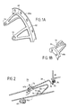
- FIG. 1 is an axial half-section of a central zone of a turbomachine constituting a first embodiment of the invention
- FIGS. 1A and 1B show examples respectively of a flexible fixing tongue for the outer wall and for the inner wall of the combustion chamber
- FIG. 2 is a view showing a portion of FIG. 1 on a larger scale using an alternative connection configuration
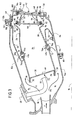
- FIG. 3 is a diagrammatic axial half-section of a central zone of a turbomachine constituting a second embodiment of the invention.
- FIGS. 1 and 3 are axial half-sections of a central portion of a turbojet or a turboprop (referred to generically in the description below as a “turbomachine”), comprising:
- an outer annular shell made up of two metal portions 12 a , 12 b about a longitudinal axis 10 ;
- a coaxial inner annular shell (or casing) likewise made up of two metal portions 14 a , 14 b ;
- this space 16 contains firstly an injection assembly comprising a plurality of injection systems 20 regularly distributed around the duct 18 and each comprising a fuel injection nozzle 22 fixed on an upstream portion 12 a of the annular outer shell (in order to simplify the drawings, the mixer and the deflector associated with each injection nozzle have been omitted), followed by a combustion chamber 24 of composite material, e.g. of the CMC type, comprising an outer axially-extending side wall 26 and an inner axially-extending side wall 28 , both side walls being coaxial about the axis 10 , and a transversely-extending end wall 30 likewise made of a high temperature composite material of the CMC type or the like (e.g.
- said end wall having margins 32 and 34 fixed to the upstream ends 36 , 38 of the side walls 26 , 28 , e.g. by flat-headed refractory or metal bolts, said end wall 30 being provided with through orifices 40 for enabling fuel and a portion of the oxidizer to be injected into the combustion chamber 24 , and the side walls further including a plurality of oxidizer feed orifices 41 a , 41 b , and finally an annular nozzle 42 of metal material forming an inlet stage for a high pressure turbine (not shown) and conventionally comprising a plurality of fixed blades 44 mounted between an outer circular platform 46 and an inner circular platform 48 .
- the nozzle is fixed to a downstream portion 14 b of the inner annular shell of the turbomachine via first releasable fixing means, preferably constituted by a plurality of bolts 50 , while also resting against support means 49 secured to the outer annular shell of the turbomachine.
- the compressed oxidizer leaving the diffusion duct 18 is split into a plurality of flows including at least flows F 1 , F 2 flowing on either side of the combustion chamber 24 (together with a central flow F 3 that mixes with the fuel in order to be injected into the chamber).
- Each oxidizer flow F 1 , F 2 is subsequently inserted into the chamber via the feed orifices 41 a , 41 b , or else is directed to through orifices 54 , 56 provided through the outer and inner metal platforms 46 and 48 of the nozzle 42 to cool the fixed blades 44 of the nozzle at the inlet to the high pressure turbine rotor.
- the combustion chamber 24 which has a thermal expansion coefficient that is very different from that of the other parts making up the turbomachine which are themselves made of metal, is held securely in position between the inner and outer annular shells by a plurality of flexible tongues 58 , 60 that are regularly distributed around the combustion chamber.
- a first fraction of these fixing tongues (see the tongue referenced 58 ) is mounted between the outer annular shell 12 a , 12 b and the outer side wall 26 of the combustion chamber, and a second fraction of the tongues (such as the tongue 60 ) is mounted between the inner annular shell 14 a , 14 b and the inner side wall 28 of the combustion chamber.
- each flexible fixing tongue of metal material is substantially triangular in shape, being brazed or welded via its base 62 ; 64 to a metal ring 66 a , 66 b or that is formed integrally therewith.
- the ring is secured to one or the other of the outer or inner metal annular shells 12 or 14 by first fixing means 52 , 68 .
- the vertex 70 ; 72 of the tongue is secured to the outer or inner side walls 26 or 28 of the composite material combustion chamber via all or some of the oxidizer feed orifices 41 a , 41 b using second fixing means 74 , 76 .
- oxidizer feed orifices can be dilution holes and/or primary holes for feeding the combustion chamber with air (particularly in a so-called “short” combustion chamber configuration).
- the number of tongues is proportional to the number of these holes and this number is generally equal to the number of injection nozzles or equal to a multiple of said number (for example 60 tongues will be used if the chamber has 20 injection nozzles each having three dilution holes).
- FIG. 1 shows a first embodiment of the invention in which the vertices 70 , 72 forming second ends of the tongues are fixed respectively on the outer and inner side walls 26 and 28 of the combustion chamber by being crimped by means of collars 74 , 76 inserted from the hearth side of the combustion chamber thorough respective oxidizer feed orifices 41 a , 41 b and serving to hold the tongue against the combustion chamber wall once crimping has been performed.
- the real diameter of the feed orifice is matched by the collar whose outer edges (on the hearth side of the chamber) are rounded so as to avoid catching flames.
- the bases 62 , 64 forming first ends of the tongues as interconnected by the ring 66 a , 66 b are preferably held between existing flanges for connecting together the upstream and downstream portions of the inner and outer annular shells 14 a , 14 b and 12 a , 12 b , and are held securely by fixing means 52 , 68 , preferably of the bolt type.
- the tongues 60 for fixing to the inner annular shell 14 b are in the form of thin metal strips (of optionally constant width) each having a first end welded to a metal ring 75 which is not clamped between flanges but instead is fixed directly to the downstream portion 14 b of the inner annular shell by fixing means 77 , e.g. of the bolt type.
- the second ends of these tongues are constituted by metal pieces 79 .
- the gas stream is sealed between the combustion chamber 24 and the nozzle 42 by providing circular “spring-blade” gaskets 80 , 82 mounted in respective grooves 84 , 86 in the outer and inner platforms 46 , 48 of the nozzle and bearing directly against downstream ends 88 , 90 of the combustion chamber forming bearing planes for said gasket.
- Each gasket is pressed against the corresponding end of the chamber by a resilient element of the circular spring-blade type 92 , 94 which is fixed to the nozzle.
- the gasket need not bear directly against the downstream end of the combustion chamber but instead bears against a ring of composite material fitted to said downstream end, conventionally by brazing or less conventionally by an implanting technique known by the term “pin'sage”.
- the flow of gas between the combustion chamber and the turbine is sealed firstly by an omega type circular gasket 96 mounted in a circular groove 98 in a flange of the inner annular shell 14 in direct contact with the inner circular platform 48 of the nozzle, and secondly by another circular gasket 100 , of the “spring-blade” type mounted in a circular groove 102 of the outer circular platform 46 of the nozzle having one end in direct contact with a circular rim 104 of the downstream portion 12 b of the outer annular shell.
- the second ends of the tongues 70 , 72 are fixed respectively to the outer and inner side walls 26 , 28 of the combustion chamber via inserts each comprising two coaxial portions fixed to each other (advantageously by brazing or welding), one comprising a collar 74 a , 76 a pressed against the hearth side of the wall and the other in the form of a ring 74 b , 76 b surrounding the collar and pressing the eyelet-forming second end of the tongue against the wall.
- the real diameter of the dilution hole or of the primary hole is taken up by the collar whose outer edges are rounded so as to avoid catching flames.
- the tongue 58 can have an opening 58 a formed close to the second end 70 of the tongue in register with the injection orifice 41 a so as to make it easier to feed after assembly.
- the first ends of this tongue are no longer welded to a ring mounted between flanges (as shown in FIG. 1) but they are brazed to keying means 106 secured to the outer annular shell 12 .
- the flexibility of the fixing tongues serves to accommodate the thermal expansion difference that appears at high temperatures between the composite material combustion chamber and the annular metal shells, while ensuring that the combustion chamber is properly held and positioned.
- the use of oxidizer feed orifices as anchor points for these tongues facilitates assembly and minimizes bulk generally.
Landscapes
- Engineering & Computer Science (AREA)
- Chemical & Material Sciences (AREA)
- Combustion & Propulsion (AREA)
- Mechanical Engineering (AREA)
- General Engineering & Computer Science (AREA)
- Ceramic Engineering (AREA)
- Turbine Rotor Nozzle Sealing (AREA)
- Gasket Seals (AREA)
Abstract
Description
- The present invention relates to the specific field of turbomachines, and more particularly it relates to the problem posed by mounting a combustion chamber made of ceramic matrix composite (CMC) type material in the metal chamber casings of a turbomachine.
- Conventionally, in a turbojet or a turboprop, the high pressure turbine (HPT) and in particular its inlet nozzle, the combustion chamber, and the inner and outer shells (or casings) of said chamber are all made of the same material, generally a metal. Nevertheless, under certain particular conditions of use, implementing very high combustion temperatures, using a metal combustion chamber turns out to be entirely inappropriate from a thermal point of view and it is necessary to use a chamber based on high temperature composite materials of the CMC type. However, the difficulties of working such materials and their raw materials costs mean that their use is generally restricted to the combustion chamber itself, with the inlet nozzle of the high pressure turbine and the inner and outer shells containing the chamber then continuing to be made more conventionally out of metal materials. Unfortunately, metal materials and composite materials have coefficients of thermal expansion that are very different. This gives rise to particularly severe problems of connection with the inner and outer shells and at the interface with the inlet nozzle to the high pressure turbine.
- The present invention mitigates those drawbacks by proposing a mount for the combustion chamber within the casings, which mount has the ability to absorb the displacements induced by the different expansion coefficients of these parts. Another object of the invention is to propose a mount which makes best use of the existing characteristics of the combustion chamber.
- These objects are achieved by a turbomachine comprising inner and outer annular shells of metal material containing, in a gas flow direction F: a fuel injection assembly; an annular combustion chamber of composite material having a longitudinal axis and a plurality of oxidizer feed orifices; and an annular nozzle of metal material having fixed blades and forming the inlet stage of a high pressure turbine, wherein said combustion chamber of composite material is held in position between said inner and outer annular metal shells by a plurality of flexible metal tongues, first ends of said tongues being interconnected by respective metal rings fixed securely to each of said inner and outer annular metal shells by first fixing means, and second ends of said tongues being fixed securely to said composite material combustion chamber via at least a fraction of said oxidizer feed orifices by second fixing means, the flexibility of said fixing tongues serving, at high temperatures, to accommodate free displacement in radial and axial directions between said composite material combustion chamber and said inner and outer annular metal shells. The oxidizer feed orifices are constituted by holes for feeding air to a primary zone and/or a dilution zone of said combustion chamber.
- With this particular fixed connection structure, the various kinds of wear due to contact corrosion in prior art systems can be avoided. Using the primary holes or the dilution holes (depending on the intended chamber configuration) as anchor points also serves to simplify the connection considerably and to reduce the size thereof. In addition, the presence of flexible tongues taking the place of traditional flanges makes it possible to achieve an appreciable weight saving. Because of their flexibility, these tongues make it easy to accommodate the expansion difference that appears at high temperatures between metal parts and composite parts (by accommodating the displacements due to expansion) while continuing to hold the combustion chamber and keep it properly centered within the annular shells.
- The flexible fixing tongues are made of a metal material and the first fixing means are preferably constituted by a plurality of bolts.
- In one possible embodiment, said first ends of the tongues are connected by brazing or welding to said rings or else they are formed integrally therewith. When said annular metal shell is made up of two portions, each ring is preferably mounted between connecting flanges between said two portions of said annular metal shell.
- In a preferred embodiment, each of said second fixing means comprising a collar inserted in the oxidizer feed orifice of said combustion chamber and is crimped to the second ends of the tongues so as to ensure that said tongues are held against the combustion chamber once the crimping has been achieved.
- In an alternative embodiment, said second fixing means comprise a plurality of inserts each comprising two coaxial parts that are fixed one on the other, comprising firstly a collar pressed against a side wall of the combustion chamber and secondly a ring surrounding said collar and pressing the second ends of the tongues against said side wall.
- Advantageously, said tongues have respective openings formed close to their second ends in order to improve the feed of oxidizer to said feed orifices.
- The stream of gas is preferably sealed between said combustion chamber and said nozzle by a circular “spring-blade” type gasket bearing directly against a downstream end of said combustion chamber which forms a bearing plane for said circular gasket.
- The characteristics and advantages of the present invention appear more fully from the following description made by way of non-limiting indication and with reference to the accompany drawings, in which:
- FIG. 1 is an axial half-section of a central zone of a turbomachine constituting a first embodiment of the invention;
- FIGS. 1A and 1B show examples respectively of a flexible fixing tongue for the outer wall and for the inner wall of the combustion chamber;
- FIG. 2 is a view showing a portion of FIG. 1 on a larger scale using an alternative connection configuration; and
- FIG. 3 is a diagrammatic axial half-section of a central zone of a turbomachine constituting a second embodiment of the invention.
- FIGS. 1 and 3 are axial half-sections of a central portion of a turbojet or a turboprop (referred to generically in the description below as a “turbomachine”), comprising:
- an outer annular shell (or casing) made up of two
metal portions longitudinal axis 10; - a coaxial inner annular shell (or casing) likewise made up of two
metal portions - an
annular space 16 lying between the twoshells annular diffusion duct 18 and defining a general gas flow direction F. - In the gas flow direction, this
space 16 contains firstly an injection assembly comprising a plurality ofinjection systems 20 regularly distributed around theduct 18 and each comprising afuel injection nozzle 22 fixed on anupstream portion 12 a of the annular outer shell (in order to simplify the drawings, the mixer and the deflector associated with each injection nozzle have been omitted), followed by acombustion chamber 24 of composite material, e.g. of the CMC type, comprising an outer axially-extendingside wall 26 and an inner axially-extendingside wall 28, both side walls being coaxial about theaxis 10, and a transversely-extendingend wall 30 likewise made of a high temperature composite material of the CMC type or the like (e.g. carbon), said endwall having margins upstream ends side walls end wall 30 being provided with throughorifices 40 for enabling fuel and a portion of the oxidizer to be injected into thecombustion chamber 24, and the side walls further including a plurality ofoxidizer feed orifices annular nozzle 42 of metal material forming an inlet stage for a high pressure turbine (not shown) and conventionally comprising a plurality offixed blades 44 mounted between an outercircular platform 46 and an innercircular platform 48. - The nozzle is fixed to a
downstream portion 14 b of the inner annular shell of the turbomachine via first releasable fixing means, preferably constituted by a plurality ofbolts 50, while also resting against support means 49 secured to the outer annular shell of the turbomachine. - The compressed oxidizer leaving the
diffusion duct 18 is split into a plurality of flows including at least flows F1, F2 flowing on either side of the combustion chamber 24 (together with a central flow F3 that mixes with the fuel in order to be injected into the chamber). Each oxidizer flow F1, F2 is subsequently inserted into the chamber via thefeed orifices orifices inner metal platforms nozzle 42 to cool thefixed blades 44 of the nozzle at the inlet to the high pressure turbine rotor. - In the invention, the
combustion chamber 24 which has a thermal expansion coefficient that is very different from that of the other parts making up the turbomachine which are themselves made of metal, is held securely in position between the inner and outer annular shells by a plurality offlexible tongues annular shell outer side wall 26 of the combustion chamber, and a second fraction of the tongues (such as the tongue 60) is mounted between the innerannular shell inner side wall 28 of the combustion chamber. - As shown in FIGS. 1A and 1B, each flexible fixing tongue of metal material is substantially triangular in shape, being brazed or welded via its
base 62; 64 to ametal ring vertex 70; 72 of the tongue is secured to the outer orinner side walls oxidizer feed orifices - FIG. 1 shows a first embodiment of the invention in which the
vertices inner side walls collars oxidizer feed orifices - The
bases ring annular shells fixing means - In a variant shown in FIG. 2, the
tongues 60 for fixing to the innerannular shell 14 b are in the form of thin metal strips (of optionally constant width) each having a first end welded to ametal ring 75 which is not clamped between flanges but instead is fixed directly to thedownstream portion 14 b of the inner annular shell byfixing means 77, e.g. of the bolt type. Advantageously, and in order to facilitate mounting, the second ends of these tongues are constituted bymetal pieces 79. - The gas stream is sealed between the
combustion chamber 24 and thenozzle 42 by providing circular “spring-blade”gaskets respective grooves inner platforms downstream ends blade type - The flow of gas between the combustion chamber and the turbine is sealed firstly by an omega type
circular gasket 96 mounted in acircular groove 98 in a flange of the inner annular shell 14 in direct contact with the innercircular platform 48 of the nozzle, and secondly by anothercircular gasket 100, of the “spring-blade” type mounted in acircular groove 102 of the outercircular platform 46 of the nozzle having one end in direct contact with acircular rim 104 of thedownstream portion 12 b of the outer annular shell. - In a second embodiment of the invention, as shown in FIG. 3, the second ends of the
tongues inner side walls collar ring - Advantageously, the
tongue 58 can have anopening 58 a formed close to thesecond end 70 of the tongue in register with theinjection orifice 41 a so as to make it easier to feed after assembly. In addition, in the example shown, the first ends of this tongue are no longer welded to a ring mounted between flanges (as shown in FIG. 1) but they are brazed to keyingmeans 106 secured to the outer annular shell 12. - In all of the above configurations, the flexibility of the fixing tongues serves to accommodate the thermal expansion difference that appears at high temperatures between the composite material combustion chamber and the annular metal shells, while ensuring that the combustion chamber is properly held and positioned. In addition, the use of oxidizer feed orifices as anchor points for these tongues facilitates assembly and minimizes bulk generally.
Claims (11)
Applications Claiming Priority (2)
| Application Number | Priority Date | Filing Date | Title |
|---|---|---|---|
| FR0107366 | 2001-06-06 | ||
| FR0107366A FR2825784B1 (en) | 2001-06-06 | 2001-06-06 | HANGING THE TURBOMACHINE CMC COMBUSTION CHAMBER USING THE DILUTION HOLES |
Publications (2)
| Publication Number | Publication Date |
|---|---|
| US20020184889A1 true US20020184889A1 (en) | 2002-12-12 |
| US6668559B2 US6668559B2 (en) | 2003-12-30 |
Family
ID=8863989
Family Applications (1)
| Application Number | Title | Priority Date | Filing Date |
|---|---|---|---|
| US10/161,782 Expired - Lifetime US6668559B2 (en) | 2001-06-06 | 2002-06-05 | Fastening a CMC combustion chamber in a turbomachine using the dilution holes |
Country Status (5)
| Country | Link |
|---|---|
| US (1) | US6668559B2 (en) |
| EP (1) | EP1265037B1 (en) |
| JP (1) | JP3947429B2 (en) |
| DE (1) | DE60221743T2 (en) |
| FR (1) | FR2825784B1 (en) |
Cited By (30)
| Publication number | Priority date | Publication date | Assignee | Title |
|---|---|---|---|---|
| US20040250549A1 (en) * | 2001-11-15 | 2004-12-16 | Roland Liebe | Annular combustion chamber for a gas turbine |
| GB2422874A (en) * | 2005-02-05 | 2006-08-09 | Alstom Technology Ltd | Gas turbine burner expansion bar structure |
| GB2433965A (en) * | 2006-01-04 | 2007-07-11 | Gen Electric | A turbine stator nozzle assembly |
| US20070186559A1 (en) * | 2006-02-10 | 2007-08-16 | Snecma | Annular combustion chamber of a turbomachine |
| US20070256417A1 (en) * | 2006-05-04 | 2007-11-08 | Siemens Power Generation, Inc. | Combustor liner for gas turbine engine |
| US20100011771A1 (en) * | 2008-07-17 | 2010-01-21 | General Electric Company | Coanda injection system for axially staged low emission combustors |
| US20120247125A1 (en) * | 2009-12-07 | 2012-10-04 | Mitsubishi Heavy Industries, Ltd. | Communicating structure between combustor and turbine portion and gas turbine |
| WO2013151875A1 (en) | 2012-04-02 | 2013-10-10 | United Technologies Corporation | Combustor having a beveled grommet |
| EP2413036A3 (en) * | 2010-07-26 | 2014-07-09 | Honeywell International, Inc. | Combustors with quench inserts |
| US20140216040A1 (en) * | 2013-02-06 | 2014-08-07 | General Electric Company | Variable Volume Combustor with a Conical Liner Support |
| US9091170B2 (en) | 2008-12-24 | 2015-07-28 | Mitsubishi Hitachi Power Systems, Ltd. | One-stage stator vane cooling structure and gas turbine |
| EP2957833A1 (en) * | 2014-06-17 | 2015-12-23 | Rolls-Royce Corporation | Combustor assembly with chutes |
| US20160186998A1 (en) * | 2013-08-30 | 2016-06-30 | United Technologies Corporation | Contoured dilution passages for gas turbine engine combustor |
| US20160201908A1 (en) * | 2013-08-30 | 2016-07-14 | United Technologies Corporation | Vena contracta swirling dilution passages for gas turbine engine combustor |
| KR20170021862A (en) * | 2014-06-24 | 2017-02-28 | 사프란 헬리콥터 엔진스 | Assembly for turbomachine combustion chamber comprising a boss and an annular element |
| CN107120682A (en) * | 2016-02-25 | 2017-09-01 | 通用电气公司 | burner assembly |
| US20180283695A1 (en) * | 2017-04-03 | 2018-10-04 | United Technologies Corporation | Combustion panel grommet |
| US10436446B2 (en) | 2013-09-11 | 2019-10-08 | General Electric Company | Spring loaded and sealed ceramic matrix composite combustor liner |
| EP3760835A1 (en) * | 2019-07-03 | 2021-01-06 | Raytheon Technologies Corporation | Combustor mounting structures for gas turbine engines |
| US11009232B2 (en) * | 2016-09-05 | 2021-05-18 | Ansaldo Energia Switzerland AG | Combustor device for a gas turbine engine and gas turbine engine incorporating said combustor device |
| US11143402B2 (en) * | 2017-01-27 | 2021-10-12 | General Electric Company | Unitary flow path structure |
| US11193672B2 (en) * | 2013-12-06 | 2021-12-07 | Raytheon Technologies Corporation | Combustor quench aperture cooling |
| US11215367B2 (en) * | 2019-10-03 | 2022-01-04 | Raytheon Technologies Corporation | Mounting a ceramic component to a non-ceramic component in a gas turbine engine |
| US11384651B2 (en) | 2017-02-23 | 2022-07-12 | General Electric Company | Methods and features for positioning a flow path inner boundary within a flow path assembly |
| US20220390111A1 (en) * | 2021-06-07 | 2022-12-08 | General Electric Company | Combustor for a gas turbine engine |
| US20220390113A1 (en) * | 2021-06-07 | 2022-12-08 | General Electric Company | Combustor for a gas turbine engine |
| CN115507385A (en) * | 2021-06-07 | 2022-12-23 | 通用电气公司 | Combustor for a gas turbine engine |
| CN115597091A (en) * | 2021-07-09 | 2023-01-13 | 中国航发商用航空发动机有限责任公司(Cn) | Flame tube outlet connecting structure, combustion chamber and gas turbine engine |
| EP4450779A1 (en) * | 2023-04-18 | 2024-10-23 | RTX Corporation | Intercooled combustor nozzle guide vane and secondary air configuration |
| US12152777B2 (en) | 2021-06-07 | 2024-11-26 | General Electric Company | Combustor for a gas turbine engine |
Families Citing this family (39)
| Publication number | Priority date | Publication date | Assignee | Title |
|---|---|---|---|---|
| FR2840974B1 (en) * | 2002-06-13 | 2005-12-30 | Snecma Propulsion Solide | SEAL RING FOR COMBUSTION CAHMBERS AND COMBUSTION CHAMBER COMPRISING SUCH A RING |
| US6775985B2 (en) * | 2003-01-14 | 2004-08-17 | General Electric Company | Support assembly for a gas turbine engine combustor |
| FR2855249B1 (en) * | 2003-05-20 | 2005-07-08 | Snecma Moteurs | COMBUSTION CHAMBER HAVING A FLEXIBLE CONNECTION BETWEEN A BOTTOM BED AND A BEDROOM |
| US7093441B2 (en) * | 2003-10-09 | 2006-08-22 | United Technologies Corporation | Gas turbine annular combustor having a first converging volume and a second converging volume, converging less gradually than the first converging volume |
| FR2871845B1 (en) * | 2004-06-17 | 2009-06-26 | Snecma Moteurs Sa | GAS TURBINE COMBUSTION CHAMBER ASSEMBLY WITH INTEGRATED HIGH PRESSURE TURBINE DISPENSER |
| FR2871846B1 (en) * | 2004-06-17 | 2006-09-29 | Snecma Moteurs Sa | GAS TURBINE COMBUSTION CHAMBER SUPPORTED IN A METALLIC CASING BY CMC BONDING FEATURES |
| AT413709B (en) * | 2004-06-28 | 2006-05-15 | Andritz Ag Maschf | DEVICE FOR CONTINUOUS DRYING OF A FIBROUS WEB |
| US7360364B2 (en) * | 2004-12-17 | 2008-04-22 | General Electric Company | Method and apparatus for assembling gas turbine engine combustors |
| US7421842B2 (en) * | 2005-07-18 | 2008-09-09 | Siemens Power Generation, Inc. | Turbine spring clip seal |
| FR2890156A1 (en) | 2005-08-31 | 2007-03-02 | Snecma | COMBUSTION CHAMBER OF A TURBOMACHINE |
| US7559203B2 (en) * | 2005-09-16 | 2009-07-14 | Pratt & Whitney Canada Corp. | Cooled support boss for a combustor in a gas turbine engine |
| US7578134B2 (en) * | 2006-01-11 | 2009-08-25 | General Electric Company | Methods and apparatus for assembling gas turbine engines |
| FR2896575B1 (en) * | 2006-01-26 | 2013-01-18 | Snecma | ANNULAR COMBUSTION CHAMBER OF A TURBOMACHINE |
| US7775050B2 (en) * | 2006-10-31 | 2010-08-17 | General Electric Company | Method and apparatus for reducing stresses induced to combustor assemblies |
| FR2911669B1 (en) * | 2007-01-23 | 2011-09-16 | Snecma | FURNITURE FOR COMBUSTION CHAMBER, COMBUSTION CHAMBER WHEN EQUIPPED AND TURBOREACTOR COMPRISING THEM. |
| FR2919380B1 (en) * | 2007-07-26 | 2013-10-25 | Snecma | COMBUSTION CHAMBER OF A TURBOMACHINE. |
| US8726675B2 (en) | 2007-09-07 | 2014-05-20 | The Boeing Company | Scalloped flexure ring |
| US20090067917A1 (en) * | 2007-09-07 | 2009-03-12 | The Boeing Company | Bipod Flexure Ring |
| FR2935753B1 (en) * | 2008-09-08 | 2011-07-01 | Snecma Propulsion Solide | FASTENING, FASTENING CONNECTIONS FOR MOUNTING CMC PIECES |
| US9234431B2 (en) * | 2010-07-20 | 2016-01-12 | Siemens Energy, Inc. | Seal assembly for controlling fluid flow |
| US8651809B2 (en) * | 2010-10-13 | 2014-02-18 | General Electric Company | Apparatus and method for aligning a turbine casing |
| US8973365B2 (en) * | 2010-10-29 | 2015-03-10 | Solar Turbines Incorporated | Gas turbine combustor with mounting for Helmholtz resonators |
| US9062884B2 (en) * | 2011-05-26 | 2015-06-23 | Honeywell International Inc. | Combustors with quench inserts |
| US9335051B2 (en) * | 2011-07-13 | 2016-05-10 | United Technologies Corporation | Ceramic matrix composite combustor vane ring assembly |
| JP6162949B2 (en) * | 2011-12-16 | 2017-07-12 | ゼネラル・エレクトリック・カンパニイ | Integrated baffle system for enhanced cooling of CMC liners |
| FR2988777B1 (en) * | 2012-03-29 | 2014-04-25 | Snecma Propulsion Solide | INTEGRATION OF REAR BODY PARTS OF AERONAUTICAL MOTOR |
| US9038395B2 (en) * | 2012-03-29 | 2015-05-26 | Honeywell International Inc. | Combustors with quench inserts |
| EP2696036A1 (en) | 2012-08-09 | 2014-02-12 | MTU Aero Engines GmbH | Clamping ring for a turbomachine |
| EP2735796B1 (en) * | 2012-11-23 | 2020-01-01 | Ansaldo Energia IP UK Limited | Wall of a hot gas path component of a gas turbine and method for enhancing operational behaviour of a gas turbine |
| US20160245518A1 (en) * | 2013-10-04 | 2016-08-25 | United Technologies Corporation | Combustor panel with multiple attachments |
| US10443848B2 (en) * | 2014-04-02 | 2019-10-15 | United Technologies Corporation | Grommet assembly and method of design |
| FR3022480A1 (en) * | 2014-06-24 | 2015-12-25 | Turbomeca | MACHINE FOR CRIMPING A COMBUSTION CHAMBER. |
| US10132498B2 (en) * | 2015-01-20 | 2018-11-20 | United Technologies Corporation | Thermal barrier coating of a combustor dilution hole |
| US20170059159A1 (en) | 2015-08-25 | 2017-03-02 | Rolls-Royce Corporation | Cmc combustor shell with integral chutes |
| US10168051B2 (en) * | 2015-09-02 | 2019-01-01 | General Electric Company | Combustor assembly for a turbine engine |
| DE102015225107A1 (en) | 2015-12-14 | 2017-06-14 | Rolls-Royce Deutschland Ltd & Co Kg | Gas turbine combustion chamber with shingle fastening by means of locking elements |
| US10378771B2 (en) | 2016-02-25 | 2019-08-13 | General Electric Company | Combustor assembly |
| US10753283B2 (en) * | 2017-03-20 | 2020-08-25 | Pratt & Whitney Canada Corp. | Combustor heat shield cooling hole arrangement |
| US11054136B2 (en) | 2018-11-30 | 2021-07-06 | Pratt & Whitney Canada Corp. | Interface for double-skin combustor liner |
Citations (7)
| Publication number | Priority date | Publication date | Assignee | Title |
|---|---|---|---|---|
| US2510645A (en) * | 1946-10-26 | 1950-06-06 | Gen Electric | Air nozzle and porting for combustion chamber liners |
| US5291733A (en) * | 1993-02-08 | 1994-03-08 | General Electric Company | Liner mounting assembly |
| US5524430A (en) * | 1992-01-28 | 1996-06-11 | Societe National D'etude Et De Construction De Moteurs D'aviation S.N.E.C.M.A. | Gas-turbine engine with detachable combustion chamber |
| US5564271A (en) * | 1994-06-24 | 1996-10-15 | United Technologies Corporation | Pressure vessel fuel nozzle support for an industrial gas turbine engine |
| US6182451B1 (en) * | 1994-09-14 | 2001-02-06 | Alliedsignal Inc. | Gas turbine combustor waving ceramic combustor cans and an annular metallic combustor |
| US6334298B1 (en) * | 2000-07-14 | 2002-01-01 | General Electric Company | Gas turbine combustor having dome-to-liner joint |
| US6397603B1 (en) * | 2000-05-05 | 2002-06-04 | The United States Of America As Represented By The Secretary Of The Air Force | Conbustor having a ceramic matrix composite liner |
Family Cites Families (5)
| Publication number | Priority date | Publication date | Assignee | Title |
|---|---|---|---|---|
| US2509503A (en) * | 1946-02-12 | 1950-05-30 | Lucas Ltd Joseph | Combustion chamber for prime movers |
| CH633351A5 (en) * | 1978-11-09 | 1982-11-30 | Sulzer Ag | RESISTANT SEALING OF A RING COMBUSTION CHAMBER FOR A GAS TURBINE. |
| DE3519938A1 (en) * | 1985-06-04 | 1986-12-04 | MTU Motoren- und Turbinen-Union München GmbH, 8000 München | COMBUSTION CHAMBER |
| US5701733A (en) * | 1995-12-22 | 1997-12-30 | General Electric Company | Double rabbet combustor mount |
| DE19745683A1 (en) * | 1997-10-16 | 1999-04-22 | Bmw Rolls Royce Gmbh | Suspension of an annular gas turbine combustion chamber |
-
2001
- 2001-06-06 FR FR0107366A patent/FR2825784B1/en not_active Expired - Fee Related
-
2002
- 2002-05-31 JP JP2002158745A patent/JP3947429B2/en not_active Expired - Lifetime
- 2002-06-04 EP EP02291366A patent/EP1265037B1/en not_active Expired - Lifetime
- 2002-06-04 DE DE60221743T patent/DE60221743T2/en not_active Expired - Lifetime
- 2002-06-05 US US10/161,782 patent/US6668559B2/en not_active Expired - Lifetime
Patent Citations (7)
| Publication number | Priority date | Publication date | Assignee | Title |
|---|---|---|---|---|
| US2510645A (en) * | 1946-10-26 | 1950-06-06 | Gen Electric | Air nozzle and porting for combustion chamber liners |
| US5524430A (en) * | 1992-01-28 | 1996-06-11 | Societe National D'etude Et De Construction De Moteurs D'aviation S.N.E.C.M.A. | Gas-turbine engine with detachable combustion chamber |
| US5291733A (en) * | 1993-02-08 | 1994-03-08 | General Electric Company | Liner mounting assembly |
| US5564271A (en) * | 1994-06-24 | 1996-10-15 | United Technologies Corporation | Pressure vessel fuel nozzle support for an industrial gas turbine engine |
| US6182451B1 (en) * | 1994-09-14 | 2001-02-06 | Alliedsignal Inc. | Gas turbine combustor waving ceramic combustor cans and an annular metallic combustor |
| US6397603B1 (en) * | 2000-05-05 | 2002-06-04 | The United States Of America As Represented By The Secretary Of The Air Force | Conbustor having a ceramic matrix composite liner |
| US6334298B1 (en) * | 2000-07-14 | 2002-01-01 | General Electric Company | Gas turbine combustor having dome-to-liner joint |
Cited By (53)
| Publication number | Priority date | Publication date | Assignee | Title |
|---|---|---|---|---|
| US20040250549A1 (en) * | 2001-11-15 | 2004-12-16 | Roland Liebe | Annular combustion chamber for a gas turbine |
| GB2422874A (en) * | 2005-02-05 | 2006-08-09 | Alstom Technology Ltd | Gas turbine burner expansion bar structure |
| GB2433965B (en) * | 2006-01-04 | 2011-09-07 | Gen Electric | Retaining assembly for turbine nozzle |
| GB2433965A (en) * | 2006-01-04 | 2007-07-11 | Gen Electric | A turbine stator nozzle assembly |
| US7788928B2 (en) * | 2006-02-10 | 2010-09-07 | Snecma | Annular combustion chamber of a turbomachine |
| US20070186559A1 (en) * | 2006-02-10 | 2007-08-16 | Snecma | Annular combustion chamber of a turbomachine |
| US20070256417A1 (en) * | 2006-05-04 | 2007-11-08 | Siemens Power Generation, Inc. | Combustor liner for gas turbine engine |
| US8109098B2 (en) * | 2006-05-04 | 2012-02-07 | Siemens Energy, Inc. | Combustor liner for gas turbine engine |
| US20100011771A1 (en) * | 2008-07-17 | 2010-01-21 | General Electric Company | Coanda injection system for axially staged low emission combustors |
| US8176739B2 (en) * | 2008-07-17 | 2012-05-15 | General Electric Company | Coanda injection system for axially staged low emission combustors |
| US9091170B2 (en) | 2008-12-24 | 2015-07-28 | Mitsubishi Hitachi Power Systems, Ltd. | One-stage stator vane cooling structure and gas turbine |
| US20120247125A1 (en) * | 2009-12-07 | 2012-10-04 | Mitsubishi Heavy Industries, Ltd. | Communicating structure between combustor and turbine portion and gas turbine |
| US9395085B2 (en) * | 2009-12-07 | 2016-07-19 | Mitsubishi Hitachi Power Systems, Ltd. | Communicating structure between adjacent combustors and turbine portion and gas turbine |
| EP2413036A3 (en) * | 2010-07-26 | 2014-07-09 | Honeywell International, Inc. | Combustors with quench inserts |
| US9010123B2 (en) | 2010-07-26 | 2015-04-21 | Honeywell International Inc. | Combustors with quench inserts |
| EP2834509A4 (en) * | 2012-04-02 | 2015-11-25 | United Technologies Corp | FIREPLACE PRESENTING A BEELED ILLET |
| WO2013151875A1 (en) | 2012-04-02 | 2013-10-10 | United Technologies Corporation | Combustor having a beveled grommet |
| US10753613B2 (en) | 2012-04-02 | 2020-08-25 | Raytheon Technologies Corporation | Combustor having a beveled grommet |
| US9360215B2 (en) | 2012-04-02 | 2016-06-07 | United Technologies Corporation | Combustor having a beveled grommet |
| US20140216040A1 (en) * | 2013-02-06 | 2014-08-07 | General Electric Company | Variable Volume Combustor with a Conical Liner Support |
| US9689572B2 (en) * | 2013-02-06 | 2017-06-27 | General Electric Company | Variable volume combustor with a conical liner support |
| US20160186998A1 (en) * | 2013-08-30 | 2016-06-30 | United Technologies Corporation | Contoured dilution passages for gas turbine engine combustor |
| US20160201908A1 (en) * | 2013-08-30 | 2016-07-14 | United Technologies Corporation | Vena contracta swirling dilution passages for gas turbine engine combustor |
| US11112115B2 (en) * | 2013-08-30 | 2021-09-07 | Raytheon Technologies Corporation | Contoured dilution passages for gas turbine engine combustor |
| US10436446B2 (en) | 2013-09-11 | 2019-10-08 | General Electric Company | Spring loaded and sealed ceramic matrix composite combustor liner |
| US11193672B2 (en) * | 2013-12-06 | 2021-12-07 | Raytheon Technologies Corporation | Combustor quench aperture cooling |
| US10024537B2 (en) | 2014-06-17 | 2018-07-17 | Rolls-Royce North American Technologies Inc. | Combustor assembly with chutes |
| EP2957833A1 (en) * | 2014-06-17 | 2015-12-23 | Rolls-Royce Corporation | Combustor assembly with chutes |
| US20170198915A1 (en) * | 2014-06-24 | 2017-07-13 | Safran Helicopter Engines | Assembly for turbomachine combustion chamber comprising a boss and an annular element |
| KR102414457B1 (en) | 2014-06-24 | 2022-06-30 | 사프란 헬리콥터 엔진스 | Assembly for turbomachine combustion chamber comprising a boss and an annular element |
| KR20170021862A (en) * | 2014-06-24 | 2017-02-28 | 사프란 헬리콥터 엔진스 | Assembly for turbomachine combustion chamber comprising a boss and an annular element |
| US10941943B2 (en) * | 2014-06-24 | 2021-03-09 | Safran Helicopter Engines | Assembly for turbomachine combustion chamber comprising a boss and an annular element |
| CN107120682A (en) * | 2016-02-25 | 2017-09-01 | 通用电气公司 | burner assembly |
| US11009232B2 (en) * | 2016-09-05 | 2021-05-18 | Ansaldo Energia Switzerland AG | Combustor device for a gas turbine engine and gas turbine engine incorporating said combustor device |
| US11143402B2 (en) * | 2017-01-27 | 2021-10-12 | General Electric Company | Unitary flow path structure |
| US11384651B2 (en) | 2017-02-23 | 2022-07-12 | General Electric Company | Methods and features for positioning a flow path inner boundary within a flow path assembly |
| US20180283695A1 (en) * | 2017-04-03 | 2018-10-04 | United Technologies Corporation | Combustion panel grommet |
| EP3760835A1 (en) * | 2019-07-03 | 2021-01-06 | Raytheon Technologies Corporation | Combustor mounting structures for gas turbine engines |
| EP4219907A1 (en) * | 2019-07-03 | 2023-08-02 | Raytheon Technologies Corporation | Combustor mounting structures for gas turbine engines |
| US11215367B2 (en) * | 2019-10-03 | 2022-01-04 | Raytheon Technologies Corporation | Mounting a ceramic component to a non-ceramic component in a gas turbine engine |
| US11725823B2 (en) | 2019-10-03 | 2023-08-15 | Raytheon Technologies Corporation | Mounting a ceramic component to a non-ceramic component in a gas turbine engine |
| CN115507385A (en) * | 2021-06-07 | 2022-12-23 | 通用电气公司 | Combustor for a gas turbine engine |
| CN115507383A (en) * | 2021-06-07 | 2022-12-23 | 通用电气公司 | Combustor for a gas turbine engine |
| CN115507386A (en) * | 2021-06-07 | 2022-12-23 | 通用电气公司 | Combustors for gas turbine engines |
| US20220390113A1 (en) * | 2021-06-07 | 2022-12-08 | General Electric Company | Combustor for a gas turbine engine |
| US20220390111A1 (en) * | 2021-06-07 | 2022-12-08 | General Electric Company | Combustor for a gas turbine engine |
| US11885495B2 (en) * | 2021-06-07 | 2024-01-30 | General Electric Company | Combustor for a gas turbine engine including a liner having a looped feature |
| US11959643B2 (en) | 2021-06-07 | 2024-04-16 | General Electric Company | Combustor for a gas turbine engine |
| US12146660B2 (en) * | 2021-06-07 | 2024-11-19 | General Electric Company | Combustor for a gas turbine engine |
| US12152777B2 (en) | 2021-06-07 | 2024-11-26 | General Electric Company | Combustor for a gas turbine engine |
| US12578095B2 (en) | 2021-06-07 | 2026-03-17 | General Electric Company | Combustor for a gas turbine engine |
| CN115597091A (en) * | 2021-07-09 | 2023-01-13 | 中国航发商用航空发动机有限责任公司(Cn) | Flame tube outlet connecting structure, combustion chamber and gas turbine engine |
| EP4450779A1 (en) * | 2023-04-18 | 2024-10-23 | RTX Corporation | Intercooled combustor nozzle guide vane and secondary air configuration |
Also Published As
| Publication number | Publication date |
|---|---|
| DE60221743D1 (en) | 2007-09-27 |
| DE60221743T2 (en) | 2008-06-05 |
| FR2825784B1 (en) | 2003-08-29 |
| EP1265037B1 (en) | 2007-08-15 |
| EP1265037A1 (en) | 2002-12-11 |
| JP3947429B2 (en) | 2007-07-18 |
| JP2002364850A (en) | 2002-12-18 |
| FR2825784A1 (en) | 2002-12-13 |
| US6668559B2 (en) | 2003-12-30 |
Similar Documents
| Publication | Publication Date | Title |
|---|---|---|
| US6668559B2 (en) | Fastening a CMC combustion chamber in a turbomachine using the dilution holes | |
| US6708495B2 (en) | Fastening a CMC combustion chamber in a turbomachine using brazed tabs | |
| US6675585B2 (en) | Connection for a two-part CMC chamber | |
| US6732532B2 (en) | Resilient mount for a CMC combustion chamber of a turbomachine in a metal casing | |
| US6823676B2 (en) | Mounting for a CMC combustion chamber of a turbomachine by means of flexible connecting sleeves | |
| US6679062B2 (en) | Architecture for a combustion chamber made of ceramic matrix material | |
| US6647729B2 (en) | Combustion chamber provided with a system for fixing the chamber end wall | |
| CA2605220C (en) | Gas turbine internal manifold mounting arrangement | |
| US7237388B2 (en) | Assembly comprising a gas turbine combustion chamber integrated with a high pressure turbine nozzle | |
| KR101346491B1 (en) | Methods and apparatus for radially compliant component mounting | |
| CA2625330C (en) | Combustor liner with improved heat shield retention | |
| US6463742B2 (en) | Gas turbine steam-cooled combustor with alternately counter-flowing steam passages | |
| US6428272B1 (en) | Bolted joint for rotor disks and method of reducing thermal gradients therein | |
| US6655148B2 (en) | Fixing metal caps onto walls of a CMC combustion chamber in a turbomachine | |
| US7721546B2 (en) | Gas turbine internal manifold mounting arrangement | |
| US20180106163A1 (en) | Combustion dynamics mitigation system | |
| US10344983B2 (en) | Assembly of tube and structure crossing multi chambers | |
| CN115244276A (en) | Turbine engine nozzle vane, nozzle, turbine engine and manufacturing method thereof |
Legal Events
| Date | Code | Title | Description |
|---|---|---|---|
| AS | Assignment |
Owner name: SNECMA MOTEURS, FRANCE Free format text: ASSIGNMENT OF ASSIGNORS INTEREST;ASSIGNORS:CALVEZ, GWENAELLE;HERNANDEZ, DIDIER;FORESTIER, ALEXANDRE;REEL/FRAME:013096/0632 Effective date: 20020517 |
|
| STCF | Information on status: patent grant |
Free format text: PATENTED CASE |
|
| FEPP | Fee payment procedure |
Free format text: PAYOR NUMBER ASSIGNED (ORIGINAL EVENT CODE: ASPN); ENTITY STATUS OF PATENT OWNER: LARGE ENTITY Free format text: PAYER NUMBER DE-ASSIGNED (ORIGINAL EVENT CODE: RMPN); ENTITY STATUS OF PATENT OWNER: LARGE ENTITY |
|
| FPAY | Fee payment |
Year of fee payment: 4 |
|
| AS | Assignment |
Owner name: SNECMA, FRANCE Free format text: CHANGE OF NAME;ASSIGNOR:SNECMA MOTEURS;REEL/FRAME:020609/0569 Effective date: 20050512 Owner name: SNECMA,FRANCE Free format text: CHANGE OF NAME;ASSIGNOR:SNECMA MOTEURS;REEL/FRAME:020609/0569 Effective date: 20050512 |
|
| FPAY | Fee payment |
Year of fee payment: 8 |
|
| FPAY | Fee payment |
Year of fee payment: 12 |
|
| AS | Assignment |
Owner name: SAFRAN AIRCRAFT ENGINES, FRANCE Free format text: CHANGE OF NAME;ASSIGNOR:SNECMA;REEL/FRAME:046479/0807 Effective date: 20160803 |
|
| AS | Assignment |
Owner name: SAFRAN AIRCRAFT ENGINES, FRANCE Free format text: CORRECTIVE ASSIGNMENT TO CORRECT THE COVER SHEET TO REMOVE APPLICATION NOS. 10250419, 10786507, 10786409, 12416418, 12531115, 12996294, 12094637 12416422 PREVIOUSLY RECORDED ON REEL 046479 FRAME 0807. ASSIGNOR(S) HEREBY CONFIRMS THE CHANGE OF NAME;ASSIGNOR:SNECMA;REEL/FRAME:046939/0336 Effective date: 20160803 |