US20020184880A1 - Insulated heat shield - Google Patents
Insulated heat shield Download PDFInfo
- Publication number
- US20020184880A1 US20020184880A1 US09/879,879 US87987901A US2002184880A1 US 20020184880 A1 US20020184880 A1 US 20020184880A1 US 87987901 A US87987901 A US 87987901A US 2002184880 A1 US2002184880 A1 US 2002184880A1
- Authority
- US
- United States
- Prior art keywords
- heat shield
- component
- heat
- shield
- portions
- Prior art date
- Legal status (The legal status is an assumption and is not a legal conclusion. Google has not performed a legal analysis and makes no representation as to the accuracy of the status listed.)
- Granted
Links
Images


Classifications
-
- F—MECHANICAL ENGINEERING; LIGHTING; HEATING; WEAPONS; BLASTING
- F01—MACHINES OR ENGINES IN GENERAL; ENGINE PLANTS IN GENERAL; STEAM ENGINES
- F01N—GAS-FLOW SILENCERS OR EXHAUST APPARATUS FOR MACHINES OR ENGINES IN GENERAL; GAS-FLOW SILENCERS OR EXHAUST APPARATUS FOR INTERNAL-COMBUSTION ENGINES
- F01N13/00—Exhaust or silencing apparatus characterised by constructional features
- F01N13/14—Exhaust or silencing apparatus characterised by constructional features having thermal insulation
-
- F—MECHANICAL ENGINEERING; LIGHTING; HEATING; WEAPONS; BLASTING
- F01—MACHINES OR ENGINES IN GENERAL; ENGINE PLANTS IN GENERAL; STEAM ENGINES
- F01N—GAS-FLOW SILENCERS OR EXHAUST APPARATUS FOR MACHINES OR ENGINES IN GENERAL; GAS-FLOW SILENCERS OR EXHAUST APPARATUS FOR INTERNAL-COMBUSTION ENGINES
- F01N13/00—Exhaust or silencing apparatus characterised by constructional features
- F01N13/08—Other arrangements or adaptations of exhaust conduits
- F01N13/10—Other arrangements or adaptations of exhaust conduits of exhaust manifolds
- F01N13/102—Other arrangements or adaptations of exhaust conduits of exhaust manifolds having thermal insulation
Definitions
- the present invention relates to improved protective structures for vehicular engine parts that generate substantial heat and vibration during engine operation, such as exhaust manifolds. More particularly, the invention relates to protective heat shields applied to such parts for insulating the parts with respect to other components within an engine compartment of a vehicle.
- the present invention provides an improved insulated heat shield for engine components, such as exhaust manifolds of engines.
- a heat shield is formed of two contiguous halves to form a unitary structure adapted to be secured together via bolted connections to and about an engine manifold.
- the shield includes three layers; an outer layer of metal to provide overall structural integrity, a center layer of an insulation material to isolate heat and to dampen noise, and an inner layer adjacent the shielded component for reflecting heat back to the shielded component.
- the edges of the metal layers are folded over to avoid cutting hands and/or fingers of installers or assemblers, or even under-the-hood wiring and hose structures.
- the folded over edges provide reinforcement of the heat shield structure to minimize vibration, and to thus maximize service life.
- the capscrews and nuts are rotatably mounted firmly on integral grommets provided in the heat shield structure to permit a single installer to assemble the heat shield without requirement of assistance from fellow workers.
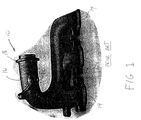
- FIG. 1 is a view of an exhaust manifold, representing a component suitable for being covered by the integral heat shield apparatus of the present invention.
- FIG. 2 is a view of one described embodiment of the heat shield of the present invention, installed over the exhaust manifold component of FIG. 1.
- FIG. 3 is a view of the embodiment of the heat shield of FIG. 2, rotated to reveal an aperture for accommodating protruding portions of the exhaust manifold component.
- FIG. 1 a conventional under-the-hood prior art engine component 10 is shown.
- the depicted component 10 is a heavy-duty cast-iron exhaust manifold adapted for being bolted to a plurality of exhaust ports of an internal combustion engine (not shown).
- the manifold 10 includes mounting bosses 12 for securement of a conventional metal heat shield, as will be appreciated by those skilled in the art. In the typical arrangement, a plurality of such bosses 12 are provided.
- the engine manifold 10 also contains a plurality of exhaust port flanges 14 for mounting the manifold 10 to the plurality of cylinder head exhaust ports of the aforesaid internal combustion engine.
- the exhaust port flanges 14 operate to collectively receive exhaust gases from individual combustion chambers of each engine, and to funnel the exhaust gases into a common port for transmission thereof out of the vehicle by way of an exhaust pipe portion 16 of the manifold 10 .
- a mounting flange 18 is integrally provided on the exhaust pipe portion 16 , as will also be appreciated by those skilled in the art.
- an integral, one-piece heat shield 20 is adapted to substantially encase the manifold 10 , as depicted.
- the heat shield 20 is defined by a pair of half-portions 19 and 21 that are integrally coupled together by a continuous bridge portion 22 .
- a split or gap 24 between half-portions 19 and 21 provides flexibility of installation onto the manifold 10 .
- at least one aperture 26 is provided in the heat shield 20 for accommodating protrusions of the exhaust pipe portion 16 and its associated mounting flange 18 .
- the aperture 26 is uninterrupted except for the intersection of the aperture with the gap 24 that extends lengthwise or longitudinally between half portions 19 and 20 and shown.
- the gap 24 defines a medial separation between the half-portions to permit the half-portions to be resiliently spread apart within limits as may be required.
- the heat shield 20 incorporates edges or extremities 28 that are folded over, and are thus trimmed to avoid injuries such as the cutting of hands and/or fingers of production line workers, or property damage such as cutting of the hoses and wires already attached in place to the engine.
- the heat shield 20 contains mounting grommets 30 that contain rotatable fasteners 32 , such as capscrews shown rotatably mounted within the grommets 30 .
- a plurality of such grommets and capscrews are employed in the embodiment described; normally at least two would be provided, one in each of the half-portions 19 and 21 .
- more of such grommets may be required to alleviate particularly difficult vibration issues, as those skilled in the art will appreciate.
- the heat shield 20 incorporates three layers; an outer layer of metal to provide structural integrity and overall rigidity, a center layer of insulation material to isolate temperature and to dampen of vibration and noise, and an inner metal layer adjacent the shielded component for reflecting heat back to the shielded component.
- the outer metal layer can be preferably formed of cold rolled steel, aluminized steel, aluminum, and even stainless steel in more exotic vehicles where cost is less of a factor. If cold rolled steel is utilized, the exterior of the shield should be coated with a corrosion-resistant material to enhance the longevity of the shield.
- the inner metal layer is the portion of the shield 20 that is in closest contact with the exhaust manifold. To the extent that the temperatures of the manifold can reach the 1600 degrees Fahrenheit range, the material of the inner metal layer should be able to withstand significant heat. In some applications the inner layer may be formed of high-temperature alloys, and in others can perhaps be of a cheaper aluminum-clad steel. Those skilled in the art will appreciate that choice of materials may be critical for avoiding degradation associated with elevated temperatures and considerable vibrations in particular applications.
- the material choices of the insulating and dampening center layer can be fairly broad. Such choices can include non-metallic fibers such as aramid fibers, or ceramic fiber paper. Depending on anticipated temperature ranges, even nonfiber compositions can be employed, such as densified vermiculite powders, as those skilled in the art will appreciate.
- One method of manufacturing of the heat shield 20 can be described as follows.
- the inner and outer metal layers are stamped from sheet metal, and then formed in a progressive die to the shapes depicted.
- the insulation layer is applied onto the outer metal layer, and then the inner metal layer is placed atop the insulation layer.
- the previously described edges 28 of the slightly oversized outer layer are folded over the respective mated edges of the inner metal layer, thus encapsulating the insulation layer between the metal layers.
- the grommets 30 along with the capscrews 32 can be applied via conventional methods, for example with the grommets 30 being trapped between the inner and outer metal layers, the capscrews 32 being rotatably secured within the grommets 30 , as can be purchased from a manufacturer.
- the unitary one-piece heat shield 20 can be handled by a single installer as opposed to a group of two or three installer as required to handle the conventional two-piece heat shield installation.
- the integrally contained mounting grommets 30 including the capscrews 32 rotatably mounted in the grommets, further facilitate fitment and securement of the heat shield 20 to the manifold component 10 .
Landscapes
- Engineering & Computer Science (AREA)
- Chemical & Material Sciences (AREA)
- Combustion & Propulsion (AREA)
- Mechanical Engineering (AREA)
- General Engineering & Computer Science (AREA)
- Exhaust Silencers (AREA)
Abstract
Description
- 1. Field of Invention
- The present invention relates to improved protective structures for vehicular engine parts that generate substantial heat and vibration during engine operation, such as exhaust manifolds. More particularly, the invention relates to protective heat shields applied to such parts for insulating the parts with respect to other components within an engine compartment of a vehicle.
- 2. Description of the Prior Art
- In today's modern vehicles, the exhaust manifolds of internal combustion engines can reach under-the-hood temperatures in the neighborhood of 1600 degrees Fahrenheit. Such high temperatures can create significant risks of damage to electronic components nested under the hood. Thus protection is warranted, and has been provided via use of heat shields designed to cover up, and hence to insulate, exhaust manifolds and other heat generating components. In some cases, the shields have been effective to reduce measured temperature levels to within a range of 300 degrees Fahrenheit, along with substantial commensurate reductions in noise levels. Typical heat shields, however, comprise several metal layers that have sharp edges prone to creating cuts in the hands and/or fingers of installers of such structures.
- In addition, many conventional heat shields are comprised of at least two entirely separate half-portions with at least three sets of detached capscrews and nuts required to hold the assembled half-portions together. In the typical production line, a minimum of two or three people are employed for such assembly of the heat shields, particularly when larger under the hood components, such as exhaust manifolds, are involved. Moreover, working with separate capscrew and nut components occasionally exacerbates nuisance factors in an assembly line environment, particularly in cases where several people are working together in close quarters.
- The present invention provides an improved insulated heat shield for engine components, such as exhaust manifolds of engines. In the described embodiment, a heat shield is formed of two contiguous halves to form a unitary structure adapted to be secured together via bolted connections to and about an engine manifold.
- In the described embodiment, the shield includes three layers; an outer layer of metal to provide overall structural integrity, a center layer of an insulation material to isolate heat and to dampen noise, and an inner layer adjacent the shielded component for reflecting heat back to the shielded component.
- In the described embodiment, the edges of the metal layers are folded over to avoid cutting hands and/or fingers of installers or assemblers, or even under-the-hood wiring and hose structures. In addition, the folded over edges provide reinforcement of the heat shield structure to minimize vibration, and to thus maximize service life. In addition, the capscrews and nuts are rotatably mounted firmly on integral grommets provided in the heat shield structure to permit a single installer to assemble the heat shield without requirement of assistance from fellow workers.
- FIG. 1 is a view of an exhaust manifold, representing a component suitable for being covered by the integral heat shield apparatus of the present invention.
- FIG. 2 is a view of one described embodiment of the heat shield of the present invention, installed over the exhaust manifold component of FIG. 1.
- FIG. 3 is a view of the embodiment of the heat shield of FIG. 2, rotated to reveal an aperture for accommodating protruding portions of the exhaust manifold component.
- Referring initially to FIG. 1, a conventional under-the-hood prior art engine component 10 is shown. The depicted component 10 is a heavy-duty cast-iron exhaust manifold adapted for being bolted to a plurality of exhaust ports of an internal combustion engine (not shown). The manifold 10 includes mounting bosses 12 for securement of a conventional metal heat shield, as will be appreciated by those skilled in the art. In the typical arrangement, a plurality of such bosses 12 are provided.
- The engine manifold 10 also contains a plurality of
exhaust port flanges 14 for mounting the manifold 10 to the plurality of cylinder head exhaust ports of the aforesaid internal combustion engine. Those skilled in the art will appreciate that theexhaust port flanges 14 operate to collectively receive exhaust gases from individual combustion chambers of each engine, and to funnel the exhaust gases into a common port for transmission thereof out of the vehicle by way of anexhaust pipe portion 16 of the manifold 10. Amounting flange 18 is integrally provided on theexhaust pipe portion 16, as will also be appreciated by those skilled in the art. - Referring now to FIGS. 2 and 3, an integral, one-piece heat shield 20 is adapted to substantially encase the manifold 10, as depicted. The heat shield 20 is defined by a pair of half-
portions continuous bridge portion 22. As will be apparent with particular reference to FIG. 3, a split orgap 24 between half-portions aperture 26 is provided in the heat shield 20 for accommodating protrusions of theexhaust pipe portion 16 and its associatedmounting flange 18. In the described embodiment, theaperture 26 is uninterrupted except for the intersection of the aperture with thegap 24 that extends lengthwise or longitudinally betweenhalf portions 19 and 20 and shown. Thegap 24 defines a medial separation between the half-portions to permit the half-portions to be resiliently spread apart within limits as may be required. - Continuing reference to FIG. 3, the heat shield 20 incorporates edges or
extremities 28 that are folded over, and are thus trimmed to avoid injuries such as the cutting of hands and/or fingers of production line workers, or property damage such as cutting of the hoses and wires already attached in place to the engine. - Those skilled in the art will recognize and appreciate the flexibility accorded by the design of the heat shield 20. To the extent that the heat shield body is formed of one piece, it is more easily installed over the manifold 10 than are conventional two-piece heat shields. To further facilitate ease of assembly, the heat shield 20 contains
mounting grommets 30 that contain rotatable fasteners 32, such as capscrews shown rotatably mounted within thegrommets 30. A plurality of such grommets and capscrews are employed in the embodiment described; normally at least two would be provided, one in each of the half-portions - In the described embodiment, the heat shield 20 incorporates three layers; an outer layer of metal to provide structural integrity and overall rigidity, a center layer of insulation material to isolate temperature and to dampen of vibration and noise, and an inner metal layer adjacent the shielded component for reflecting heat back to the shielded component. The outer metal layer can be preferably formed of cold rolled steel, aluminized steel, aluminum, and even stainless steel in more exotic vehicles where cost is less of a factor. If cold rolled steel is utilized, the exterior of the shield should be coated with a corrosion-resistant material to enhance the longevity of the shield.
- The inner metal layer is the portion of the shield 20 that is in closest contact with the exhaust manifold. To the extent that the temperatures of the manifold can reach the 1600 degrees Fahrenheit range, the material of the inner metal layer should be able to withstand significant heat. In some applications the inner layer may be formed of high-temperature alloys, and in others can perhaps be of a cheaper aluminum-clad steel. Those skilled in the art will appreciate that choice of materials may be critical for avoiding degradation associated with elevated temperatures and considerable vibrations in particular applications.
- The material choices of the insulating and dampening center layer can be fairly broad. Such choices can include non-metallic fibers such as aramid fibers, or ceramic fiber paper. Depending on anticipated temperature ranges, even nonfiber compositions can be employed, such as densified vermiculite powders, as those skilled in the art will appreciate.
- One method of manufacturing of the heat shield 20 can be described as follows. The inner and outer metal layers are stamped from sheet metal, and then formed in a progressive die to the shapes depicted. The insulation layer is applied onto the outer metal layer, and then the inner metal layer is placed atop the insulation layer. Next the previously described
edges 28 of the slightly oversized outer layer are folded over the respective mated edges of the inner metal layer, thus encapsulating the insulation layer between the metal layers. Thegrommets 30 along with the capscrews 32 can be applied via conventional methods, for example with thegrommets 30 being trapped between the inner and outer metal layers, the capscrews 32 being rotatably secured within thegrommets 30, as can be purchased from a manufacturer. - Those skilled in the art will appreciate that the unitary one-piece heat shield 20 can be handled by a single installer as opposed to a group of two or three installer as required to handle the conventional two-piece heat shield installation. The integrally contained
mounting grommets 30, including the capscrews 32 rotatably mounted in the grommets, further facilitate fitment and securement of the heat shield 20 to the manifold component 10. - It is to be understood that the above description is intended to be illustrative and not limiting. Many embodiments will be apparent to those of skill in the art upon reading the above description. Therefore, the scope of the invention should be determined, not with reference to the above description, but instead with reference to the appended claims, along with the full scope of equivalents to which such claims are entitled.
Claims (12)
Priority Applications (4)
| Application Number | Priority Date | Filing Date | Title |
|---|---|---|---|
| US09/879,879 US6598389B2 (en) | 2001-06-12 | 2001-06-12 | Insulated heat shield |
| JP2002169718A JP2002371842A (en) | 2001-06-12 | 2002-06-11 | Insulated heat shield |
| CA2390467A CA2390467C (en) | 2001-06-12 | 2002-06-11 | Insulated heat shield |
| MXPA02005839A MXPA02005839A (en) | 2001-06-12 | 2002-06-12 | Insulated heat shield. |
Applications Claiming Priority (1)
| Application Number | Priority Date | Filing Date | Title |
|---|---|---|---|
| US09/879,879 US6598389B2 (en) | 2001-06-12 | 2001-06-12 | Insulated heat shield |
Publications (2)
| Publication Number | Publication Date |
|---|---|
| US20020184880A1 true US20020184880A1 (en) | 2002-12-12 |
| US6598389B2 US6598389B2 (en) | 2003-07-29 |
Family
ID=25375071
Family Applications (1)
| Application Number | Title | Priority Date | Filing Date |
|---|---|---|---|
| US09/879,879 Expired - Lifetime US6598389B2 (en) | 2001-06-12 | 2001-06-12 | Insulated heat shield |
Country Status (4)
| Country | Link |
|---|---|
| US (1) | US6598389B2 (en) |
| JP (1) | JP2002371842A (en) |
| CA (1) | CA2390467C (en) |
| MX (1) | MXPA02005839A (en) |
Cited By (2)
| Publication number | Priority date | Publication date | Assignee | Title |
|---|---|---|---|---|
| US20040202807A1 (en) * | 2003-04-09 | 2004-10-14 | Earnest Robert D. | Insulated material and articles made therefrom |
| US20050193726A1 (en) * | 2004-03-03 | 2005-09-08 | Nissan Motor Co., Ltd. | Heat shield structure of exhaust manifold and catalyst |
Families Citing this family (20)
| Publication number | Priority date | Publication date | Assignee | Title |
|---|---|---|---|---|
| US20040177609A1 (en) * | 2001-12-07 | 2004-09-16 | Moore Dan T. | Insulated exhaust manifold having ceramic inner layer that is highly resistant to thermal cycling |
| JP3940053B2 (en) * | 2002-09-30 | 2007-07-04 | 本田技研工業株式会社 | Heat shield device for exhaust system of internal combustion engine |
| US7146807B1 (en) * | 2003-10-15 | 2006-12-12 | Mondelci Thomas H | Exhaust manifold heat shield |
| DE102005006319A1 (en) * | 2005-02-11 | 2006-08-24 | Elringklinger Ag | Shielding part, in particular heat shield |
| DE102005006320A1 (en) * | 2005-02-11 | 2006-08-24 | Elringklinger Ag | Shielding part, in particular heat shield |
| DE102006003229A1 (en) * | 2006-01-24 | 2007-08-02 | Federal-Mogul Sealing Systems Gmbh | Heat shield, for exhaust gas manifold, for example, consists of several elements which at least partially overlap one another, wherein in overlapping region the elements are fixed at least in places but can move relative to one another |
| JP2008240589A (en) * | 2007-03-27 | 2008-10-09 | Kokusan Buhin Kogyo Kk | Engine exhaust structure |
| US20080236693A1 (en) * | 2007-03-30 | 2008-10-02 | Norman Everett Muzzy | Exhaust pipe assembly |
| DE202007009806U1 (en) * | 2007-06-01 | 2008-07-03 | Bdd Beteiligungs Gmbh | Insulating device for a machine element, in particular exhaust pipe |
| DE202008008690U1 (en) | 2008-06-27 | 2008-09-18 | Reinz-Dichtungs-Gmbh | heat shield |
| US9851162B2 (en) * | 2014-08-05 | 2017-12-26 | Air International, Inc. | Cover for heat source |
| DE102015100994A1 (en) * | 2015-01-23 | 2016-07-28 | Faurecia Emissions Control Technologies, Germany Gmbh | Heat shield assembly for a vehicle exhaust system and exhaust system component of a motor vehicle |
| US10443440B2 (en) * | 2015-04-09 | 2019-10-15 | United Technologies Corporation | Heat shield, systems and methods |
| US10604087B2 (en) | 2015-06-02 | 2020-03-31 | Lydall, Inc. | Heat shield with sealing member |
| US9982579B2 (en) * | 2015-07-07 | 2018-05-29 | United Technologies Corporation | Thermally compliant heatshield |
| DE102015113042B4 (en) | 2015-08-07 | 2023-10-12 | Dbw Advanced Fiber Technologies Gmbh | Acoustic absorption component, arrangement formed therewith and method for producing an absorption component |
| US10502137B2 (en) | 2015-10-19 | 2019-12-10 | General Electric Company | Gas turbine with a valve cooling system |
| US10544724B2 (en) * | 2016-03-24 | 2020-01-28 | Faurecia Emissions Control Technologies, Usa, Llc | Vehicle exhaust system component having an insulating heat shield assembly with encapsulated pockets |
| US10371005B2 (en) * | 2016-07-20 | 2019-08-06 | United Technologies Corporation | Multi-ply heat shield assembly with integral band clamp for a gas turbine engine |
| EP3995672B1 (en) | 2020-11-10 | 2025-12-24 | GE Vernova Technology GmbH | Systems and methods for controlling temperature in a supporting foundation used with a gas turbine engine |
Family Cites Families (13)
| Publication number | Priority date | Publication date | Assignee | Title |
|---|---|---|---|---|
| JPS5138383B2 (en) | 1972-08-22 | 1976-10-21 | ||
| US4612767A (en) | 1985-03-01 | 1986-09-23 | Caterpillar Inc. | Exhaust manifold shield |
| JPH0716018Y2 (en) | 1988-05-19 | 1995-04-12 | スズキ株式会社 | Exhaust manifold heat shield |
| JPH072975Y2 (en) | 1988-05-24 | 1995-01-30 | スズキ株式会社 | Exhaust manifold cover assembly structure |
| US5233832A (en) | 1992-05-14 | 1993-08-10 | Soundwich, Inc. | Damped heat shield |
| US5590524A (en) | 1992-05-14 | 1997-01-07 | Soundwich, Inc. | Damped heat shield |
| US5278002A (en) * | 1992-09-22 | 1994-01-11 | Lydall, Inc. | Battery cover |
| US5419127A (en) * | 1993-11-22 | 1995-05-30 | Soundwich Inc | Insulated damped exhaust manifold |
| US6026846A (en) * | 1996-01-02 | 2000-02-22 | Acoust-A-Fiber Research & Development, Inc. | Shield encompassing a hot pipe |
| US5816043A (en) | 1996-01-02 | 1998-10-06 | Acoust-A-Fiber Research And Development, Inc. | Shield encompassing a hot pipe |
| DE19849366A1 (en) * | 1998-10-20 | 2000-04-27 | J & S Gmbh Werkzeugbau Stanz U | Sandwich shield plate consists of non-metallic intermediate layer between two metal sheets, and structural elements in one sheet |
| US6141958A (en) * | 1998-12-31 | 2000-11-07 | Voss; Randy E. | Exhaust cooling system for vehicles |
| US6318734B1 (en) * | 1999-12-21 | 2001-11-20 | Dana Corporation | Gasket with integral support |
-
2001
- 2001-06-12 US US09/879,879 patent/US6598389B2/en not_active Expired - Lifetime
-
2002
- 2002-06-11 CA CA2390467A patent/CA2390467C/en not_active Expired - Fee Related
- 2002-06-11 JP JP2002169718A patent/JP2002371842A/en active Pending
- 2002-06-12 MX MXPA02005839A patent/MXPA02005839A/en active IP Right Grant
Cited By (4)
| Publication number | Priority date | Publication date | Assignee | Title |
|---|---|---|---|---|
| US20040202807A1 (en) * | 2003-04-09 | 2004-10-14 | Earnest Robert D. | Insulated material and articles made therefrom |
| US20050193726A1 (en) * | 2004-03-03 | 2005-09-08 | Nissan Motor Co., Ltd. | Heat shield structure of exhaust manifold and catalyst |
| EP1577516A1 (en) * | 2004-03-03 | 2005-09-21 | Nissan Motor Co., Ltd. | Heat shield structure of exhaust manifold and catalyst |
| US7162868B2 (en) | 2004-03-03 | 2007-01-16 | Nissan Motor Co., Ltd. | Heat shield structure of exhaust manifold and catalyst |
Also Published As
| Publication number | Publication date |
|---|---|
| CA2390467C (en) | 2011-10-04 |
| CA2390467A1 (en) | 2002-12-12 |
| US6598389B2 (en) | 2003-07-29 |
| MXPA02005839A (en) | 2004-12-13 |
| JP2002371842A (en) | 2002-12-26 |
Similar Documents
| Publication | Publication Date | Title |
|---|---|---|
| US6598389B2 (en) | Insulated heat shield | |
| US6581720B1 (en) | Noise attenuating insulated heat shield | |
| US6797402B2 (en) | Insulated heat shield with waved edge | |
| EP1563516B1 (en) | Cable duct for a vehicle | |
| US6670020B1 (en) | Honeycomb body configuration with an intermediate layer containing at least one metal layer and sandwich structure in particular for a honeycomb body configuration | |
| ZA200404212B (en) | Fuel saving combustion engine insulation method and systems. | |
| US20090013679A1 (en) | Engine exhaust structure | |
| US6009706A (en) | Exhaust manifold assembly in an internal combustion engine | |
| US5452577A (en) | Exhaust gas system for an internal combustion engine | |
| CA2413318A1 (en) | Sound barrier layer for insulated heat shield | |
| US20060194025A1 (en) | Multi-layer dimpled heat shields | |
| CN1289390A (en) | Catalytic exhaust gas cleaning system and corresponding compensation layer, especially for motor vehicles | |
| US6811159B2 (en) | Gasket and heat shield for a flanged joint | |
| US20120148853A1 (en) | Insulator | |
| US20070098954A1 (en) | Plastic/metal hybrid engine shield | |
| SE455330B (en) | EXHAUST GAS POLLUTION FOR MULTI-CYLINDRY ENGINE COMBUSTION ENGINES | |
| KR20120051100A (en) | Structural component, in particular a shield | |
| JPH0797922A (en) | Exhaust pipe for automobile and manufacture thereof | |
| US5958347A (en) | Pre-converter mounting device | |
| GB2336194A (en) | Insulating device | |
| JPH0248678Y2 (en) | ||
| CN223676366U (en) | A three-layer heat insulation cover structure | |
| JP2023141017A (en) | Exhaust pipe heat shield structure | |
| JPH0329536Y2 (en) | ||
| JP2002046481A (en) | Engine support structure |
Legal Events
| Date | Code | Title | Description |
|---|---|---|---|
| AS | Assignment |
Owner name: DANA CORPORATION, OHIO Free format text: ASSIGNMENT OF ASSIGNORS INTEREST;ASSIGNORS:CHEN, COLIN CHING-HO;POPIELAS, FRANK W.;BOOGEMANS, MARK;AND OTHERS;REEL/FRAME:012704/0984;SIGNING DATES FROM 20011019 TO 20011129 |
|
| STCF | Information on status: patent grant |
Free format text: PATENTED CASE |
|
| AS | Assignment |
Owner name: DANA CORPORATION, OHIO Free format text: CORRECTIVE ASSIGNMENT TO ADD INVENTORS TO PREVIOUSLY RECORDED ASSIGNMENT RECORDED ON 03/12/2002 REEL 012704, FRAME 0984;ASSIGNORS:CHEN, COLIN C.;BOOGEMANS, MARK;MATIAS, CALIN;AND OTHERS;REEL/FRAME:014567/0318;SIGNING DATES FROM 20011019 TO 20030319 |
|
| CC | Certificate of correction | ||
| FEPP | Fee payment procedure |
Free format text: PAYOR NUMBER ASSIGNED (ORIGINAL EVENT CODE: ASPN); ENTITY STATUS OF PATENT OWNER: LARGE ENTITY |
|
| FPAY | Fee payment |
Year of fee payment: 4 |
|
| AS | Assignment |
Owner name: DANA AUTOMOTIVE SYSTEMS GROUP, LLC, OHIO Free format text: ASSIGNMENT OF ASSIGNORS INTEREST;ASSIGNOR:DANA CORPORATION;REEL/FRAME:020540/0476 Effective date: 20080131 Owner name: DANA AUTOMOTIVE SYSTEMS GROUP, LLC,OHIO Free format text: ASSIGNMENT OF ASSIGNORS INTEREST;ASSIGNOR:DANA CORPORATION;REEL/FRAME:020540/0476 Effective date: 20080131 |
|
| AS | Assignment |
Owner name: CITICORP USA, INC., NEW YORK Free format text: INTELLECTUAL PROPERTY TERM FACILITY SECURITY AGREEMENT;ASSIGNORS:DANA HOLDING CORPORATION;DANA LIMITED;DANA AUTOMOTIVE SYSTEMS GROUP, LLC;AND OTHERS;REEL/FRAME:020859/0359 Effective date: 20080131 Owner name: CITICORP USA, INC., NEW YORK Free format text: INTELLECTUAL PROPERTY REVOLVING FACILITY SECURITY AGREEMENT;ASSIGNORS:DANA HOLDING CORPORATION;DANA LIMITED;DANA AUTOMOTIVE SYSTEMS GROUP, LLC;AND OTHERS;REEL/FRAME:020859/0249 Effective date: 20080131 Owner name: CITICORP USA, INC.,NEW YORK Free format text: INTELLECTUAL PROPERTY REVOLVING FACILITY SECURITY AGREEMENT;ASSIGNORS:DANA HOLDING CORPORATION;DANA LIMITED;DANA AUTOMOTIVE SYSTEMS GROUP, LLC;AND OTHERS;REEL/FRAME:020859/0249 Effective date: 20080131 Owner name: CITICORP USA, INC.,NEW YORK Free format text: INTELLECTUAL PROPERTY TERM FACILITY SECURITY AGREEMENT;ASSIGNORS:DANA HOLDING CORPORATION;DANA LIMITED;DANA AUTOMOTIVE SYSTEMS GROUP, LLC;AND OTHERS;REEL/FRAME:020859/0359 Effective date: 20080131 |
|
| FEPP | Fee payment procedure |
Free format text: PAYOR NUMBER ASSIGNED (ORIGINAL EVENT CODE: ASPN); ENTITY STATUS OF PATENT OWNER: LARGE ENTITY Free format text: PAYER NUMBER DE-ASSIGNED (ORIGINAL EVENT CODE: RMPN); ENTITY STATUS OF PATENT OWNER: LARGE ENTITY |
|
| FPAY | Fee payment |
Year of fee payment: 8 |
|
| FPAY | Fee payment |
Year of fee payment: 12 |
|
| AS | Assignment |
Owner name: CITIBANK, N.A., NEW YORK Free format text: SECURITY AGREEMENT SUPPLEMENT;ASSIGNORS:DANA HEAVY VEHICLE SYSTEMS GROUP, LLC;DANA LIMITED;DANA AUTOMOTIVE SYSTEMS GROUP, LLC;AND OTHERS;REEL/FRAME:052459/0224 Effective date: 20200416 Owner name: CITIBANK, N.A., NEW YORK Free format text: SECURITY AGREEMENT (BRIDGE);ASSIGNORS:DANA HEAVY VEHICLE SYSTEMS GROUP, LLC;DANA LIMITED;DANA AUTOMOTIVE SYSTEMS GROUP, LLC;AND OTHERS;REEL/FRAME:052459/0001 Effective date: 20200416 |
|
| AS | Assignment |
Owner name: DANA LIMITED, OHIO Free format text: RELEASE BY SECURED PARTY;ASSIGNOR:CITIBANK, N.A.;REEL/FRAME:053309/0686 Effective date: 20200619 Owner name: DANA AUTOMOTIVE SYSTEMS GROUP, LLC, OHIO Free format text: RELEASE BY SECURED PARTY;ASSIGNOR:CITIBANK, N.A.;REEL/FRAME:053309/0686 Effective date: 20200619 Owner name: DANA HEAVY VEHICLE SYSTEMS GROUP, LLC, OHIO Free format text: RELEASE BY SECURED PARTY;ASSIGNOR:CITIBANK, N.A.;REEL/FRAME:053309/0686 Effective date: 20200619 Owner name: FAIRFIELD MANUFACTURING COMPANY, INC., OHIO Free format text: RELEASE BY SECURED PARTY;ASSIGNOR:CITIBANK, N.A.;REEL/FRAME:053309/0686 Effective date: 20200619 |