US20020184876A1 - Fueling control system - Google Patents
Fueling control system Download PDFInfo
- Publication number
- US20020184876A1 US20020184876A1 US09/772,549 US77254901A US2002184876A1 US 20020184876 A1 US20020184876 A1 US 20020184876A1 US 77254901 A US77254901 A US 77254901A US 2002184876 A1 US2002184876 A1 US 2002184876A1
- Authority
- US
- United States
- Prior art keywords
- exhaust gas
- gas sensor
- stoichiometry
- control device
- emission control
- Prior art date
- Legal status (The legal status is an assumption and is not a legal conclusion. Google has not performed a legal analysis and makes no representation as to the accuracy of the status listed.)
- Granted
Links
- 239000000446 fuel Substances 0.000 claims abstract description 69
- 238000011144 upstream manufacturing Methods 0.000 claims abstract description 21
- 238000002347 injection Methods 0.000 claims description 13
- 239000007924 injection Substances 0.000 claims description 13
- 238000001914 filtration Methods 0.000 claims description 7
- 239000007800 oxidant agent Substances 0.000 claims description 5
- 238000004590 computer program Methods 0.000 claims 1
- 238000000034 method Methods 0.000 abstract description 6
- 239000007789 gas Substances 0.000 description 15
- 230000006870 function Effects 0.000 description 10
- 239000003054 catalyst Substances 0.000 description 8
- 238000005070 sampling Methods 0.000 description 8
- 238000012937 correction Methods 0.000 description 7
- 238000002485 combustion reaction Methods 0.000 description 6
- 238000013459 approach Methods 0.000 description 4
- QVGXLLKOCUKJST-UHFFFAOYSA-N atomic oxygen Chemical compound [O] QVGXLLKOCUKJST-UHFFFAOYSA-N 0.000 description 4
- 230000008901 benefit Effects 0.000 description 4
- 238000005259 measurement Methods 0.000 description 4
- 239000001301 oxygen Substances 0.000 description 4
- 229910052760 oxygen Inorganic materials 0.000 description 4
- 239000000498 cooling water Substances 0.000 description 3
- 238000012546 transfer Methods 0.000 description 3
- 101100219315 Arabidopsis thaliana CYP83A1 gene Proteins 0.000 description 2
- 101100269674 Mus musculus Alyref2 gene Proteins 0.000 description 2
- 101100502522 Mus musculus Fcor gene Proteins 0.000 description 2
- 101100140580 Saccharomyces cerevisiae (strain ATCC 204508 / S288c) REF2 gene Proteins 0.000 description 2
- 230000008859 change Effects 0.000 description 2
- 238000010586 diagram Methods 0.000 description 2
- 230000009977 dual effect Effects 0.000 description 2
- 230000000717 retained effect Effects 0.000 description 2
- 101000806846 Homo sapiens DNA-(apurinic or apyrimidinic site) endonuclease Proteins 0.000 description 1
- 101000835083 Homo sapiens Tissue factor pathway inhibitor 2 Proteins 0.000 description 1
- 102100026134 Tissue factor pathway inhibitor 2 Human genes 0.000 description 1
- 230000009471 action Effects 0.000 description 1
- 230000004913 activation Effects 0.000 description 1
- 239000003638 chemical reducing agent Substances 0.000 description 1
- 239000002826 coolant Substances 0.000 description 1
- 238000012545 processing Methods 0.000 description 1
- 230000002035 prolonged effect Effects 0.000 description 1
- 230000004044 response Effects 0.000 description 1
- 238000010792 warming Methods 0.000 description 1
Images


Classifications
-
- F—MECHANICAL ENGINEERING; LIGHTING; HEATING; WEAPONS; BLASTING
- F02—COMBUSTION ENGINES; HOT-GAS OR COMBUSTION-PRODUCT ENGINE PLANTS
- F02D—CONTROLLING COMBUSTION ENGINES
- F02D41/00—Electrical control of supply of combustible mixture or its constituents
- F02D41/02—Circuit arrangements for generating control signals
- F02D41/14—Introducing closed-loop corrections
- F02D41/1438—Introducing closed-loop corrections using means for determining characteristics of the combustion gases; Sensors therefor
- F02D41/1473—Introducing closed-loop corrections using means for determining characteristics of the combustion gases; Sensors therefor characterised by the regulation method
- F02D41/1475—Regulating the air fuel ratio at a value other than stoichiometry
-
- F—MECHANICAL ENGINEERING; LIGHTING; HEATING; WEAPONS; BLASTING
- F02—COMBUSTION ENGINES; HOT-GAS OR COMBUSTION-PRODUCT ENGINE PLANTS
- F02D—CONTROLLING COMBUSTION ENGINES
- F02D41/00—Electrical control of supply of combustible mixture or its constituents
- F02D41/02—Circuit arrangements for generating control signals
- F02D41/14—Introducing closed-loop corrections
- F02D41/1438—Introducing closed-loop corrections using means for determining characteristics of the combustion gases; Sensors therefor
- F02D41/1439—Introducing closed-loop corrections using means for determining characteristics of the combustion gases; Sensors therefor characterised by the position of the sensor
- F02D41/1441—Plural sensors
-
- F—MECHANICAL ENGINEERING; LIGHTING; HEATING; WEAPONS; BLASTING
- F02—COMBUSTION ENGINES; HOT-GAS OR COMBUSTION-PRODUCT ENGINE PLANTS
- F02D—CONTROLLING COMBUSTION ENGINES
- F02D2200/00—Input parameters for engine control
- F02D2200/02—Input parameters for engine control the parameters being related to the engine
- F02D2200/04—Engine intake system parameters
- F02D2200/0404—Throttle position
-
- F—MECHANICAL ENGINEERING; LIGHTING; HEATING; WEAPONS; BLASTING
- F02—COMBUSTION ENGINES; HOT-GAS OR COMBUSTION-PRODUCT ENGINE PLANTS
- F02D—CONTROLLING COMBUSTION ENGINES
- F02D2200/00—Input parameters for engine control
- F02D2200/02—Input parameters for engine control the parameters being related to the engine
- F02D2200/04—Engine intake system parameters
- F02D2200/0406—Intake manifold pressure
-
- F—MECHANICAL ENGINEERING; LIGHTING; HEATING; WEAPONS; BLASTING
- F02—COMBUSTION ENGINES; HOT-GAS OR COMBUSTION-PRODUCT ENGINE PLANTS
- F02D—CONTROLLING COMBUSTION ENGINES
- F02D2200/00—Input parameters for engine control
- F02D2200/02—Input parameters for engine control the parameters being related to the engine
- F02D2200/04—Engine intake system parameters
- F02D2200/0414—Air temperature
-
- F—MECHANICAL ENGINEERING; LIGHTING; HEATING; WEAPONS; BLASTING
- F02—COMBUSTION ENGINES; HOT-GAS OR COMBUSTION-PRODUCT ENGINE PLANTS
- F02D—CONTROLLING COMBUSTION ENGINES
- F02D41/00—Electrical control of supply of combustible mixture or its constituents
- F02D41/02—Circuit arrangements for generating control signals
- F02D41/14—Introducing closed-loop corrections
- F02D41/1438—Introducing closed-loop corrections using means for determining characteristics of the combustion gases; Sensors therefor
- F02D41/1444—Introducing closed-loop corrections using means for determining characteristics of the combustion gases; Sensors therefor characterised by the characteristics of the combustion gases
- F02D41/1454—Introducing closed-loop corrections using means for determining characteristics of the combustion gases; Sensors therefor characterised by the characteristics of the combustion gases the characteristics being an oxygen content or concentration or the air-fuel ratio
- F02D41/1456—Introducing closed-loop corrections using means for determining characteristics of the combustion gases; Sensors therefor characterised by the characteristics of the combustion gases the characteristics being an oxygen content or concentration or the air-fuel ratio with sensor output signal being linear or quasi-linear with the concentration of oxygen
-
- F—MECHANICAL ENGINEERING; LIGHTING; HEATING; WEAPONS; BLASTING
- F02—COMBUSTION ENGINES; HOT-GAS OR COMBUSTION-PRODUCT ENGINE PLANTS
- F02D—CONTROLLING COMBUSTION ENGINES
- F02D41/00—Electrical control of supply of combustible mixture or its constituents
- F02D41/02—Circuit arrangements for generating control signals
- F02D41/18—Circuit arrangements for generating control signals by measuring intake air flow
- F02D41/187—Circuit arrangements for generating control signals by measuring intake air flow using a hot wire flow sensor
-
- F—MECHANICAL ENGINEERING; LIGHTING; HEATING; WEAPONS; BLASTING
- F02—COMBUSTION ENGINES; HOT-GAS OR COMBUSTION-PRODUCT ENGINE PLANTS
- F02D—CONTROLLING COMBUSTION ENGINES
- F02D41/00—Electrical control of supply of combustible mixture or its constituents
- F02D41/30—Controlling fuel injection
- F02D41/32—Controlling fuel injection of the low pressure type
-
- F—MECHANICAL ENGINEERING; LIGHTING; HEATING; WEAPONS; BLASTING
- F02—COMBUSTION ENGINES; HOT-GAS OR COMBUSTION-PRODUCT ENGINE PLANTS
- F02D—CONTROLLING COMBUSTION ENGINES
- F02D41/00—Electrical control of supply of combustible mixture or its constituents
- F02D41/30—Controlling fuel injection
- F02D41/38—Controlling fuel injection of the high pressure type
- F02D41/3809—Common rail control systems
-
- F—MECHANICAL ENGINEERING; LIGHTING; HEATING; WEAPONS; BLASTING
- F02—COMBUSTION ENGINES; HOT-GAS OR COMBUSTION-PRODUCT ENGINE PLANTS
- F02P—IGNITION, OTHER THAN COMPRESSION IGNITION, FOR INTERNAL-COMBUSTION ENGINES; TESTING OF IGNITION TIMING IN COMPRESSION-IGNITION ENGINES
- F02P5/00—Advancing or retarding ignition; Control therefor
- F02P5/04—Advancing or retarding ignition; Control therefor automatically, as a function of the working conditions of the engine or vehicle or of the atmospheric conditions
- F02P5/145—Advancing or retarding ignition; Control therefor automatically, as a function of the working conditions of the engine or vehicle or of the atmospheric conditions using electrical means
- F02P5/15—Digital data processing
- F02P5/1502—Digital data processing using one central computing unit
- F02P5/1504—Digital data processing using one central computing unit with particular means during a transient phase, e.g. acceleration, deceleration, gear change
Definitions
- the present invention relates to a combined lean burn and stoichiometric fuel control for an automotive internal combustion engine.
- Engine air-fuel ratio control typically uses an exhaust gas oxygen sensor for feedback control.
- One system shows a “linear” exhaust gas sensor upstream of catalyst and a “switching” exhaust gas sensor downstream of the catalyst.
- the “switching” sensor is used to monitor the catalyst and the “linear” sensor.
- the “switching” sensor is used for air-fuel control during engine start until the “linear” sensor reaches its operating temperature. However, whenever the “linear” sensor attains the activation temperature, it is utilized to control engine air-fuel ratio.
- Such a method is described U.S. Pat. No. 5,832,724.
- the inventors herein have recognized a disadvantage of the above approach.
- the “linear” sensor has less accuracy in determining the point of stoichiometry than the “switching” sensor. This is generally because the “linear” sensor is designed to provide a signal indicative of actual air-fuel ratio over a wide air-fuel ratio range, whereas the “switching” sensor is designed to produce a very large change (“switch”) at the point of stoichiometry.
- switch very large change
- a system for controlling engine air-fuel ratio entering an emission control device comprising: a switching exhaust gas sensor located downstream of the emission control device; a linear exhaust gas sensor located upstream of the emission control device; and a controller adjusting a fuel injection amount into the engine based on both said switching exhaust gas sensor and said linear exhaust gas sensor when operating near stoichiometry; and adjusting said fuel injection amount into the engine based on said linear exhaust gas sensor and independent of said switching exhaust gas sensor when operating away from stoichiometry.
- An advantage of the above aspect of the present invention is improved emissions and improved fuel economy.
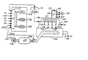
- FIG. 1 is a schematic view of an internal combustion engine including an embodiment of this invention
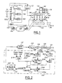
- FIG. 2 is a control block diagram of an upstream UEGO and downstream EGO sensor closed loop fuel control system according to the invention
- FIG. 3 is a graph showing typical voltage output of an EGO sensor as a function of air/fuel ratio
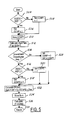
- FIG. 4 is a flowchart illustrating various process steps performed to calculate fuel flow rate in accordance with an embodiment of this invention
- FIG. 5 is a flowchart illustrating various process steps performed to calculate an air/fuel ratio correction amount according to the invention
- FIG. 6 is a graph showing typical voltage output of an UEGO sensor as a function of air/fuel ratio
- FIG. 7 is a flowchart illustrating various process steps performed to calculate an air/fuel ratio correction amount according to the invention.
- microcomputer 100 for controlling an air/fuel ratio supplied to an internal combustion engine 102 .
- Microcomputer 100 further comprises a central processing unit (CPU) 104 , a read-only memory (ROM) 106 for storing main routine and other routines such as a fuel flow routine and calibration constants, tables, etc., a random access memory (RAM) 108 , and a conventional input/output (I/O) interface 110 .
- Interface 110 includes analog to digital (A/D) converters for converting various analog input signals and digital inputs, digital to analog (D/A) converters for converting various analog output signals and digital outputs.
- Microcomputer 100 also includes conventional elements such as a clock generator and means for generating various clock signals, counters, drivers, and the like (not shown). Microcomputer 100 controls the air/fuel ratio by energizing injector drivers 112 in response to various measured operating parameters of engine 102 . Microcomputer 100 can fetch input parameters and can perform calculations of control signals at a fixed sampling rate DELTAT such as, for example, 20 msec. If microcomputer 100 is designed to operate with a variable sampling rate, a timer can be provided which can perform time measurement between two successive samplings and assign measured sampling time to DELTAT.
- DELTAT fixed sampling rate
- a timer can be provided which can perform time measurement between two successive samplings and assign measured sampling time to DELTAT.
- Engine 102 in this particular example, is shown as a conventional four cylinder gasoline engine having fuel injectors 114 , 116 , 118 , and 120 coupled to a fuel rail 121 .
- Each fuel injector is electronically activated by respective signals from injector drivers 112 .
- Each of the injectors 114 , 116 , 118 , and 120 is also coupled in a conventional manner to respective combustion cylinders 1 , 2 , 3 , and 4 (not shown).
- Exhaust gases from each of the combustion cylinders 1 , 2 , 3 , and 4 are routed to an exhaust manifold 122 and are discharged through an emission control device 124 which removes CO, HC, and NOx from the exhaust gas, and exhaust pipe 126 .
- Emission control device 124 operates to retain oxidants (NOx and O2) during lean operating, and releases the retained oxidants during rich operation, where the incoming reductants react with the released oxidants.
- a UEGO (UEGO) sensor 128 for detecting an oxygen concentration in the engine exhaust gases, which provides an output proportional to exhaust air-fuel ratio concentration over a wide range of air-fuel ratios.
- an EGO sensor 130 [“switching” exhaust gas sensor] for detecting an oxygen concentration after catalyst 124 .
- EGO sensor provides an abrupt change in output voltage at the point of stoichiometry. Both the UEGO and EGO sensors 128 and 130 generate output voltage signals that are transmitted to the A/D converter of I/O interface 110 .
- Intake air port 132 is shown coupled to intake manifold 134 for inducting air past throttle plate 136 into combustion cylinders.
- Throttle position sensor 138 is shown coupled to throttle plate 136 for providing a throttle position signal TP.
- mass airflow sensor 140 is also coupled to intake manifold 134 for providing mass airflow signal MAF related to the mass airflow induced into engine, and air temperature sensor 142 for providing a signal TA indicative of the temperature of induced air.
- Coupled to a cylinder block of engine 102 is a cooling water temperature sensor 144 for providing signal TW indicative of the coolant temperature.
- Crank angle position sensor 146 is shown coupled to a crankshaft of engine 102 for providing crank angle position signal CA indicative of crank position.
- a manifold pressure sensor MAP may be used instead of a mass airflow sensor 140 to provide an indication of engine load by known techniques.
- Other conventional components necessary for engine operations such as a spark delivery system are not shown in FIG. 1. It is also recognized that the invention may be used to advantage with other types of engines, such as engines having a number of cylinders other than four. Further a direct injection engine may be used with the present invention.
- FIG. 2 The operation of a UEGO and EGO sensor closed loop fuel control system in controlling air/fuel ratio is now described with particular reference to a control block diagram shown in FIG. 2, the associated graph in FIG. 3 showing EGO sensor output voltage VEGO versus LAMBDA, an air/fuel ratio relative to air/fuel stoichiometric ratio, and the associated graph in FIG. 6 showing UEGO sensor output voltage VUEGO versus LAMBDA.
- microcomputer 100 , engine 102 , injector drivers 112 , exhaust manifold 122 , catalyst 124 , exhaust pipe 125 , and UEGO and EGO sensors 128 and 130 have been previously described with reference to FIG. 1.
- Output voltages VUEGO and VEGO from upstream UEGO sensor 128 and downstream EGO sensor 130 are fed through A/D converter (not shown) to respective comparators 200 and 202 .
- Each comparator is supplied with reference signals REF 1 and REF 2 , respectively, which are indicative of an EGO output voltage at stoichiometric ratio as shown in FIG. 3.
- Each comparator 200 and 202 produces an output signal COMP 1 and COMP 2 respectively in such a way that their absolute values are equal but vary in sign depending upon which side of stoichiometric ratio are EGO output voltage signals VUEGO and VEGO respectively.
- the output COMP 1 of comparator 200 is modified by corrective block 204 .
- Corrective block 204 is advantageously a high pass filter, which in this embodiment is presented as a first order high pass filter but is not limited to be a first order filter and may be a higher order high pass filter.
- high pass filter includes filters who simply have a high pass filter component. In other words, a filter may have both high pass and low pass characteristics.
- any filter with zeros in the numerator of the transfer function may constitute a high pass filtering component of a filter.
- a high pass filter may be present when the order of the numerator of the filter transfer function is greater than the order of the denominator.
- high pass filter is disabled during operation away from stoichiometry as described later herein with particular reference to FIG. 7.
- the first order high pass filter also known in the control field as a real time differentiator, may be described by the following differential equation:
- DIF the first order high pass filter output signal
- T d time constant of said filter, calibratable parameter of the control system
- d( . . . )/dt symbol indicating the first derivative of the respective signal.
- DELTAT microcomputer sampling rate discussed above
- i and i ⁇ 1 indicate current and previous results of calculations or measurements.
- the output COMP 2 of the second comparator 202 is connected to gain block 206 with a constant gain K so that output signal of comparator 202 is equal to K*COMP 2 .
- Output signals of both comparators 200 and 202 are summed together with an additional bias signal BIAS by a summing block 208 .
- Said bias signal BIAS is provided for calibration purposes only serving to modify reference signal REF 2 if so desired.
- the output signal SUM of the summing block is equal
- Controller block 210 performs calculation corresponding to proportional and integral (PI) controller which is described by the following differential equation:
- LAMCOR output signal of PI controller which represents air/fuel ratio correction amount
- H and G jumpback and ramp respectively of the PI controller, calibratable parameters of the control system.
- Fuel calculation block 212 calculates fuel flow control signal in a conventional manner using an air/fuel correction amount LAMCOR, and provides signals to injector drivers 112 .
- Function generator 300 is coupled to the first comparitor 200 and generates the first reference voltage. In other words, function generator 300 generates the desired air-fuel ratio reference for engine operating. When lean operation away from stoichiometry is desired, the function generator generates a value greater than 1. When rich operation away from stoichiometry is desired, the function generator generates a value less than 1. When near stoichiometric operation away from stoichiometry is desired, the function generator generates a value near or substantially 1.
- microcomputer 100 in controlling fuel flow is now described with particular reference to the flowchart shown in FIG. 4.
- the operations, or steps, described herein below are performed for each cylinder.
- cylinder identification and injector driver selection is not explicitly mentioned.
- step 400 engine parameters are fetched in step 400 .
- Engine speed and load are then computed in a conventional manner from crank position signal CA and mass airflow signal MAF.
- base open loop fuel injection amount FB is determined by look-up and interpolation of speed/load table from ROM 106 storage.
- fuel correction amount FCOR is calculated based on, for example, engine warming up temperatures of intake air TA and cooling water TW, battery voltage, and the like.
- Step 406 checks if upstream UEGO sensor 128 is warmed-up to start closed loop operation and whether upstream closed loop control has been enables as described later herein with particular reference to FIG. 7. These conditions may be, but are not limited to, cooling water temperature TW reaching certain limit, inlet air temperature TA, observed EGO sensor switching, elapsed time since start, and the like. Also, some engine operations such as wide open throttle or prolonged idle may require open loop control even after other closed loop conditions are met. All these closed loop requirements are checked in step 406 and, if closed loop is called for, step 408 calculates air/fuel ratio correction amount LAMCOR. Otherwise, in step 410 LAMCOR is set to 1 . Calculations of LAMCOR in step 408 will be explained later in more detail. Logic flow from both step 410 and 408 goes to step 412 which calculates a final fuel flow FPW based on the main fuel flow equation:
- Step 416 returns fuel flow calculation routine to the main routine.
- step 408 The calculation of air/fuel ratio correction amount LAMCOR in step 408 is now described with particular reference to the flowchart shown in FIG. 5.
- Steps 504 , 506 , and 508 describe the first comparator 200 and compute its output COMP 1 .
- the value of COMP 1 is stored in RAM 108 in step 510 for use in the next sampling interval.
- Step 512 performs computation pertinent to (Eqn.1) which describes high pass filter 204 .
- step 514 checks if downstream EGO sensor 130 is warmed up to start second closed loop operation and whether downstream closed loop control has been enabled as described later herein with particular reference to FIG. 7. These conditions are similar but may be different from the conditions for upstream UEGO sensor 128 provided above (see step 406 ). If said conditions are met, steps 506 , 518 , and 520 compute the output COMP 2 of the second comparator 202 .
- Step 522 represents summing block 208 and computes (Eqn.2).
- the output value SUM from step 522 is stored in RAM 108 in step 524 for use in the next sampling interval.
- Step 526 performs computation pertinent to (Eqn.3) which describes PI controller 210 .
- Step 530 returns this routine to step 412 of fuel flow calculations. If above mentioned conditions in step 514 are not met, step 528 sets COMP 2 equal to 0, and P/F equal to COMP 1 thus disabling the second closed loop operation and high pass filter. Step 528 then proceeds to step 522 providing automatic transfer from one EGO to dual EGO sensor closed loop fuel control.
- the downstream EGO sensor 130 is disabled.
- the vehicle fuel control system 100 operates as a single upstream UEGO sensor 128 control system.
- the vehicle fuel control system 100 operates using both the UEGO 128 and the EGO 130 sensors, thus providing accurate fuel control for both stoichiometric and non-stoichiometric operation.
- step 710 a determination is made as to whether operation near stoichiometry or away from stoichiometry is desired. For example, lean operation may be desired during certain speed load operating points, where near stoichiometry may be desired at others. Also, alternating lean and rich operation may be desired to provide lean running capability where NOx is retained during lean operating and released/reduced during rich operating when the amount of NOx stored during lean operation reaches a predetermined limit.
- step 712 the high pass filter 204 is enabled and upstream and downstream feedback air-fuel ratio control is enabled. Otherwise, in step 714 , high pass filter 204 is disabled, downstream feedback control is disabled, and upstream feedback control is enabled.
Landscapes
- Engineering & Computer Science (AREA)
- Chemical & Material Sciences (AREA)
- Combustion & Propulsion (AREA)
- Mechanical Engineering (AREA)
- General Engineering & Computer Science (AREA)
- Electrical Control Of Air Or Fuel Supplied To Internal-Combustion Engine (AREA)
- Combined Controls Of Internal Combustion Engines (AREA)
Abstract
Description
- The present invention relates to a combined lean burn and stoichiometric fuel control for an automotive internal combustion engine.
- Engine air-fuel ratio control typically uses an exhaust gas oxygen sensor for feedback control. One system shows a “linear” exhaust gas sensor upstream of catalyst and a “switching” exhaust gas sensor downstream of the catalyst. In this system, the “switching” sensor is used to monitor the catalyst and the “linear” sensor. Further, the “switching” sensor is used for air-fuel control during engine start until the “linear” sensor reaches its operating temperature. However, whenever the “linear” sensor attains the activation temperature, it is utilized to control engine air-fuel ratio. Such a method is described U.S. Pat. No. 5,832,724.
- The inventors herein have recognized a disadvantage of the above approach. In particular, the “linear” sensor has less accuracy in determining the point of stoichiometry than the “switching” sensor. This is generally because the “linear” sensor is designed to provide a signal indicative of actual air-fuel ratio over a wide air-fuel ratio range, whereas the “switching” sensor is designed to produce a very large change (“switch”) at the point of stoichiometry. Thus, when operating near stoichiometry, such a system provides degraded performance.
- Disadvantages of prior approaches are overcome by a system for controlling engine air-fuel ratio entering an emission control device comprising: a switching exhaust gas sensor located downstream of the emission control device; a linear exhaust gas sensor located upstream of the emission control device; and a controller adjusting a fuel injection amount into the engine based on both said switching exhaust gas sensor and said linear exhaust gas sensor when operating near stoichiometry; and adjusting said fuel injection amount into the engine based on said linear exhaust gas sensor and independent of said switching exhaust gas sensor when operating away from stoichiometry.
- By utilizing both the switching sensor and linear sensor when operating near stoichiometry, it is possible to improve the accuracy of the air-fuel ratio control system. Further, with the same system, it is possible to retain a linear sensor to provide accurate air-fuel ratio control away from stoichiometry.
- An advantage of the above aspect of the present invention is improved emissions and improved fuel economy.
- The advantages of the invention claimed herein will be more readily understood by reading an example of an embodiment in which the invention is used with reference to the following drawings wherein:
- FIG. 1 is a schematic view of an internal combustion engine including an embodiment of this invention;
- FIG. 2 is a control block diagram of an upstream UEGO and downstream EGO sensor closed loop fuel control system according to the invention;
- FIG. 3 is a graph showing typical voltage output of an EGO sensor as a function of air/fuel ratio;
- FIG. 4 is a flowchart illustrating various process steps performed to calculate fuel flow rate in accordance with an embodiment of this invention;
- FIG. 5 is a flowchart illustrating various process steps performed to calculate an air/fuel ratio correction amount according to the invention;
- FIG. 6 is a graph showing typical voltage output of an UEGO sensor as a function of air/fuel ratio; and
- FIG. 7 is a flowchart illustrating various process steps performed to calculate an air/fuel ratio correction amount according to the invention.
- In the following Figures, the same reference numerals will be used to identify identical components in the various views. The present invention is illustrated with respect to a lean burn fuel system using a Universal Exhaust Gas Oxygen (UEGO) sensor [“linear exhaust gas sensor”], particularly suited for the automotive field.
- Referring to FIG. 1,
microcomputer 100 is shown for controlling an air/fuel ratio supplied to aninternal combustion engine 102.Microcomputer 100 further comprises a central processing unit (CPU) 104, a read-only memory (ROM) 106 for storing main routine and other routines such as a fuel flow routine and calibration constants, tables, etc., a random access memory (RAM) 108, and a conventional input/output (I/O)interface 110.Interface 110 includes analog to digital (A/D) converters for converting various analog input signals and digital inputs, digital to analog (D/A) converters for converting various analog output signals and digital outputs. -
Microcomputer 100 also includes conventional elements such as a clock generator and means for generating various clock signals, counters, drivers, and the like (not shown).Microcomputer 100 controls the air/fuel ratio by energizinginjector drivers 112 in response to various measured operating parameters ofengine 102.Microcomputer 100 can fetch input parameters and can perform calculations of control signals at a fixed sampling rate DELTAT such as, for example, 20 msec. Ifmicrocomputer 100 is designed to operate with a variable sampling rate, a timer can be provided which can perform time measurement between two successive samplings and assign measured sampling time to DELTAT. -
Engine 102, in this particular example, is shown as a conventional four cylinder gasoline engine havingfuel injectors fuel rail 121. Each fuel injector is electronically activated by respective signals frominjector drivers 112. Each of theinjectors respective combustion cylinders combustion cylinders exhaust manifold 122 and are discharged through anemission control device 124 which removes CO, HC, and NOx from the exhaust gas, andexhaust pipe 126.Emission control device 124 operates to retain oxidants (NOx and O2) during lean operating, and releases the retained oxidants during rich operation, where the incoming reductants react with the released oxidants. - Provided in the concentration portion of the
exhaust manifold 122, upstream of thecatalyst 124, is a UEGO (UEGO)sensor 128 for detecting an oxygen concentration in the engine exhaust gases, which provides an output proportional to exhaust air-fuel ratio concentration over a wide range of air-fuel ratios. Further provided in theexhaust pipe 126, downstream of thecatalyst 124, is an EGO sensor 130 [“switching” exhaust gas sensor] for detecting an oxygen concentration aftercatalyst 124. EGO sensor provides an abrupt change in output voltage at the point of stoichiometry. Both the UEGO andEGO sensors O interface 110. -
Intake air port 132 is shown coupled tointake manifold 134 for inducting airpast throttle plate 136 into combustion cylinders.Throttle position sensor 138 is shown coupled tothrottle plate 136 for providing a throttle position signal TP. Also coupled tointake manifold 134 aremass airflow sensor 140 for providing mass airflow signal MAF related to the mass airflow induced into engine, andair temperature sensor 142 for providing a signal TA indicative of the temperature of induced air. Coupled to a cylinder block ofengine 102 is a coolingwater temperature sensor 144 for providing signal TW indicative of the coolant temperature. Crankangle position sensor 146 is shown coupled to a crankshaft ofengine 102 for providing crank angle position signal CA indicative of crank position. - A manifold pressure sensor MAP may be used instead of a
mass airflow sensor 140 to provide an indication of engine load by known techniques. Other conventional components necessary for engine operations such as a spark delivery system are not shown in FIG. 1. It is also recognized that the invention may be used to advantage with other types of engines, such as engines having a number of cylinders other than four. Further a direct injection engine may be used with the present invention. - The operation of a UEGO and EGO sensor closed loop fuel control system in controlling air/fuel ratio is now described with particular reference to a control block diagram shown in FIG. 2, the associated graph in FIG. 3 showing EGO sensor output voltage VEGO versus LAMBDA, an air/fuel ratio relative to air/fuel stoichiometric ratio, and the associated graph in FIG. 6 showing UEGO sensor output voltage VUEGO versus LAMBDA. In FIG. 2,
microcomputer 100,engine 102,injector drivers 112,exhaust manifold 122,catalyst 124,exhaust pipe 125, and UEGO and EGOsensors - Output voltages VUEGO and VEGO from
upstream UEGO sensor 128 anddownstream EGO sensor 130 are fed through A/D converter (not shown) torespective comparators 200 and 202. Each comparator is supplied with reference signals REF1 and REF2, respectively, which are indicative of an EGO output voltage at stoichiometric ratio as shown in FIG. 3. Eachcomparator 200 and 202 produces an output signal COMP1 and COMP2 respectively in such a way that their absolute values are equal but vary in sign depending upon which side of stoichiometric ratio are EGO output voltage signals VUEGO and VEGO respectively. The output COMP1 ofcomparator 200 is modified bycorrective block 204.Corrective block 204 is advantageously a high pass filter, which in this embodiment is presented as a first order high pass filter but is not limited to be a first order filter and may be a higher order high pass filter. Also note that high pass filter includes filters who simply have a high pass filter component. In other words, a filter may have both high pass and low pass characteristics. Those skilled in the art will recognize that any filter with zeros in the numerator of the transfer function may constitute a high pass filtering component of a filter. Further, a high pass filter may be present when the order of the numerator of the filter transfer function is greater than the order of the denominator. Also note that high pass filter is disabled during operation away from stoichiometry as described later herein with particular reference to FIG. 7. - The first order high pass filter, also known in the control field as a real time differentiator, may be described by the following differential equation:
- T d *d(DIF)/dt+DIF=d(COMP 1)/dt (Eqn. 1)
- where:
- DIF—the first order high pass filter output signal;
- T d—time constant of said filter, calibratable parameter of the control system;
- d( . . . )/dt—symbol indicating the first derivative of the respective signal.
- The difference equation suited for digital microcomputer computations is derived from (Eqn. 1) and in the simplest form is:
- DIF(i)=(1−DELTAT/Td)*DIF(i−1)+(COMP 1(i)−COMP 1(i−1))
- where: DELTAT—microcomputer sampling rate discussed above; i and i−1 indicate current and previous results of calculations or measurements.
- The output COMP 2 of the second comparator 202 is connected to gain block 206 with a constant gain K so that output signal of comparator 202 is equal to K*COMP2. Output signals of both
comparators 200 and 202 are summed together with an additional bias signal BIAS by a summingblock 208. Said bias signal BIAS is provided for calibration purposes only serving to modify reference signal REF2 if so desired. The output signal SUM of the summing block is equal - SUM=DIF+K*COMP 2+BIAS (Eqn. 2)
- and is fed to a
controller block 210.Controller block 210 performs calculation corresponding to proportional and integral (PI) controller which is described by the following differential equation: - d(LAMCOR)/dt=H*d(SUM)/dt+G*SUM (Eqn. 3)
- where:
- LAMCOR—output signal of PI controller which represents air/fuel ratio correction amount;
- H and G—jumpback and ramp respectively of the PI controller, calibratable parameters of the control system.
- The difference equation suited for digital microcomputer computations is derived from (Eqn. 3) and in the simplest form is: LAMCOR(i)=LAMCOR(i−1)+H*(SUM(i)−SUM(i−1))+G*DELTAT*SUM(i−1). Those skilled in the art will recognize that presentation of the differential equations (Eqn.1) and (Eqn.3) in the form of the difference equations may be done in different form. Control system calibratable parameters H, G, K, and Td may be modified as a function of speed/load tables ( 214). Also, though this description is related to microcomputer realization, the control system described so far can be easily converted to a realization by analog means, shown later.
-
Fuel calculation block 212 calculates fuel flow control signal in a conventional manner using an air/fuel correction amount LAMCOR, and provides signals to injectordrivers 112.Function generator 300 is coupled to thefirst comparitor 200 and generates the first reference voltage. In other words,function generator 300 generates the desired air-fuel ratio reference for engine operating. When lean operation away from stoichiometry is desired, the function generator generates a value greater than 1. When rich operation away from stoichiometry is desired, the function generator generates a value less than 1. When near stoichiometric operation away from stoichiometry is desired, the function generator generates a value near or substantially 1. - The operation of
microcomputer 100 in controlling fuel flow is now described with particular reference to the flowchart shown in FIG. 4. The operations, or steps, described herein below are performed for each cylinder. However, cylinder identification and injector driver selection is not explicitly mentioned. - At the start of each sampling interval engine parameters are fetched in step 400. Engine speed and load are then computed in a conventional manner from crank position signal CA and mass airflow signal MAF. During step 402, base open loop fuel injection amount FB is determined by look-up and interpolation of speed/load table from
ROM 106 storage. At step 404, fuel correction amount FCOR is calculated based on, for example, engine warming up temperatures of intake air TA and cooling water TW, battery voltage, and the like. - Step 406 checks if
upstream UEGO sensor 128 is warmed-up to start closed loop operation and whether upstream closed loop control has been enables as described later herein with particular reference to FIG. 7. These conditions may be, but are not limited to, cooling water temperature TW reaching certain limit, inlet air temperature TA, observed EGO sensor switching, elapsed time since start, and the like. Also, some engine operations such as wide open throttle or prolonged idle may require open loop control even after other closed loop conditions are met. All these closed loop requirements are checked in step 406 and, if closed loop is called for, step 408 calculates air/fuel ratio correction amount LAMCOR. Otherwise, in step 410 LAMCOR is set to 1. Calculations of LAMCOR in step 408 will be explained later in more detail. Logic flow from both step 410 and 408 goes to step 412 which calculates a final fuel flow FPW based on the main fuel flow equation: - FPW=FB*FCOR*LAMCOR
- and energizes fuel injectors in step 414. Step 416 returns fuel flow calculation routine to the main routine.
- The calculation of air/fuel ratio correction amount LAMCOR in step 408 is now described with particular reference to the flowchart shown in FIG. 5.
Steps first comparator 200 and compute its output COMP1. The value of COMP1 is stored inRAM 108 instep 510 for use in the next sampling interval. Step 512 performs computation pertinent to (Eqn.1) which describeshigh pass filter 204. Then, step 514 checks ifdownstream EGO sensor 130 is warmed up to start second closed loop operation and whether downstream closed loop control has been enabled as described later herein with particular reference to FIG. 7. These conditions are similar but may be different from the conditions forupstream UEGO sensor 128 provided above (see step 406). If said conditions are met,steps -
Step 522 represents summingblock 208 and computes (Eqn.2). The output value SUM fromstep 522 is stored inRAM 108 instep 524 for use in the next sampling interval. Step 526 performs computation pertinent to (Eqn.3) which describesPI controller 210. Step 530 returns this routine to step 412 of fuel flow calculations. If above mentioned conditions instep 514 are not met, step 528 sets COMP2 equal to 0, and P/F equal to COMP1 thus disabling the second closed loop operation and high pass filter. Step 528 then proceeds to step 522 providing automatic transfer from one EGO to dual EGO sensor closed loop fuel control. - As described later herein with respect to FIG. 7, when vehicle operating conditions call for non-stoichiometric operation of the
vehicle engine 102, thedownstream EGO sensor 130 is disabled. In such a case, the vehiclefuel control system 100 operates as a singleupstream UEGO sensor 128 control system. At stoichiometry, the vehiclefuel control system 100 operates using both theUEGO 128 and theEGO 130 sensors, thus providing accurate fuel control for both stoichiometric and non-stoichiometric operation. - Referring now to FIG. 7, a routine is described for enabling duel sensor air-fuel feedback control where upstream sensor measurements are filtered with a high pass filter or single sensor air-fuel feedback control where upstream sensor measurements are not filtered with a high pass filter. First, in step 710, a determination is made as to whether operation near stoichiometry or away from stoichiometry is desired. For example, lean operation may be desired during certain speed load operating points, where near stoichiometry may be desired at others. Also, alternating lean and rich operation may be desired to provide lean running capability where NOx is retained during lean operating and released/reduced during rich operating when the amount of NOx stored during lean operation reaches a predetermined limit.
- When near stoichiometry is desired, the routine continue to step 712. In step 712, the
high pass filter 204 is enabled and upstream and downstream feedback air-fuel ratio control is enabled. Otherwise, in step 714,high pass filter 204 is disabled, downstream feedback control is disabled, and upstream feedback control is enabled. - Thus, according to the present invention, disadvantages with prior approaches are overcome. For example, if prior approaches used two “switching” sensors (one upstream and one downstream of the emission control device), they have the disadvantage that air-fuel operation away from stoichiometry may not be accurately controlled since the feedback sensors simply indicate lean or rich, without an accurate measure of the air-fuel ratio away from stoichiometry. However, according to the present invention, it is possible to operate away from stoichiometry with accurate control via the upstream “linear” sensor, while at the same time obtain accurate control near stoichiometry via the downstream “switching” sensor in combination with the upstream “linear” sensor.
- Further, according to the present invention accurate dual sensor control is obtained near stoichiometry via the high pass filter on the upstream “linear” sensor. Also, the high pass filter is disabled during operation away from stoichiometry. This provides an advantage, since many times operation away from stoichiometry is conducted at near-steady operation. In other words, if the high pass filter is used, which has a gain of near zero at steady state operation, almost no feedback control action would be provided. Thus, by disabling the high pass filter away from stoichiometry, it is possible to obtain good air-fuel ratio control.
- Although several examples of embodiments which practice the invention have been described herein, there are numerous other examples which could also be described. For example, the invention can also be used with various types of emission control devices such as so-called lean burn catalyst.
Claims (13)
Priority Applications (1)
| Application Number | Priority Date | Filing Date | Title |
|---|---|---|---|
| US09/772,549 US6567738B2 (en) | 2001-01-30 | 2001-01-30 | Fueling control system |
Applications Claiming Priority (1)
| Application Number | Priority Date | Filing Date | Title |
|---|---|---|---|
| US09/772,549 US6567738B2 (en) | 2001-01-30 | 2001-01-30 | Fueling control system |
Publications (2)
| Publication Number | Publication Date |
|---|---|
| US20020184876A1 true US20020184876A1 (en) | 2002-12-12 |
| US6567738B2 US6567738B2 (en) | 2003-05-20 |
Family
ID=25095448
Family Applications (1)
| Application Number | Title | Priority Date | Filing Date |
|---|---|---|---|
| US09/772,549 Expired - Lifetime US6567738B2 (en) | 2001-01-30 | 2001-01-30 | Fueling control system |
Country Status (1)
| Country | Link |
|---|---|
| US (1) | US6567738B2 (en) |
Cited By (1)
| Publication number | Priority date | Publication date | Assignee | Title |
|---|---|---|---|---|
| US20060155490A1 (en) * | 2002-11-29 | 2006-07-13 | Kurt Ingrisch | Gas measuring device and method with compensation of disturbances |
Families Citing this family (41)
| Publication number | Priority date | Publication date | Assignee | Title |
|---|---|---|---|---|
| AU2001247984A1 (en) * | 2000-02-16 | 2001-08-27 | Bea Systems Inc. | Workflow integration system for enterprise wide electronic collaboration |
| US20030093471A1 (en) | 2001-10-18 | 2003-05-15 | Mitch Upton | System and method using asynchronous messaging for application integration |
| US7552222B2 (en) | 2001-10-18 | 2009-06-23 | Bea Systems, Inc. | Single system user identity |
| US7516447B2 (en) * | 2002-02-22 | 2009-04-07 | Bea Systems, Inc. | Methods and apparatus for building, customizing and using software abstractions of external entities |
| US7424717B2 (en) * | 2002-05-01 | 2008-09-09 | Bea Systems, Inc. | Systems and methods for business process plug-in development |
| US8135772B2 (en) * | 2002-05-01 | 2012-03-13 | Oracle International Corporation | Single servlets for B2B message routing |
| US7257645B2 (en) * | 2002-05-01 | 2007-08-14 | Bea Systems, Inc. | System and method for storing large messages |
| US7676538B2 (en) * | 2002-05-02 | 2010-03-09 | Bea Systems, Inc. | Systems and methods for application view transactions |
| US7165249B2 (en) * | 2002-05-02 | 2007-01-16 | Bea Systems, Inc. | Systems and methods for modular component deployment |
| US7484224B2 (en) * | 2002-05-02 | 2009-01-27 | Bae Systems, Inc. | Adapter deployment without recycle |
| US7627631B2 (en) * | 2002-05-02 | 2009-12-01 | Bea Systems, Inc. | Systems and methods for collaborative business plug-ins |
| US7350184B2 (en) * | 2002-05-02 | 2008-03-25 | Bea Systems, Inc. | System and method for enterprise application interactions |
| US7493628B2 (en) | 2002-05-02 | 2009-02-17 | Bea Systems, Inc. | Shared common connection factory |
| US6988099B2 (en) * | 2002-06-27 | 2006-01-17 | Bea Systems, Inc. | Systems and methods for maintaining transactional persistence |
| US7774697B2 (en) * | 2003-02-25 | 2010-08-10 | Bea Systems, Inc. | System and method for structuring distributed applications |
| US7293038B2 (en) * | 2003-02-25 | 2007-11-06 | Bea Systems, Inc. | Systems and methods for client-side filtering of subscribed messages |
| US20050022164A1 (en) * | 2003-02-25 | 2005-01-27 | Bea Systems, Inc. | Systems and methods utilizing a workflow definition language |
| US7752599B2 (en) * | 2003-02-25 | 2010-07-06 | Bea Systems Inc. | Systems and methods extending an existing programming language with constructs |
| US7539985B2 (en) | 2003-02-26 | 2009-05-26 | Bea Systems, Inc. | Systems and methods for dynamic component versioning |
| US7650276B2 (en) * | 2003-02-26 | 2010-01-19 | Bea Systems, Inc. | System and method for dynamic data binding in distributed applications |
| US20040230955A1 (en) * | 2003-02-26 | 2004-11-18 | Bea Systems, Inc. | System for multi-language debugging |
| US7076772B2 (en) | 2003-02-26 | 2006-07-11 | Bea Systems, Inc. | System and method for multi-language extensible compiler framework |
| US7707564B2 (en) * | 2003-02-26 | 2010-04-27 | Bea Systems, Inc. | Systems and methods for creating network-based software services using source code annotations |
| US8032860B2 (en) * | 2003-02-26 | 2011-10-04 | Oracle International Corporation | Methods for type-independent source code editing |
| US7299454B2 (en) * | 2003-02-26 | 2007-11-20 | Bea Systems, Inc. | Method for multi-language debugging |
| US20050108682A1 (en) * | 2003-02-26 | 2005-05-19 | Bea Systems, Inc. | Systems for type-independent source code editing |
| US20050044173A1 (en) * | 2003-02-28 | 2005-02-24 | Olander Daryl B. | System and method for implementing business processes in a portal |
| US7444620B2 (en) | 2003-02-28 | 2008-10-28 | Bea Systems, Inc. | Systems and methods for a common runtime container framework |
| US7636722B2 (en) | 2003-02-28 | 2009-12-22 | Bea Systems, Inc. | System and method for describing application extensions in XML |
| US20040226030A1 (en) * | 2003-02-28 | 2004-11-11 | Kyle Marvin | Systems and methods for an extensible software proxy |
| US7650592B2 (en) * | 2003-03-01 | 2010-01-19 | Bea Systems, Inc. | Systems and methods for multi-view debugging environment |
| JP4042690B2 (en) * | 2003-12-16 | 2008-02-06 | トヨタ自動車株式会社 | Catalyst deterioration diagnosis device for internal combustion engine |
| US7549283B2 (en) * | 2004-03-05 | 2009-06-23 | Ford Global Technologies, Llc | Engine system with mixed exhaust gas oxygen sensor types |
| US7377104B2 (en) * | 2004-03-05 | 2008-05-27 | Ford Global Technologies, Llc | Engine control system with mixed exhaust gas oxygen sensor types |
| US7082935B2 (en) * | 2004-10-14 | 2006-08-01 | General Motors Corporation | Apparatus and methods for closed loop fuel control |
| US8132400B2 (en) * | 2005-12-07 | 2012-03-13 | Ford Global Technologies, Llc | Controlled air-fuel ratio modulation during catalyst warm up based on universal exhaust gas oxygen sensor input |
| JP4185111B2 (en) * | 2006-05-12 | 2008-11-26 | 三菱電機株式会社 | Air-fuel ratio control device for internal combustion engine |
| JP4723444B2 (en) * | 2006-09-13 | 2011-07-13 | 日本特殊陶業株式会社 | Sensor control device and sensor control method |
| US9926871B2 (en) | 2016-01-25 | 2018-03-27 | Ford Global Technologies, Llc | Methods and systems for estimating an air-fuel ratio with a variable voltage oxygen sensor |
| JP2018179912A (en) * | 2017-04-20 | 2018-11-15 | 日本特殊陶業株式会社 | Sensor controller |
| DE102021102455A1 (en) * | 2021-02-03 | 2022-08-04 | Audi Aktiengesellschaft | Method for operating a drive device and corresponding drive device |
Family Cites Families (8)
| Publication number | Priority date | Publication date | Assignee | Title |
|---|---|---|---|---|
| JP2765136B2 (en) | 1989-12-14 | 1998-06-11 | 株式会社デンソー | Air-fuel ratio control device for engine |
| US5115639A (en) | 1991-06-28 | 1992-05-26 | Ford Motor Company | Dual EGO sensor closed loop fuel control |
| CA2096382C (en) | 1992-05-19 | 1998-05-05 | Ken Ogawa | Air-fuel ratio control system for internal combustion engines |
| US5319921A (en) | 1992-08-04 | 1994-06-14 | Ford Motor Company | Catalytic converter efficiency monitoring |
| US5473889A (en) | 1993-09-24 | 1995-12-12 | Honda Giken Kogyo K.K. (Honda Motor Co., Ltd. In English) | Air-fuel ratio control system for internal combustion engines |
| US5832724A (en) | 1995-01-27 | 1998-11-10 | Mazda Motor Corporation | Air-fuel ratio control system for engines |
| US5735245A (en) | 1996-10-22 | 1998-04-07 | Southwest Research Institute | Method and apparatus for controlling fuel/air mixture in a lean burn engine |
| IT1293629B1 (en) | 1997-07-18 | 1999-03-08 | Magneti Marelli Spa | ELECTRONIC DEVICE FOR CONTROL OF THE AIR/FUEL RATIO OF THE MIXTURE POWERED BY AN ENDothermic Engine. |
-
2001
- 2001-01-30 US US09/772,549 patent/US6567738B2/en not_active Expired - Lifetime
Cited By (2)
| Publication number | Priority date | Publication date | Assignee | Title |
|---|---|---|---|---|
| US20060155490A1 (en) * | 2002-11-29 | 2006-07-13 | Kurt Ingrisch | Gas measuring device and method with compensation of disturbances |
| US7231807B2 (en) * | 2002-11-29 | 2007-06-19 | Paragon Ag | Gas measuring device and method with compensation of disturbances |
Also Published As
| Publication number | Publication date |
|---|---|
| US6567738B2 (en) | 2003-05-20 |
Similar Documents
| Publication | Publication Date | Title |
|---|---|---|
| US6567738B2 (en) | Fueling control system | |
| US5115639A (en) | Dual EGO sensor closed loop fuel control | |
| US5289678A (en) | Apparatus and method of on-board catalytic converter efficiency monitoring | |
| US7677027B2 (en) | Deterioration detecting apparatus for catalyst | |
| US6295807B1 (en) | System for detecting deterioration of catalyst for purifying exhaust gas | |
| US6363312B1 (en) | Method and apparatus for determining the A/F ratio of an internal combustion engine | |
| US20070220862A1 (en) | Deterioration detecting apparatus for catalyst | |
| JP3887903B2 (en) | Air-fuel ratio control device for internal combustion engine | |
| JPH06101455A (en) | Device for detecting catalyst deterioration of internal combustion engine | |
| JPS5934441A (en) | Control method of air-fuel ratio of internal-combustion engine | |
| US4730594A (en) | Air fuel ratio control system for an internal combustion engine with an improved open loop mode operation | |
| JP2757625B2 (en) | Air-fuel ratio sensor deterioration determination device | |
| US4765305A (en) | Control method of controlling an air/fuel ratio control system in an internal combustion engine | |
| US6918385B2 (en) | Air-fuel ratio detecting apparatus of engine and method thereof | |
| US20020069864A1 (en) | Device and method for controlling air-fuel ratio of internal combustion engine | |
| JP3973387B2 (en) | Intake pressure detection method for internal combustion engine | |
| JPS58214632A (en) | Electronically controlled fuel injection method for internal-combustion engine | |
| US4732132A (en) | Air intake side secondary air supply system for an internal combustion engine using a linear-type solenoid valve | |
| US20060150962A1 (en) | Air-fuel ratio feedback control apparatus for engines | |
| JP4051180B2 (en) | Lean combustion engine control apparatus and method, and engine system | |
| EP4560131A1 (en) | Control device for internal combustion engine | |
| JP4064092B2 (en) | Engine air-fuel ratio control device | |
| JP3972925B2 (en) | Catalyst deterioration detection device for internal combustion engine | |
| JPS62150057A (en) | Basic control amount setting method for internal combustion engines | |
| JPH04116237A (en) | Air-fuel ratio controller of internal combustion engine |
Legal Events
| Date | Code | Title | Description |
|---|---|---|---|
| AS | Assignment |
Owner name: FORD MOTOR COMPANY, A DELAWARE CORPORATION, MICHIG Free format text: ASSIGNMENT OF ASSIGNORS INTEREST;ASSIGNORS:GOPP, ALEXANDER Y.;MICHELINI, JOHN OTTAVIO;REEL/FRAME:011502/0554;SIGNING DATES FROM 20010124 TO 20010125 Owner name: FORD GLOBAL TECHNOLOGIES, INC., MICHIGAN Free format text: ASSIGNMENT OF ASSIGNORS INTEREST;ASSIGNOR:FORD MOTOR COMPANY;REEL/FRAME:011502/0558 Effective date: 20010129 |
|
| AS | Assignment |
Owner name: FORD GLOBAL TECHNOLOGIES, LLC, MICHIGAN Free format text: MERGER;ASSIGNOR:FORD GLOBAL TECHNOLOGIES, INC.;REEL/FRAME:013987/0838 Effective date: 20030301 Owner name: FORD GLOBAL TECHNOLOGIES, LLC,MICHIGAN Free format text: MERGER;ASSIGNOR:FORD GLOBAL TECHNOLOGIES, INC.;REEL/FRAME:013987/0838 Effective date: 20030301 |
|
| STCF | Information on status: patent grant |
Free format text: PATENTED CASE |
|
| FPAY | Fee payment |
Year of fee payment: 4 |
|
| FPAY | Fee payment |
Year of fee payment: 8 |
|
| FPAY | Fee payment |
Year of fee payment: 12 |