US20020184871A1 - Bypass air injection method and apparatus for gas turbines - Google Patents
Bypass air injection method and apparatus for gas turbines Download PDFInfo
- Publication number
- US20020184871A1 US20020184871A1 US10/205,228 US20522802A US2002184871A1 US 20020184871 A1 US20020184871 A1 US 20020184871A1 US 20522802 A US20522802 A US 20522802A US 2002184871 A1 US2002184871 A1 US 2002184871A1
- Authority
- US
- United States
- Prior art keywords
- manifold
- combustor
- air
- injection tubes
- compressor discharge
- Prior art date
- Legal status (The legal status is an assumption and is not a legal conclusion. Google has not performed a legal analysis and makes no representation as to the accuracy of the status listed.)
- Granted
Links
Images


Classifications
-
- F—MECHANICAL ENGINEERING; LIGHTING; HEATING; WEAPONS; BLASTING
- F23—COMBUSTION APPARATUS; COMBUSTION PROCESSES
- F23C—METHODS OR APPARATUS FOR COMBUSTION USING FLUID FUEL OR SOLID FUEL SUSPENDED IN A CARRIER GAS OR AIR
- F23C13/00—Apparatus in which combustion takes place in the presence of catalytic material
-
- F—MECHANICAL ENGINEERING; LIGHTING; HEATING; WEAPONS; BLASTING
- F23—COMBUSTION APPARATUS; COMBUSTION PROCESSES
- F23R—GENERATING COMBUSTION PRODUCTS OF HIGH PRESSURE OR HIGH VELOCITY, e.g. GAS-TURBINE COMBUSTION CHAMBERS
- F23R3/00—Continuous combustion chambers using liquid or gaseous fuel
- F23R3/40—Continuous combustion chambers using liquid or gaseous fuel characterised by the use of catalytic means
Definitions
- the present invention relates to gas turbines, and more particularly, relates to a bypass air injection apparatus and method to increase the effectiveness of the combustor by quenching the combustion process.
- Catalytic reactors are generally used in gas turbines to control the amount of pollutants as a catalytic reactor burns a fuel and air mixture at lower temperatures, thus reduces pollutants released during combustion.
- the equivalence ratio actual fuel/air ratio divided by the stochiometric fuel/air ratio for combustion
- the equivalence ratio (actual fuel/air ratio divided by the stochiometric fuel/air ratio for combustion) of the reactants traveling through the reactor needs to be increased in order to maximize the effectiveness of the reactor.
- the present invention is directed to a bypass air injection apparatus and method to compensate for the degradation of a catalytic reactor and to increase combustor efficiency by extracting compressor discharge air prior to its entry into a combustion or reaction zone of the combustor, and re-injecting the extracted compressor discharge air into the combustor bypassing the catalytic reactor using a plurality of injection tubes located substantially in a common axial plane with an injection manifold.
- Compressor discharge air is received by the combustor in a first combustion chamber through a passageway, preferably an annulus defined between a combustor body with an inner liner and a casing enclosing the body.
- the first combustion chamber includes a pre-burner stage where fuel is mixed with compressor discharge air for combustion, thus raising the temperature of the hot gases sufficiently to sustain a reaction with the catalyst disposed downstream of the first combustion chamber.
- Hot gases flowing out of the first combustion chamber pass through a main fuel premixer (MFP) assembly for combustion in a main combustion chamber disposed downstream of the catalyst.
- MFP main fuel premixer
- the extraction manifold is disposed adjacent to an array of openings located in the casing enabling compressor discharge air to flow from the annulus into the extraction manifold.
- a bypass conduit connects the extraction manifold to an injection manifold.
- the injection manifold lies in communication with a plurality of injection tubes for injecting the extracted air into the combustor body bypassing the catalyst.
- each injection tube and the injection manifold are disposed in a substantially common axial plane.
- Removable flange covers are provided on the injection manifold in substantial radial alignment with the respective injector tubes affording access to the tubes.
- the injection tubes are installed from the outside of the injection manifold at circumferentially spaced locations about the casing and the liner through flange covers.
- a bypass air(i.e., extracted air) path is therefore provided to bridge the backside cooling airflow annulus disposed between the combustor casing and the combustion liner.
- the combustor includes only one combustion chamber.
- the combustor is devoid of the catalyst and the MFP assembly.
- main combustion occurs at the pre-burner stage where a greater amount of fuel is mixed with air in order for combustion to occur.
- the present invention provides a combustor for a gas turbine having a combustor body with an inner liner; a casing enclosing the body and defining a passageway therebetween for carrying compressor discharge air; a combustion chamber within the body for combustion of fuel and air; a first manifold for extracting a predetermined amount of compressor discharge air from the passageway; a second manifold for receiving the extracted air and supplying the extracted air into the body at a location bypassing the combustion chamber; and a plurality of injection tubes in communication with the second manifold for injecting the extracted air into the body to quench combustion, the injection tubes and the second manifold being disposed in a substantially common axial plane.
- the combustor further includes an array of openings disposed in the casing to permit the compressor discharge air to flow through the openings into the first manifold; and a conduit for supplying the extracted air from the first manifold to the second manifold.
- the second manifold preferably includes an access flange for each of the injection tubes.
- the injection tubes are equally spaced from one another about the second manifold.
- the first and second ends of the conduit terminate in the first and second manifolds, respectively.
- the conduit includes a control valve to regulate air flowing from the first manifold to the second manifold.
- the first and second manifolds are preferably disposed about an outer surface of the casing.
- the present invention provides a combustor for a gas turbine including a combustor body with an inner liner; a casing enclosing the body and defining a passageway therebetween for carrying compressor discharge air; a catalytic reactor disposed in the body for controlling pollutants released during combustion; a first manifold for extracting a predetermined amount of compressor discharge air from the passageway; a second manifold for receiving the extracted air and supplying the extracted air to the body at a location bypassing the catalytic reactor; and a plurality of injection tubes in communication with the second manifold for injecting the extracted air into the body, the injection tubes and the second manifold being disposed in a substantially common axial plane.
- the present invention provides a gas turbine having a compressor section for pressurizing air; a combustor for receiving the pressurized air; and a turbine section for receiving hot gases of combustion from the combustor, the combustor including a combustor body with an inner liner, a casing enclosing the body and defining a passageway therebetween for carrying compressor discharge air, a combustion chamber within the body for combustion of fuel and air, a first manifold for extracting a predetermined amount of compressor discharge air from the passageway, a second manifold for receiving the extracted air and supplying the extracted air into the body at a location bypassing the combustion chamber, and a plurality of injection tubes in communication with the second manifold for injecting the extracted air to the body to quench combustion, the injection tubes and the second manifold are disposed in a substantially common axial plane.
- the present invention provides a method for quenching combustion by extracting a predetermined amount of compressor discharge air, before the air flows into the reactor, from the passageway into the first manifold; supplying the extracted air from the first manifold to the second manifold via the conduit; injecting the extracted air received by the second manifold into the body at a location along the body bypassing the reactor using an array of injection tubes; and disposing the injection tubes and the second manifold in a substantially common axial plane.
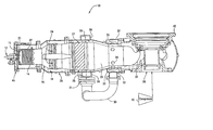
- FIG. 1 is a schematic cross-sectional illustration of a combustor forming a part of a gas turbine and constructed in accordance with the present invention
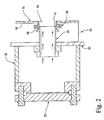
- FIG. 2 is a detailed illustration of the injection manifold and the bypass injection scheme of the present invention
- FIG. 3 illustrates another embodiment of the invention wherein a catalytic reactor is removed from the combustor
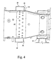
- FIG. 4 shows a section of the combustor casing, of FIG. 1, having an array of openings for extracting compressor discharge air.
- a gas turbine includes a compressor section, a combustion section and a turbine section.
- the compressor section is driven by the turbine section typically through a common shaft connection.
- the combustion section typically includes a circular array of circumferentially spaced combustors. A fuel/air mixture is burned in each combustor to produce the hot energetic gas, which flows through a transition piece to the turbine section.
- combustor For purposes of the present description, only one combustor is discussed and illustrated, it being appreciated that all of the other combustors arranged about the turbine are substantially identical to one another.
- FIG. 1 there is shown a combustor generally indicated at 10 for a gas turbine including a fuel injector assembly 12 having a single nozzle or a plurality of fuel nozzles (not shown), a cylindrical body 16 with an inner liner 15 , and a casing 20 enclosing the body 16 thereby defining a passageway 18 , preferably an annulus 18 therebetween.
- An ignition device (not shown) is provided and preferably comprises an electrically energized spark plug.
- Discharge air received from a compressor 40 via an inlet duct 38 flows through the annulus 18 and enters the body 16 through a plurality of holes 22 provided on the body 16 .
- Compressor discharge air enters body 16 under a pressure differential across the cap assembly 21 to mix with fuel from the fuel injector assembly 12 .
- the mixture is burnt by the pre-burner assembly 11 .
- Combustion occurs in a first combustion chamber or first reaction zone 14 within the body 16 thus raising the temperature of the combustion gases to a sufficient level for the catalyst 27 to react.
- Combustion air from the first combustion chamber 14 flows through a main fuel premixer (MFP) assembly 24 and then through catalyst 27 into the main combustion chamber or main reaction zone 29 for combustion.
- MFP main fuel premixer
- Additional fuel is pumped into the MFP assembly to mix with hot gases, exiting the first combustion chamber 14 , thus producing a combustion reaction in the main combustion chamber 29 , whereby the hot gases of combustion pass through a transition piece 36 to drive the turbine (an inlet section of which is shown at 42 ).
- a predetermined amount of the compressor discharge air is extracted from the annulus 18 into a manifold 26 via an array of openings 25 (FIG. 4) located in casing 20 and leading into an opening 28 which sealingly mates with one end of a bypass conduit 30 , while a second end of conduit 30 leads into an injection manifold 32 .
- a valve 31 regulates the amount of air supplied to manifold 32 .
- Air received in manifold 32 is injected by a plurality of injection tubes 33 into body 16 , bypassing catalyst 27 .
- Each of the injection tubes 33 and manifold 32 are located substantially in a common axial plane. Further, each injection tube opens into body 16 through apertures 34 (FIG. 2).
- Removable flange covers 23 are provided on the injection manifold in substantial radial alignment with the respective injector tubes 33 affording access to the tubes.
- the injection tubes are installed from the outside of the injection manifold at circumferentially spaced locations about the casing and the liner through flange covers.
- Members 35 and 39 (FIG. 2) cooperate to secure each injection tube 33 to body 16 in a floating seal to provide a sealingly tight connection.
- injected air cools the reaction and quenches the combustion process.
- FIG. 3 a second embodiment is illustrated wherein like elements as in the combustor of FIG. 1 are indicated by like reference numerals preceded by the prefix “1”.
- the combustor 110 comprises a combustion chamber or reaction zone 114 where main combustion occurs. Catalyst 27 and MFP assembly 24 are absent in this embodiment.
- compressor discharge air from annulus 118 flows into manifold 126 , and from manifold 126 via conduit 130 flows into body 116 through injection tubes 133 bypassing the combustion chamber 114 . Further, the amount of fuel supplied to mix with compressor discharge air is greater than the amount supplied in the presence of a catalyst.
- combustion chamber 114 need not necessarily lie in close proximity to the fuel injector assembly 112 . Rather it may be located within body 116 between end member 143 and manifold 132 . Likewise, manifold 132 may be appropriately located along casing 120 to inject air into body 116 provided the combustion chamber is bypassed in order to quench the combustion process.
- the present invention has the advantages of maximizing the effectiveness of the catalytic reaction, thereby increasing the efficiency of the combustor.
- the present invention further provides a simple means of controlling the combustion process.
Landscapes
- Engineering & Computer Science (AREA)
- Chemical & Material Sciences (AREA)
- Chemical Kinetics & Catalysis (AREA)
- Combustion & Propulsion (AREA)
- Mechanical Engineering (AREA)
- General Engineering & Computer Science (AREA)
Abstract
Description
- The present invention relates to gas turbines, and more particularly, relates to a bypass air injection apparatus and method to increase the effectiveness of the combustor by quenching the combustion process.
- Gas turbine manufacturers are currently involved in research and engineering programs to produce new gas turbines that will operate at high efficiency without producing undesirable air polluting emissions. The primary air polluting emissions usually produced by gas turbines burning conventional hydrocarbon fuels are oxides of nitrogen, carbon monoxide and unburned hydrocarbons.
- Catalytic reactors are generally used in gas turbines to control the amount of pollutants as a catalytic reactor burns a fuel and air mixture at lower temperatures, thus reduces pollutants released during combustion. As a catalytic reactor ages, the equivalence ratio (actual fuel/air ratio divided by the stochiometric fuel/air ratio for combustion) of the reactants traveling through the reactor needs to be increased in order to maximize the effectiveness of the reactor. Thus, there is a need to compensate for the degradation of the catalytic reactor.
- Accordingly, the present invention is directed to a bypass air injection apparatus and method to compensate for the degradation of a catalytic reactor and to increase combustor efficiency by extracting compressor discharge air prior to its entry into a combustion or reaction zone of the combustor, and re-injecting the extracted compressor discharge air into the combustor bypassing the catalytic reactor using a plurality of injection tubes located substantially in a common axial plane with an injection manifold. Compressor discharge air is received by the combustor in a first combustion chamber through a passageway, preferably an annulus defined between a combustor body with an inner liner and a casing enclosing the body. The first combustion chamber includes a pre-burner stage where fuel is mixed with compressor discharge air for combustion, thus raising the temperature of the hot gases sufficiently to sustain a reaction with the catalyst disposed downstream of the first combustion chamber. Hot gases flowing out of the first combustion chamber pass through a main fuel premixer (MFP) assembly for combustion in a main combustion chamber disposed downstream of the catalyst.
- A predetermined amount of compressor discharge air, flowing through the annulus, and prior to reception in the first combustion chamber, is extracted into a manifold. The extraction manifold is disposed adjacent to an array of openings located in the casing enabling compressor discharge air to flow from the annulus into the extraction manifold. A bypass conduit connects the extraction manifold to an injection manifold. The injection manifold lies in communication with a plurality of injection tubes for injecting the extracted air into the combustor body bypassing the catalyst. As noted above, each injection tube and the injection manifold are disposed in a substantially common axial plane. Removable flange covers are provided on the injection manifold in substantial radial alignment with the respective injector tubes affording access to the tubes. The injection tubes are installed from the outside of the injection manifold at circumferentially spaced locations about the casing and the liner through flange covers. A bypass air(i.e., extracted air) path is therefore provided to bridge the backside cooling airflow annulus disposed between the combustor casing and the combustion liner.
- In another embodiment, the combustor includes only one combustion chamber. Thus, the combustor is devoid of the catalyst and the MFP assembly. Here, main combustion occurs at the pre-burner stage where a greater amount of fuel is mixed with air in order for combustion to occur.
- In one aspect, the present invention provides a combustor for a gas turbine having a combustor body with an inner liner; a casing enclosing the body and defining a passageway therebetween for carrying compressor discharge air; a combustion chamber within the body for combustion of fuel and air; a first manifold for extracting a predetermined amount of compressor discharge air from the passageway; a second manifold for receiving the extracted air and supplying the extracted air into the body at a location bypassing the combustion chamber; and a plurality of injection tubes in communication with the second manifold for injecting the extracted air into the body to quench combustion, the injection tubes and the second manifold being disposed in a substantially common axial plane. The combustor further includes an array of openings disposed in the casing to permit the compressor discharge air to flow through the openings into the first manifold; and a conduit for supplying the extracted air from the first manifold to the second manifold. The second manifold preferably includes an access flange for each of the injection tubes. Preferably, the injection tubes are equally spaced from one another about the second manifold. The first and second ends of the conduit terminate in the first and second manifolds, respectively. The conduit includes a control valve to regulate air flowing from the first manifold to the second manifold. The first and second manifolds are preferably disposed about an outer surface of the casing.
- In another aspect, the present invention provides a combustor for a gas turbine including a combustor body with an inner liner; a casing enclosing the body and defining a passageway therebetween for carrying compressor discharge air; a catalytic reactor disposed in the body for controlling pollutants released during combustion; a first manifold for extracting a predetermined amount of compressor discharge air from the passageway; a second manifold for receiving the extracted air and supplying the extracted air to the body at a location bypassing the catalytic reactor; and a plurality of injection tubes in communication with the second manifold for injecting the extracted air into the body, the injection tubes and the second manifold being disposed in a substantially common axial plane.
- In another aspect, the present invention provides a gas turbine having a compressor section for pressurizing air; a combustor for receiving the pressurized air; and a turbine section for receiving hot gases of combustion from the combustor, the combustor including a combustor body with an inner liner, a casing enclosing the body and defining a passageway therebetween for carrying compressor discharge air, a combustion chamber within the body for combustion of fuel and air, a first manifold for extracting a predetermined amount of compressor discharge air from the passageway, a second manifold for receiving the extracted air and supplying the extracted air into the body at a location bypassing the combustion chamber, and a plurality of injection tubes in communication with the second manifold for injecting the extracted air to the body to quench combustion, the injection tubes and the second manifold are disposed in a substantially common axial plane.
- In yet another aspect, the present invention provides a method for quenching combustion by extracting a predetermined amount of compressor discharge air, before the air flows into the reactor, from the passageway into the first manifold; supplying the extracted air from the first manifold to the second manifold via the conduit; injecting the extracted air received by the second manifold into the body at a location along the body bypassing the reactor using an array of injection tubes; and disposing the injection tubes and the second manifold in a substantially common axial plane.
- FIG. 1 is a schematic cross-sectional illustration of a combustor forming a part of a gas turbine and constructed in accordance with the present invention;
- FIG. 2 is a detailed illustration of the injection manifold and the bypass injection scheme of the present invention;
- FIG. 3 illustrates another embodiment of the invention wherein a catalytic reactor is removed from the combustor; and
- FIG. 4 shows a section of the combustor casing, of FIG. 1, having an array of openings for extracting compressor discharge air.
- As is well known, a gas turbine includes a compressor section, a combustion section and a turbine section. The compressor section is driven by the turbine section typically through a common shaft connection. The combustion section typically includes a circular array of circumferentially spaced combustors. A fuel/air mixture is burned in each combustor to produce the hot energetic gas, which flows through a transition piece to the turbine section. For purposes of the present description, only one combustor is discussed and illustrated, it being appreciated that all of the other combustors arranged about the turbine are substantially identical to one another.
- Referring now to FIG. 1, there is shown a combustor generally indicated at 10 for a gas turbine including a
fuel injector assembly 12 having a single nozzle or a plurality of fuel nozzles (not shown), acylindrical body 16 with aninner liner 15, and acasing 20 enclosing thebody 16 thereby defining apassageway 18, preferably anannulus 18 therebetween. An ignition device (not shown) is provided and preferably comprises an electrically energized spark plug. Discharge air received from acompressor 40 via aninlet duct 38 flows through theannulus 18 and enters thebody 16 through a plurality ofholes 22 provided on thebody 16. Compressor discharge air entersbody 16 under a pressure differential across thecap assembly 21 to mix with fuel from thefuel injector assembly 12. The mixture is burnt by thepre-burner assembly 11. Combustion occurs in a first combustion chamber orfirst reaction zone 14 within thebody 16 thus raising the temperature of the combustion gases to a sufficient level for thecatalyst 27 to react. Combustion air from thefirst combustion chamber 14 flows through a main fuel premixer (MFP)assembly 24 and then throughcatalyst 27 into the main combustion chamber ormain reaction zone 29 for combustion. Additional fuel is pumped into the MFP assembly to mix with hot gases, exiting thefirst combustion chamber 14, thus producing a combustion reaction in themain combustion chamber 29, whereby the hot gases of combustion pass through atransition piece 36 to drive the turbine (an inlet section of which is shown at 42). - A predetermined amount of the compressor discharge air is extracted from the
annulus 18 into amanifold 26 via an array of openings 25 (FIG. 4) located incasing 20 and leading into anopening 28 which sealingly mates with one end of abypass conduit 30, while a second end ofconduit 30 leads into aninjection manifold 32. Avalve 31 regulates the amount of air supplied tomanifold 32. Air received inmanifold 32 is injected by a plurality ofinjection tubes 33 intobody 16, bypassingcatalyst 27. Each of theinjection tubes 33 andmanifold 32 are located substantially in a common axial plane. Further, each injection tube opens intobody 16 through apertures 34 (FIG. 2). Removable flange covers 23 are provided on the injection manifold in substantial radial alignment with therespective injector tubes 33 affording access to the tubes. The injection tubes are installed from the outside of the injection manifold at circumferentially spaced locations about the casing and the liner through flange covers.Members 35 and 39 (FIG. 2) cooperate to secure eachinjection tube 33 tobody 16 in a floating seal to provide a sealingly tight connection. Thus, injected air cools the reaction and quenches the combustion process. - Referring to FIG. 3, a second embodiment is illustrated wherein like elements as in the combustor of FIG. 1 are indicated by like reference numerals preceded by the prefix “1”. Here, the
combustor 110 comprises a combustion chamber orreaction zone 114 where main combustion occurs.Catalyst 27 andMFP assembly 24 are absent in this embodiment. Here, compressor discharge air fromannulus 118 flows intomanifold 126, and frommanifold 126 viaconduit 130 flows intobody 116 throughinjection tubes 133 bypassing thecombustion chamber 114. Further, the amount of fuel supplied to mix with compressor discharge air is greater than the amount supplied in the presence of a catalyst. It will be appreciated that the location of thecombustion chamber 114 need not necessarily lie in close proximity to thefuel injector assembly 112. Rather it may be located withinbody 116 betweenend member 143 andmanifold 132. Likewise, manifold 132 may be appropriately located along casing 120 to inject air intobody 116 provided the combustion chamber is bypassed in order to quench the combustion process. - Thus, the present invention has the advantages of maximizing the effectiveness of the catalytic reaction, thereby increasing the efficiency of the combustor. The present invention further provides a simple means of controlling the combustion process.
- While the invention has been described in connection with what is presently considered to be the most practical and preferred embodiment, it is to be understood that the invention is not to be limited to the disclosed embodiment, but on the contrary, is intended to cover various modifications and equivalent arrangements included within the spirit and scope of the appended claims.
Claims (20)
Priority Applications (1)
| Application Number | Priority Date | Filing Date | Title |
|---|---|---|---|
| US10/205,228 US6568188B2 (en) | 2001-04-09 | 2002-07-26 | Bypass air injection method and apparatus for gas turbines |
Applications Claiming Priority (2)
| Application Number | Priority Date | Filing Date | Title |
|---|---|---|---|
| US09/828,471 US6449956B1 (en) | 2001-04-09 | 2001-04-09 | Bypass air injection method and apparatus for gas turbines |
| US10/205,228 US6568188B2 (en) | 2001-04-09 | 2002-07-26 | Bypass air injection method and apparatus for gas turbines |
Related Parent Applications (1)
| Application Number | Title | Priority Date | Filing Date |
|---|---|---|---|
| US09/828,471 Division US6449956B1 (en) | 2001-04-09 | 2001-04-09 | Bypass air injection method and apparatus for gas turbines |
Publications (2)
| Publication Number | Publication Date |
|---|---|
| US20020184871A1 true US20020184871A1 (en) | 2002-12-12 |
| US6568188B2 US6568188B2 (en) | 2003-05-27 |
Family
ID=25251902
Family Applications (2)
| Application Number | Title | Priority Date | Filing Date |
|---|---|---|---|
| US09/828,471 Expired - Lifetime US6449956B1 (en) | 2001-04-09 | 2001-04-09 | Bypass air injection method and apparatus for gas turbines |
| US10/205,228 Expired - Lifetime US6568188B2 (en) | 2001-04-09 | 2002-07-26 | Bypass air injection method and apparatus for gas turbines |
Family Applications Before (1)
| Application Number | Title | Priority Date | Filing Date |
|---|---|---|---|
| US09/828,471 Expired - Lifetime US6449956B1 (en) | 2001-04-09 | 2001-04-09 | Bypass air injection method and apparatus for gas turbines |
Country Status (1)
| Country | Link |
|---|---|
| US (2) | US6449956B1 (en) |
Cited By (2)
| Publication number | Priority date | Publication date | Assignee | Title |
|---|---|---|---|---|
| DE102005039247B4 (en) * | 2004-09-02 | 2011-08-18 | General Electric Co., N.Y. | Air injection with fixed concentric dilution and variable bypass flow for burners |
| WO2015122992A1 (en) * | 2014-02-13 | 2015-08-20 | United Technologies Corporation | Nacelle ventilation manifold |
Families Citing this family (23)
| Publication number | Priority date | Publication date | Assignee | Title |
|---|---|---|---|---|
| US7076568B2 (en) * | 1997-10-14 | 2006-07-11 | Alacritech, Inc. | Data communication apparatus for computer intelligent network interface card which transfers data between a network and a storage device according designated uniform datagram protocol socket |
| JP2002317650A (en) * | 2001-04-24 | 2002-10-31 | Mitsubishi Heavy Ind Ltd | Gas turbine combustor |
| JP2003329244A (en) * | 2002-05-14 | 2003-11-19 | Mitsubishi Heavy Ind Ltd | Gas turbine combustor and combustion controlling method |
| US7043921B2 (en) * | 2003-08-26 | 2006-05-16 | Honeywell International, Inc. | Tube cooled combustor |
| JP2005171795A (en) * | 2003-12-09 | 2005-06-30 | Mitsubishi Heavy Ind Ltd | Gas turbine combustion equipment |
| US20070151257A1 (en) * | 2006-01-05 | 2007-07-05 | Maier Mark S | Method and apparatus for enabling engine turn down |
| US20090053036A1 (en) * | 2007-08-24 | 2009-02-26 | General Electric Company | Systems and Methods for Extending Gas Turbine Emissions Compliance |
| US7921653B2 (en) * | 2007-11-26 | 2011-04-12 | General Electric Company | Internal manifold air extraction system for IGCC combustor and method |
| US20100223930A1 (en) * | 2009-03-06 | 2010-09-09 | General Electric Company | Injection device for a turbomachine |
| US8281601B2 (en) * | 2009-03-20 | 2012-10-09 | General Electric Company | Systems and methods for reintroducing gas turbine combustion bypass flow |
| RU2506499C2 (en) * | 2009-11-09 | 2014-02-10 | Дженерал Электрик Компани | Fuel atomisers of gas turbine with opposite swirling directions |
| US20110162378A1 (en) * | 2010-01-06 | 2011-07-07 | General Electric Company | Tunable transition piece aft frame |
| RU2010101978A (en) * | 2010-01-15 | 2011-07-20 | Дженерал Электрик Компани (US) | GAS TURBINE CONNECTION UNIT |
| US8276386B2 (en) | 2010-09-24 | 2012-10-02 | General Electric Company | Apparatus and method for a combustor |
| US8966906B2 (en) * | 2011-09-28 | 2015-03-03 | General Electric Company | System for supplying pressurized fluid to a cap assembly of a gas turbine combustor |
| US8695352B2 (en) * | 2012-07-12 | 2014-04-15 | Solar Turbines Inc. | Baffle assembly for bleed air system of gas turbine engine |
| US9500367B2 (en) | 2013-11-11 | 2016-11-22 | General Electric Company | Combustion casing manifold for high pressure air delivery to a fuel nozzle pilot system |
| US10788212B2 (en) * | 2015-01-12 | 2020-09-29 | General Electric Company | System and method for an oxidant passageway in a gas turbine system with exhaust gas recirculation |
| US20170191373A1 (en) | 2015-12-30 | 2017-07-06 | General Electric Company | Passive flow modulation of cooling flow into a cavity |
| US10337411B2 (en) | 2015-12-30 | 2019-07-02 | General Electric Company | Auto thermal valve (ATV) for dual mode passive cooling flow modulation |
| US10337739B2 (en) | 2016-08-16 | 2019-07-02 | General Electric Company | Combustion bypass passive valve system for a gas turbine |
| US10738712B2 (en) | 2017-01-27 | 2020-08-11 | General Electric Company | Pneumatically-actuated bypass valve |
| US10712007B2 (en) | 2017-01-27 | 2020-07-14 | General Electric Company | Pneumatically-actuated fuel nozzle air flow modulator |
Family Cites Families (8)
| Publication number | Priority date | Publication date | Assignee | Title |
|---|---|---|---|---|
| US4047877A (en) * | 1976-07-26 | 1977-09-13 | Engelhard Minerals & Chemicals Corporation | Combustion method and apparatus |
| US4255927A (en) * | 1978-06-29 | 1981-03-17 | General Electric Company | Combustion control system |
| US5207053A (en) * | 1991-05-15 | 1993-05-04 | United Technologies Corporation | Method and system for staged rich/lean combustion |
| KR930013441A (en) * | 1991-12-18 | 1993-07-21 | 아더 엠.킹 | Gas turbine combustor with multiple combustors |
| US5461864A (en) * | 1993-12-10 | 1995-10-31 | Catalytica, Inc. | Cooled support structure for a catalyst |
| GB9609317D0 (en) * | 1996-05-03 | 1996-07-10 | Rolls Royce Plc | A combustion chamber and a method of operation thereof |
| SE9602688L (en) * | 1996-07-08 | 1998-01-09 | Volvo Ab | Catalytic combustion chamber, and method for igniting and controlling the catalytic combustion chamber |
| US5924276A (en) * | 1996-07-17 | 1999-07-20 | Mowill; R. Jan | Premixer with dilution air bypass valve assembly |
-
2001
- 2001-04-09 US US09/828,471 patent/US6449956B1/en not_active Expired - Lifetime
-
2002
- 2002-07-26 US US10/205,228 patent/US6568188B2/en not_active Expired - Lifetime
Cited By (4)
| Publication number | Priority date | Publication date | Assignee | Title |
|---|---|---|---|---|
| DE102005039247B4 (en) * | 2004-09-02 | 2011-08-18 | General Electric Co., N.Y. | Air injection with fixed concentric dilution and variable bypass flow for burners |
| WO2015122992A1 (en) * | 2014-02-13 | 2015-08-20 | United Technologies Corporation | Nacelle ventilation manifold |
| US10443429B2 (en) | 2014-02-13 | 2019-10-15 | United Technologies Corporation | Gas turbine nacelle ventilation manifold having a circumferential varying cross-sectional area |
| US10526910B2 (en) | 2014-02-13 | 2020-01-07 | United Technologies Corporation | Gas turbine engine nacelle ventilation manifold for cooling accessories |
Also Published As
| Publication number | Publication date |
|---|---|
| US6568188B2 (en) | 2003-05-27 |
| US20020144507A1 (en) | 2002-10-10 |
| US6449956B1 (en) | 2002-09-17 |
Similar Documents
| Publication | Publication Date | Title |
|---|---|---|
| US6449956B1 (en) | Bypass air injection method and apparatus for gas turbines | |
| US7000396B1 (en) | Concentric fixed dilution and variable bypass air injection for a combustor | |
| US20060016195A1 (en) | Bypass and injection method and apparatus for gas turbines | |
| US6192688B1 (en) | Premixing dry low nox emissions combustor with lean direct injection of gas fule | |
| US5894720A (en) | Low emissions combustion system for a gas turbine engine employing flame stabilization within the injector tube | |
| US5161366A (en) | Gas turbine catalytic combustor with preburner and low nox emissions | |
| US5850731A (en) | Catalytic combustor with lean direct injection of gas fuel for low emissions combustion and methods of operation | |
| US6826913B2 (en) | Airflow modulation technique for low emissions combustors | |
| US4112676A (en) | Hybrid combustor with staged injection of pre-mixed fuel | |
| US6848260B2 (en) | Premixed pilot burner for a combustion turbine engine | |
| US6684642B2 (en) | Gas turbine engine having a multi-stage multi-plane combustion system | |
| US20010049932A1 (en) | Premixing dry low NOx emissions combustor with lean direct injection of gas fuel | |
| EP2578942A2 (en) | Apparatus for head end direct air injection with enhanced mixing capabaliites | |
| US8256226B2 (en) | Radial lean direct injection burner | |
| EP0071419A1 (en) | Combustion apparatus with reduced nitrogen oxide emission | |
| CN113864818B (en) | Combustor air flow path | |
| US20180340689A1 (en) | Low Profile Axially Staged Fuel Injector | |
| RU2755240C2 (en) | Burner for combustion chamber of gas turbine power plant, combustion chamber of gas turbine power plant containing such burner, and gas turbine power plant containing such combustion chamber |
Legal Events
| Date | Code | Title | Description |
|---|---|---|---|
| FEPP | Fee payment procedure |
Free format text: PAYOR NUMBER ASSIGNED (ORIGINAL EVENT CODE: ASPN); ENTITY STATUS OF PATENT OWNER: LARGE ENTITY |
|
| STCF | Information on status: patent grant |
Free format text: PATENTED CASE |
|
| AS | Assignment |
Owner name: CATALYTICA ENERGY SYSTEMS, INC., ARIZONA Free format text: ASSIGNMENT OF ASSIGNORS INTEREST;ASSIGNORS:BETTA, RALPH DALLA;LUNDBERG, KARE;CARON, TIMOTHY;REEL/FRAME:014462/0058;SIGNING DATES FROM 20040127 TO 20040217 |
|
| AS | Assignment |
Owner name: KAWASAKI JUKOGYO KABUSHIKI KAISHA, JAPAN Free format text: ASSIGNMENT OF ASSIGNORS INTEREST;ASSIGNOR:CATALYTICA ENERGY SYSTEMS, INC.;REEL/FRAME:018454/0648 Effective date: 20060921 |
|
| FPAY | Fee payment |
Year of fee payment: 4 |
|
| AS | Assignment |
Owner name: KAWASAKI JUKOGYO KABUSHIKI KAISHA, JAPAN Free format text: ASSIGNMENT OF ASSIGNORS INTEREST;ASSIGNOR:CATALYTICA ENERGY SYSTEMS, INC.;REEL/FRAME:018545/0991 Effective date: 20060921 Owner name: KAWASAKI JUKOGYO KABUSHIKI KAISHA, JAPAN Free format text: ASSIGNMENT OF ASSIGNORS INTEREST;ASSIGNOR:CATALYTICA ENERGY SYSTEMS, INC.;REEL/FRAME:018545/0987 Effective date: 20060921 |
|
| AS | Assignment |
Owner name: KAWASAKI JUKOGYO KABUSHIKI KAISHA, JAPAN Free format text: ASSIGNMENT OF ASSIGNORS INTEREST;ASSIGNOR:CATALYTICA ENERGY SYSTEMS, INC.;REEL/FRAME:018545/0995 Effective date: 20060921 |
|
| AS | Assignment |
Owner name: KAWASAKI JUKOGYO KABUSHIKI KAISHA, JAPAN Free format text: ASSIGNMENT OF ASSIGNORS INTEREST;ASSIGNOR:CATALYTICA ENERGY SYSTEMS, INC.;REEL/FRAME:018552/0166 Effective date: 20060921 Owner name: KAWASAKI JUKOGYO KABUSHIKI KAISHA, JAPAN Free format text: ASSIGNMENT OF ASSIGNORS INTEREST;ASSIGNOR:CATALYTICA ENERGY SYSTEMS, INC.;REEL/FRAME:018552/0170 Effective date: 20060921 Owner name: KAWASAKI JUKOGYO KABUSHIKI KAISHA, JAPAN Free format text: ASSIGNMENT OF ASSIGNORS INTEREST;ASSIGNOR:CATALYTICA ENERGY SYSTEMS, INC.;REEL/FRAME:018552/0162 Effective date: 20060921 |
|
| FPAY | Fee payment |
Year of fee payment: 8 |
|
| FPAY | Fee payment |
Year of fee payment: 12 |