US20020184868A1 - Guard and dolly for line trimming apparatus - Google Patents
Guard and dolly for line trimming apparatus Download PDFInfo
- Publication number
- US20020184868A1 US20020184868A1 US10/068,051 US6805102A US2002184868A1 US 20020184868 A1 US20020184868 A1 US 20020184868A1 US 6805102 A US6805102 A US 6805102A US 2002184868 A1 US2002184868 A1 US 2002184868A1
- Authority
- US
- United States
- Prior art keywords
- dolly
- wheel
- trimming apparatus
- line trimming
- receptacle
- Prior art date
- Legal status (The legal status is an assumption and is not a legal conclusion. Google has not performed a legal analysis and makes no representation as to the accuracy of the status listed.)
- Granted
Links
Images


Classifications
-
- A—HUMAN NECESSITIES
- A01—AGRICULTURE; FORESTRY; ANIMAL HUSBANDRY; HUNTING; TRAPPING; FISHING
- A01D—HARVESTING; MOWING
- A01D34/00—Mowers; Mowing apparatus of harvesters
- A01D34/001—Accessories not otherwise provided for
-
- A—HUMAN NECESSITIES
- A01—AGRICULTURE; FORESTRY; ANIMAL HUSBANDRY; HUNTING; TRAPPING; FISHING
- A01D—HARVESTING; MOWING
- A01D2101/00—Lawn-mowers
Definitions
- This invention relates to line trimming devices and more particularly, to a guard and a dolly for receiving and mounting a line trimming device or apparatus and mowing, edging and trimming a lawn.
- the guard of this invention includes a shaped debris-deflection device having a tab-and-slot opening for receiving and mounting a corresponding coupling flange attached to the line trimming apparatus motor in a free-hand trimming configuration.
- a universal dolly is broadly characterized by a dolly frame shaped and adapted for receiving a gasoline-powered or electric line trimmer for various lawn mowing, trimming and edging functions.
- the dolly is characterized by a frame base and plate having front, side and rear wheel receptacles for selectively receiving brackets which rotatably mount the wheels.
- three wheels are attached by means of the brackets to the side and the center rear wheel receptacle locations for supporting the dolly frame and line trimmer in rolling relationship in a horizontal plane for operation of the line trimmer in a mowing configuration.
- the wheels in the side wheel receptacles are rearranged in the outside rear wheel receptacles to support the dolly frame and line trimmer in a horizontal plane for operation of the line trimmer in a trimming configuration.
- the wheels are attached to the front wheel receptacles only, to support the dolly frame and line trimmer in a vertical plane for operation of the line trimmer in an edging configuration.
- the line trimmer can be attached to a guard without wheels for use as a free-hand trimmer, as well as a universal dolly for disposition in mowing, trimming and edging configurations.
- the line trimming apparatus is fitted with a motor coupling flange that engages a corresponding tab-and-slot opening in the guard and dolly frame, respectively, to removably mount the line trimming device on the free-hand trimmer and universal dolly, respectively.
- Line edgers and trimmers have long been known and used for trimming and edging lawns and other grassy and weed-infested areas. Typical of these devices are the devices disclosed in U.S. Pat. Nos. 4,047,299, and 3,859,776. Accessory devices are also used in connection with “edgers” and line trimmers and typical of these devices is the attachment described in U.S. Pat. No. 3,587,749, dated Jun. 28, 1971, to Gerald P. Sauer, entitled “A Lawn Edger Attachment For A Power Saw”. In this patent the saw blade of an electric power saw is replaced with a two-side ground cutter blade and the power saw is attached to and carried by a wheeled carrier.
- a shoe on the power saw is attached to a base plate of the carrier and the shoe and cutter blade are adjustable relative to each other, in order to adjust the blade cutting height.
- a pivotally-mounted handle by which the carrier may be pushed, carries a switch for stopping and starting the electric motor which drives the saw.
- the carrier base plate is supported on three wheels for ease of turning and maneuvering.
- An “Attachment For Line Trimmer” is disclosed in U.S. Pat. No. 4,224,784, dated Sep. 30, 1980, to Lee A. Hansen. This device is designed to convert a line trimmer to an edge trimmer and includes a collar with support legs attached thereto and wheels attached to the support legs.
- a U-shaped brace extends between the support legs, in order to hold the support legs at an angle with respect to each other.
- the collar is placed loosely around the handle of an existing line trimmer and the line trimmer is inverted, in order to present the spool thereof perpendicular to the ground.
- the legs are inserted into the collar and the collar is then secured to the handle, with the head of the line trimmer located between the ends of the U-shaped brace.
- the patent discloses a balanced, self-propelled and manually guided lawn edge in which an edging cutter blade is positioned near the inner side and rearwardly of the larger of two traction wheels of unequal diameter, mounted on a common drive axle.
- the smaller traction wheel can be axially adjusted relative to the larger wheel to regulate the angle of cut adjacent to a side wall or a curbing.
- a “Dolly For Lawn Trimmer and Combination Thereof” is disclosed in U.S. Pat. No. 4,442,659, dated Apr. 17, 1984, to H. J. Enbusk.
- the patent details a trimmer supported on a dolly, each of which trimmer and dolly is provided with a handle.
- the operator holds the dolly handle in one hand and the trimmer handle in the other hand and the trimmer is pivotally connected to the dolly, whereby movement of the handle of the trimmer relative to the dolly handle changes the approach angle of the trimmer relative to the movement of the dolly.
- the pivoted connection is positioned forward of the dolly wheels, whereby raising and lowering the dolly handle effects lowering and raising of the trimmer and the corresponding depth of cut.
- the pivoted connection includes adjustment means to adjust the positions of the trimmer relative to the dolly.
- the device includes a frame supported on at least three wheels, which frame securely carries one or more rechargeable wet-cell batteries, as well as a pivotally-mounted sub-assembly having a heavy duty, series-wound drive motor, a rigid edger blade mounted on the drive motor output shaft and a blade guard. Re-charging may be accomplished by interconnection to a conventional automotive charging system, a battery charger or to a 115-volt power source.
- the blade is positioned to rotate in a plane generally perpendicular to the ground and a blade-positioning lever is pivotally attached to the main guide handle for vertical adjustment of the blade.
- a drive motor on-off switch attachable to the handle is also provided and a removable cover may be provided for protecting the battery energizers.
- One or more of the wheels may also include drive means for locomotion.
- the edger is provided with a rotatable cutting blade for trimming grass, weeds and the like.
- the cutting blade is driven by a motor mounted within a motor housing which is, in turn, supported for rotation about a longitudinal axis between a front wheel assembly and a rear wheel assembly.
- a locking mechanism is carried by the motor housing and is provided with a pair of spring-biased lugs normally received into locking recesses in the front and rear wheel assemblies to lock the motor housing into a selected rotational position and thereby lock the cutting blade at a selected angular orientation.
- An object of this invention is to provide a free-hand line trimming apparatus characterized by a guard having a tab-and-slot opening and a line trimming apparatus with a coupling flange provided thereon for engaging the tab-and-slot opening and coupling the apparatus to the guard.
- Another object of this invention to provide a new and improved dolly for a line trimming apparatus, which dolly is characterized by a frame for removably receiving the motor, body or housing of a line trimmer and having square or star-shaped wheel-carrying front, rear and side receptacles for adapting the line trimmer to edge, trim and mow grass and cut weeds.
- Yet another object of the invention is to provide a universal dolly for receiving and adapting a line trimming apparatus to edge, mow and trim grass and weeds, which universal dolly includes a typically metal or plastic dolly frame for removably receiving the frame, body or motor housing of a line trimming apparatus and wheel mount brackets fitted with wheels, selectively positioned on the dolly frame for converting the dolly into trimming, mowing and edging configurations, respectively.,
- Still another object of this invention is to provide a universal dolly for receiving and mounting a gasoline or an electric-powered line trimming apparatus, which dolly is characterized by removable wheels selectively arranged on the dolly by means of L-shaped wheel brackets, wherein the line trimming apparatus can be utilized to mow, edge or trim a lawn or yard by rearranging the wheel location and operation of the line trimming apparatus.
- Yet another object of this invention is to provide a dolly for receiving and mounting an electrically-operated line trimmer by means of a tab-and-slot coupling mechanism and a sliding collar, which dolly includes removable front, side and rear wheels selectively arranged on the dolly to facilitate various configurations of the dolly and operation of the line trimmer and the dolly to mow, trim and edge a lawn.
- Another object of this invention is to provide a dolly which is characterized by a shaped, typically metal or plastic frame, having frame receptacles and at least two wheels rotatably mounted on the frame receptacles at selected locations, which frame is further provided with a tab-and-slot or bayonet-type opening adapted to receive and mount a line trimmer having a correspondingly-shaped coupling flange, for mowing, trimming and edging a lawn or yard by rotation of the wheels and operation of the selectively-configured dolly and line trimmer.
- Yet another object of this invention is to provide a universal dolly which is characterized by a typically fiberglass, plastic or metal frame and either three wheels or a pair of wheels positioned at selected receptacle locations on the frame, which frame is also fitted with a slotted opening adapted to receive a tabbed motor coupling flange on a line trimmer, such that the line trimmer and dolly cooperate to facilitate edging, mowing and trimming a lawn or yard.
- a still further object of this invention is to provide a new and improved universal dolly having a dolly frame with a bayonet or tab-and-slot opening for removably receiving the coupling flange of a gasoline powered or electric line trimmer, along with a spring-loaded collar for engaging the line trimmer handle and facilitating arrangement of two or three wheels on the dolly frame, such that the line trimmer can be oriented into various configurations for mowing, edging and trimming a lawn or yard by changing the wheel configurations.
- a free-hand line trimming apparatus having a tab and slot locking flange for engaging a correspondingly-shaped tab and slot opening in a guard and removably locking the guard on the line trimming apparatus.
- a wheeled dolly having a shaped frame provided with front, side and rear wheel receptacles and a lock-and-tab type opening, which opening is adapted to receive the like-shaped coupling flange of an electric or gasoline-powered line trimmer and two or three wheels are selectively oriented to mow, edge or trim a lawn by arranging the positions of the wheels on brackets fitted in the frame wheel receptacles.
- the dolly frame mounts two wheels in first and second configurations and three wheels in a third configuration, for receiving the line trimmer and orienting the line trimmer in functional position to edge, trim and mow a lawn, respectively.
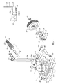
- FIG. 1 is a perspective view of a typical line trimmer and guard embodiment of this invention
- FIG. 2 is a perspective view of a typical line trimmer motor and shaft, fitted with a coupling flange for mounting the guard illustrated in FIG. 1;
- FIG. 3 is a top view of the guard illustrated in FIG. 1;
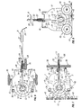
- FIG. 4 is a perspective, exploded view of a preferred universal dolly for receiving and mounting a conventional gasoline-powered or electric line trimmer according to this invention
- FIG. 5 is a side view, partially in section, of a typical bracket flange for mounting wheels on the dolly illustrated in FIG. 4;
- FIG. 6 is a top elevation of the universal dolly illustrated in FIG. 4, assembled with left, right and rear wheels and a guard added to the horizontally-oriented dolly frame and an electric line trimmer mounted on the frame in mowing configuration;
- FIG. 7 is a top elevation of the universal dolly illustrated in FIG. 1, with an electric line trimmer mounted on the dolly and the wheels oriented in outside rear wheel receptacles in trimming configuration;
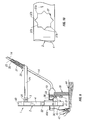
- FIG. 8 is a side elevation of the universal dolly with the wheels mounted on the front wheel receptacles of the vertically-oriented dolly frame, to facilitate an edging function of the electric line trimmer along a sidewalk;
- FIG. 9 is a front elevation of the universal dolly illustrated in FIG. 8, in the edging configuration.
- FIG. 10 is an alternative star-shaped wheel receptacle design for removably securing the wheels to the universal dolly.
- FIGS. 1 - 3 of the drawings a typical line trimming apparatus which can be utilized in both embodiments of this invention is generally illustrated by reference numeral 9 .
- the line trimming apparatus 9 is characterized by a motor 10 , to which is connected a cutting element, spool or attachment 45 a (illustrated in FIG. 9) in conventional fashion.
- a motor coupling flange 11 is typically attached to the motor 10 and the motor coupling flange 11 is characterized by alternating flange slots 12 , which define flange tabs 13 .
- An apparatus shaft or handle 14 typically extends from the top of the motor 10 and is fitted with a shaft collar 21 , a top grip 27 and a middle grip 28 .
- a trigger switch (not illustrated) is typically provided in the top grip 27 in conventional fashion for selectively energizing the motor 10 .
- An electric power cord 29 extends from the top grip 27 for connecting an extension cord (not illustrated) of suitable size and design for supplying power to the motor 10 .
- the guard 19 includes a guard motor coupling opening 15 which is configured with alternating guard coupling slots 16 , that define guard coupling tabs 17 , with a lock tab 18 shaped in two of the guard coupling tabs 17 .
- This design facilitates mounting the motor coupling flange 11 and the attached motor 10 to the guard 19 by inserting the respective flange tabs 13 of the motor coupling flange 11 into the corresponding guard coupling slots 16 of the guard motor coupling opening 15 and twisting the motor 10 and the motor coupling flange 11 , typically in the counterclockwise direction as the line trimming apparatus 9 and the guard 19 are viewed in FIGS.
- the line trimming apparatus 9 is designed to mount on a universal dolly, generally illustrated by reference numeral 1 in FIG. 4 of the drawing.
- the universal dolly 1 is characterized by a shaped dolly frame 2 , having a frame base 4 and a flat frame plate 5 , provided with a dolly motor coupling opening 6 .
- the dolly motor coupling opening 6 is preferably a tab-and-slot or bayonet-type opening having the same design and configuration as the guard motor coupling opening 15 illustrated in FIG. 1, and is fitted with dolly coupling slots 7 , defined by dolly coupling tabs 8 , as illustrated in FIG. 4.
- the dolly frame 2 is designed to receive a line trimming apparatus 9 having a motor 10 , such as the line trimming apparatus 9 illustrated in FIG. 1, which may have either a gasoline motor or an electric motor, as illustrated.
- the motor 10 is fitted with a motor coupling flange 11 , as in the case of the line trimming apparatus 9 illustrated in FIG. 1. As heretofore described with respect to FIG.
- the motor coupling flange 11 has flange slots 12 , defined by flange tabs 13 that are designed to match and fit the dolly motor coupling opening 6 , such that the respective flange tabs 13 of the motor coupling flange 11 initially register with corresponding dolly coupling slots 7 bordering the dolly motor coupling opening 6 and facilitate twisting of the motor 10 and the motor coupling flange 11 to engage the flange tabs 13 with the two lock tabs 18 and three of the dolly coupling tabs 8 , respectively, as heretofore described with respect to FIGS. 1 - 3 .
- the universal dolly 1 is configured as illustrated in FIG.
- the apparatus handle 14 can be removably secured to the brace bracket 25 of the shaft brace 24 when seated in the concave surface 26 of the shaft brace 24 , as the shaft collar 21 is retracted against the shaft collar spring 22 .
- the motor coupling flange 11 is prevented from vibrating or otherwise loosening in the dolly motor coupling opening 6 , to maintain the line trimming apparatus 9 securely on the dolly frame 2 of the universal dolly 1 .
- Each wheel mount bracket 33 has a bracket flange 34 fitted with a flange opening 35 , for receiving a wheel bolt 31 and a nut 3 , and securing each of the respective wheels 30 to a corresponding wheel mount bracket 33 .
- the wheel mount brackets 33 are generally shaped in an “L” configuration, wherein a stub axle 38 extends from the bracket flange 34 and may be inserted in the respective front wheel receptacles 36 , side wheel receptacles 32 and rear wheel receptacles 40 , provided in the frame base 4 of the dolly frame 2 as further illustrated in FIG. 4.
- the stub axles 38 of the respective wheel mount brackets 33 are inserted in square front wheel receptacles 36 , side wheel receptacles 32 and rear wheel receptacles 40 and may be provided with a conventional spring-loaded axle lock ball 39 , which fits in a corresponding ball groove or recess 39 a , located in the frame base 4 of the dolly frame 2 .
- the opening in the frame base 4 of the dolly frame 2 which receives the stub axle 38 may be a star receptacle 37 , having star points 37 a defined by star slots 37 b , for receiving the square stub axle 38 , as illustrated in FIGS. 10 and 11A- 11 C.
- the stub axle 38 can be fitted into the respective star slots 37 b of the star receptacle 37 to position the corresponding wheel mount brackets 33 and wheels 30 in any desired height on the dolly frame 2 , as further illustrated in FIGS. 11 A- 11 C.
- the axle lock ball 39 may be provided at one corner of the stub axle 38 as illustrated in FIG. 11, to facilitate engaging a corresponding ball groove 39 a provided in the frame base 4 , as illustrated in FIGS. 11 A- 11 C.
- the wheels 30 are arranged on the dolly frame 2 with two of the wheels 30 disposed in opposite side wheel receptacles 32 by operation of the stub axle 38 in the wheel mount brackets 33 , while a third wheel 30 is similarly attached to the middle one of the rear wheel receptacles 40 , as indicated in the FIG. 6.
- the line trimming apparatus 9 is then attached to the dolly frame 2 by inserting the motor coupling flange 11 in the dolly motor coupling opening 6 , such that the apparatus handle 14 is spaced from the brace bracket 25 , opposite the concave surface 26 , and the flange tabs 13 initially register with the corresponding dolly coupling slots 7 and a twisting or turning of the motor 10 in the counterclockwise direction then engages the flange tabs 13 with the lock tabs 18 (FIG. 3) and the dolly coupling tabs 8 of the dolly motor coupling opening 6 , with the apparatus handle 14 adjacent the brace bracket 25 .
- this maneuver causes the apparatus handle 14 to align with and engage the concave surface 26 of the brace bracket 25 , as the shaft collar 21 , slidably mounted on the apparatus handle 14 , is depressed against the bias of the shaft collar spring 22 , seated on the spring pin 23 .
- the shaft collar 21 is then released to slide over the brace bracket 25 , thus securing the line trimming apparatus 9 in the dolly frame 2 of the universal dolly 1 and facilitating use of the universal dolly 1 in mowing configuration.
- the wheels 30 are arranged as illustrated in FIG. 7. Accordingly, a pair of wheels 30 are mounted in the two outer rear wheel receptacles 40 using the stub axles 38 of the wheel mount brackets 33 , such that the two wheels 30 are aligned with each other, and the line trimming apparatus 9 is secured in position on the dolly frame 2 as described above with respect to FIG. 6 in mowing configuration.
- the trimming orientation of the universal dolly 1 facilitates traversal of the universal dolly 1 along the fence 42 and allows close cropping or trimming of the grass 43 along and beneath the fence 42 , using a suitable cutting element 45 , attached to the shaft (not illustrated) of the motor 10 .
- the universal dolly I Under circumstances where the universal dolly I is to be positioned in the edging configuration, for example along the edge of a sidewalk 44 as illustrated in FIGS. 8 and 9, a pair of the wheels 30 are mounted on the upward standing, spaced-apart pair of front wheel receptacles 36 , using the stub axles 38 of the wheel mount brackets 33 , as indicated above. Furthermore, the line trimming apparatus 9 is mounted on the dolly frame 2 as indicated with respect to the side trimmer and mowing configurations described above, such that the dolly frame 2 can be positioned in the upright, vertical configuration illustrated in FIGS. 8 and 9 and moved along the sidewalk 43 to trim the grass 43 at the edge of the sidewalk 43 as indicated.
- substantially any type of line or alternative cutting element connecting, coupling or storing mechanism such as the spool 45 a
- the shaft of the motor 10 may be provided with an adaptor or adaptors or a spool of suitable design for receiving cutting string or line, or slots may be provided in the adaptor for fitting various cutting implements or elements, including plastic cutting elements or the like, according to the knowledge of those skilled in the art.
- the motor 10 may be energized by a battery, as well as a fixed power source and many different types of line trimmers can be used in place of the line trimming apparatus 9 , regardless of design.
Landscapes
- Life Sciences & Earth Sciences (AREA)
- Environmental Sciences (AREA)
- Harvester Elements (AREA)
Abstract
A guard and dolly for mounting a line trimming apparatus and maintaining the rotating spool or cutting element of the line trimming apparatus in a selected orientation with respect to the ground, in order to cut grass at a selected height above the ground regardless of the contour of the terrain, trim the grass adjacent to a structure such as a fence and edge along fixed structures such as a driveway or sidewalk. In a first embodiment a guard is provided with a tab-and-slot opening for receiving and mounting a corresponding motor coupling flange attached to the line trimming apparatus motor or frame. In a second embodiment a universal dolly is characterized by a frame provided with front, rear and side wheel receptacles for receiving two or three wheels at selected receptacle locations and supporting the dolly frame in rolling relationship in a horizontal plane on a lawn for operation of the line trimmer in mowing, trimming and edging configurations.
Description
- This application claims the benefit of copending U.S. Provisional Application Serial No. 60/091,807, filed Jul. 6, 1998.
- This invention relates to line trimming devices and more particularly, to a guard and a dolly for receiving and mounting a line trimming device or apparatus and mowing, edging and trimming a lawn. The guard of this invention includes a shaped debris-deflection device having a tab-and-slot opening for receiving and mounting a corresponding coupling flange attached to the line trimming apparatus motor in a free-hand trimming configuration. In a second embodiment of the invention a universal dolly is broadly characterized by a dolly frame shaped and adapted for receiving a gasoline-powered or electric line trimmer for various lawn mowing, trimming and edging functions. The dolly is characterized by a frame base and plate having front, side and rear wheel receptacles for selectively receiving brackets which rotatably mount the wheels. In a first application of the dolly, three wheels are attached by means of the brackets to the side and the center rear wheel receptacle locations for supporting the dolly frame and line trimmer in rolling relationship in a horizontal plane for operation of the line trimmer in a mowing configuration. In a second application, the wheels in the side wheel receptacles are rearranged in the outside rear wheel receptacles to support the dolly frame and line trimmer in a horizontal plane for operation of the line trimmer in a trimming configuration. In yet another application of the dolly the wheels are attached to the front wheel receptacles only, to support the dolly frame and line trimmer in a vertical plane for operation of the line trimmer in an edging configuration. Accordingly, the line trimmer can be attached to a guard without wheels for use as a free-hand trimmer, as well as a universal dolly for disposition in mowing, trimming and edging configurations. In both of the embodiments, the line trimming apparatus is fitted with a motor coupling flange that engages a corresponding tab-and-slot opening in the guard and dolly frame, respectively, to removably mount the line trimming device on the free-hand trimmer and universal dolly, respectively.
- One of the problems which exists in the use of conventional electric and gasoline-powered lawn mowers is that of cutting grass to a uniform height on lawns characterized by uneven terrain. Since the spacing between the front and rear wheels of a conventional lawn mower typically ranges from about 18 inches to about 30 inches, depending upon the lawn mower design, grass which is cut from the top of small hummocks and hills, as well as on other uneven terrain, is frequently shorter than that cut on level terrain or in small valleys, This problem is not alleviated by cutting the grass in a direction perpendicular to the normal direction of mower travel, since the span of the wheels ranges from about 18 inches to about 24 inches and this distance mandates cutting the grass either higher or shorter than desired, depending upon the nature of the terrain traversed by the mower.
- Conventional line trimmers such as the line trimmer marketed under the well known “Weed Eater” trademark, are frequently used to trim grass in inaccessible areas where lawn mowers cannot be operated or in hilly or irregular areas where the terrain will not permit a lawn mower to cut the grass at a uniform height. However, since line trimmers are held by hand, cutting of the grass to a uniform height in such areas is extremely difficult and frequently results in “scalping” of the lawn or cutting and trimming the grass unevenly in these areas.
- Line edgers and trimmers have long been known and used for trimming and edging lawns and other grassy and weed-infested areas. Typical of these devices are the devices disclosed in U.S. Pat. Nos. 4,047,299, and 3,859,776. Accessory devices are also used in connection with “edgers” and line trimmers and typical of these devices is the attachment described in U.S. Pat. No. 3,587,749, dated Jun. 28, 1971, to Gerald P. Sauer, entitled “A Lawn Edger Attachment For A Power Saw”. In this patent the saw blade of an electric power saw is replaced with a two-side ground cutter blade and the power saw is attached to and carried by a wheeled carrier. A shoe on the power saw is attached to a base plate of the carrier and the shoe and cutter blade are adjustable relative to each other, in order to adjust the blade cutting height. A pivotally-mounted handle, by which the carrier may be pushed, carries a switch for stopping and starting the electric motor which drives the saw. The carrier base plate is supported on three wheels for ease of turning and maneuvering. An “Attachment For Line Trimmer” is disclosed in U.S. Pat. No. 4,224,784, dated Sep. 30, 1980, to Lee A. Hansen. This device is designed to convert a line trimmer to an edge trimmer and includes a collar with support legs attached thereto and wheels attached to the support legs. A U-shaped brace extends between the support legs, in order to hold the support legs at an angle with respect to each other. The collar is placed loosely around the handle of an existing line trimmer and the line trimmer is inverted, in order to present the spool thereof perpendicular to the ground. The legs are inserted into the collar and the collar is then secured to the handle, with the head of the line trimmer located between the ends of the U-shaped brace. U.S. Pat. No. 4,312,178, dated Jan. 26, 1982, to Allie Callaghan, details a “Lawn Edging Machine”. The patent discloses a balanced, self-propelled and manually guided lawn edge in which an edging cutter blade is positioned near the inner side and rearwardly of the larger of two traction wheels of unequal diameter, mounted on a common drive axle. The smaller traction wheel can be axially adjusted relative to the larger wheel to regulate the angle of cut adjacent to a side wall or a curbing. A “Dolly For Lawn Trimmer and Combination Thereof” is disclosed in U.S. Pat. No. 4,442,659, dated Apr. 17, 1984, to H. J. Enbusk. The patent details a trimmer supported on a dolly, each of which trimmer and dolly is provided with a handle. The operator holds the dolly handle in one hand and the trimmer handle in the other hand and the trimmer is pivotally connected to the dolly, whereby movement of the handle of the trimmer relative to the dolly handle changes the approach angle of the trimmer relative to the movement of the dolly. The pivoted connection is positioned forward of the dolly wheels, whereby raising and lowering the dolly handle effects lowering and raising of the trimmer and the corresponding depth of cut. The pivoted connection includes adjustment means to adjust the positions of the trimmer relative to the dolly. U.S. Pat. No. 4,446,680, dated May 8, 1984, to Thomas C. D'Alessandro, details a “Battery Powered Lawn Edger”. The device includes a frame supported on at least three wheels, which frame securely carries one or more rechargeable wet-cell batteries, as well as a pivotally-mounted sub-assembly having a heavy duty, series-wound drive motor, a rigid edger blade mounted on the drive motor output shaft and a blade guard. Re-charging may be accomplished by interconnection to a conventional automotive charging system, a battery charger or to a 115-volt power source. The blade is positioned to rotate in a plane generally perpendicular to the ground and a blade-positioning lever is pivotally attached to the main guide handle for vertical adjustment of the blade. A drive motor on-off switch attachable to the handle is also provided and a removable cover may be provided for protecting the battery energizers. One or more of the wheels may also include drive means for locomotion. U.S. Pat. No. 4,463,544, dated Aug. 7, 1984, to Anthony Carsello, et al, details an “Edger”. The edger is provided with a rotatable cutting blade for trimming grass, weeds and the like. The cutting blade is driven by a motor mounted within a motor housing which is, in turn, supported for rotation about a longitudinal axis between a front wheel assembly and a rear wheel assembly. A locking mechanism is carried by the motor housing and is provided with a pair of spring-biased lugs normally received into locking recesses in the front and rear wheel assemblies to lock the motor housing into a selected rotational position and thereby lock the cutting blade at a selected angular orientation. My U.S. Pat. No. 4,796,415, dated Jan. 10, 1989, describes a “Dolly For Line Trimming Apparatus” characterized by a split frame provided with removable front and rear legs and removable side legs for selectively receiving wheels and supporting the dolly in rolling relationship on a lawn, driveway or sidewalk. The frame receives a line trimming apparatus and maintains the rotating spool of the apparatus in a selected orientation with respect to the ground, in order to cut the grass at a selected height above the ground regardless of the contour of the terrain, trim grass adjacent to a structure and edge along fixed structures. Other patents detailing various mowing and trimming configurations include U.S. Pat. No. 2,608,043, issued Aug. 26, 1952, to G. D. Berdan; U.S. Pat. No. 2,721,433, dated Oct. 25, 1955, also to Berdan; U.S. Pat. No. 2,942,397, dated Jun. 28, 1960, to Clark; U.S. Pat. No. 4,182,100, dated Jan. 8, 1980, to Letter; U.S. Pat. No. 4,587,800, dated May 13, 1986, to Jimenez; U.S. Pat. No. 4, 922,694, dated May 8, 1990, to Emoto; and U.S. Pat. No. 5,309,701, dated May 10, 1994, to McGuerty.
- An object of this invention is to provide a free-hand line trimming apparatus characterized by a guard having a tab-and-slot opening and a line trimming apparatus with a coupling flange provided thereon for engaging the tab-and-slot opening and coupling the apparatus to the guard.
- Another object of this invention to provide a new and improved dolly for a line trimming apparatus, which dolly is characterized by a frame for removably receiving the motor, body or housing of a line trimmer and having square or star-shaped wheel-carrying front, rear and side receptacles for adapting the line trimmer to edge, trim and mow grass and cut weeds.
- Yet another object of the invention is to provide a universal dolly for receiving and adapting a line trimming apparatus to edge, mow and trim grass and weeds, which universal dolly includes a typically metal or plastic dolly frame for removably receiving the frame, body or motor housing of a line trimming apparatus and wheel mount brackets fitted with wheels, selectively positioned on the dolly frame for converting the dolly into trimming, mowing and edging configurations, respectively.,
- Still another object of this invention is to provide a universal dolly for receiving and mounting a gasoline or an electric-powered line trimming apparatus, which dolly is characterized by removable wheels selectively arranged on the dolly by means of L-shaped wheel brackets, wherein the line trimming apparatus can be utilized to mow, edge or trim a lawn or yard by rearranging the wheel location and operation of the line trimming apparatus.
- Yet another object of this invention is to provide a dolly for receiving and mounting an electrically-operated line trimmer by means of a tab-and-slot coupling mechanism and a sliding collar, which dolly includes removable front, side and rear wheels selectively arranged on the dolly to facilitate various configurations of the dolly and operation of the line trimmer and the dolly to mow, trim and edge a lawn.
- Another object of this invention is to provide a dolly which is characterized by a shaped, typically metal or plastic frame, having frame receptacles and at least two wheels rotatably mounted on the frame receptacles at selected locations, which frame is further provided with a tab-and-slot or bayonet-type opening adapted to receive and mount a line trimmer having a correspondingly-shaped coupling flange, for mowing, trimming and edging a lawn or yard by rotation of the wheels and operation of the selectively-configured dolly and line trimmer.
- Yet another object of this invention is to provide a universal dolly which is characterized by a typically fiberglass, plastic or metal frame and either three wheels or a pair of wheels positioned at selected receptacle locations on the frame, which frame is also fitted with a slotted opening adapted to receive a tabbed motor coupling flange on a line trimmer, such that the line trimmer and dolly cooperate to facilitate edging, mowing and trimming a lawn or yard.
- A still further object of this invention is to provide a new and improved universal dolly having a dolly frame with a bayonet or tab-and-slot opening for removably receiving the coupling flange of a gasoline powered or electric line trimmer, along with a spring-loaded collar for engaging the line trimmer handle and facilitating arrangement of two or three wheels on the dolly frame, such that the line trimmer can be oriented into various configurations for mowing, edging and trimming a lawn or yard by changing the wheel configurations.
- These and other objects of the invention are provided in a free-hand line trimming apparatus having a tab and slot locking flange for engaging a correspondingly-shaped tab and slot opening in a guard and removably locking the guard on the line trimming apparatus. In a second embodiment, a wheeled dolly having a shaped frame provided with front, side and rear wheel receptacles and a lock-and-tab type opening, which opening is adapted to receive the like-shaped coupling flange of an electric or gasoline-powered line trimmer and two or three wheels are selectively oriented to mow, edge or trim a lawn by arranging the positions of the wheels on brackets fitted in the frame wheel receptacles. The dolly frame mounts two wheels in first and second configurations and three wheels in a third configuration, for receiving the line trimmer and orienting the line trimmer in functional position to edge, trim and mow a lawn, respectively.
- The invention will be better understood by reference to the accompanying drawings, wherein:
- FIG. 1 is a perspective view of a typical line trimmer and guard embodiment of this invention;
- FIG. 2 is a perspective view of a typical line trimmer motor and shaft, fitted with a coupling flange for mounting the guard illustrated in FIG. 1;
- FIG. 3 is a top view of the guard illustrated in FIG. 1;
- FIG. 4 is a perspective, exploded view of a preferred universal dolly for receiving and mounting a conventional gasoline-powered or electric line trimmer according to this invention;
- FIG. 5 is a side view, partially in section, of a typical bracket flange for mounting wheels on the dolly illustrated in FIG. 4;
- FIG. 6 is a top elevation of the universal dolly illustrated in FIG. 4, assembled with left, right and rear wheels and a guard added to the horizontally-oriented dolly frame and an electric line trimmer mounted on the frame in mowing configuration;
- FIG. 7 is a top elevation of the universal dolly illustrated in FIG. 1, with an electric line trimmer mounted on the dolly and the wheels oriented in outside rear wheel receptacles in trimming configuration;
- FIG. 8 is a side elevation of the universal dolly with the wheels mounted on the front wheel receptacles of the vertically-oriented dolly frame, to facilitate an edging function of the electric line trimmer along a sidewalk;
- FIG. 9 is a front elevation of the universal dolly illustrated in FIG. 8, in the edging configuration; and
- FIG. 10 is an alternative star-shaped wheel receptacle design for removably securing the wheels to the universal dolly.
- Referring now to FIGS. 1-3 of the drawings, a typical line trimming apparatus which can be utilized in both embodiments of this invention is generally illustrated by
reference numeral 9. Theline trimming apparatus 9 is characterized by amotor 10, to which is connected a cutting element, spool orattachment 45 a (illustrated in FIG. 9) in conventional fashion. Amotor coupling flange 11 is typically attached to themotor 10 and themotor coupling flange 11 is characterized by alternatingflange slots 12, which defineflange tabs 13. An apparatus shaft or handle 14 typically extends from the top of themotor 10 and is fitted with ashaft collar 21, atop grip 27 and amiddle grip 28. A trigger switch (not illustrated) is typically provided in thetop grip 27 in conventional fashion for selectively energizing themotor 10. Anelectric power cord 29 extends from thetop grip 27 for connecting an extension cord (not illustrated) of suitable size and design for supplying power to themotor 10. - As illustrated in FIG. 3, the
guard 19 includes a guardmotor coupling opening 15 which is configured with alternatingguard coupling slots 16, that defineguard coupling tabs 17, with alock tab 18 shaped in two of theguard coupling tabs 17. This design facilitates mounting themotor coupling flange 11 and the attachedmotor 10 to theguard 19 by inserting therespective flange tabs 13 of themotor coupling flange 11 into the correspondingguard coupling slots 16 of the guardmotor coupling opening 15 and twisting themotor 10 and themotor coupling flange 11, typically in the counterclockwise direction as theline trimming apparatus 9 and theguard 19 are viewed in FIGS. 1 and 3, to seat two of theflange tabs 13 on top of the downwardly-extendinglock tabs 18 and the remainingflange tabs 13 under the remaining threeguard coupling tabs 17, and secure themotor coupling flange 11 in the guardmotor coupling opening 15. Release of themotor coupling flange 11 from the guardmotor coupling opening 15 is effected by exerting downward and clockwise pressure on the apparatus handle 14 to facilitate sliding two of theflange tabs 13 off theslot tabs 18 and the remaining threeflange tabs 13 from beneath the corresponding threeguard coupling tabs 17, and further twisting themotor coupling flange 11 and themotor 10 in the clockwise direction to again align therespective flange tabs 13 and correspondingguard coupling slots 16. - In the second embodiment of this invention the
line trimming apparatus 9 is designed to mount on a universal dolly, generally illustrated byreference numeral 1 in FIG. 4 of the drawing. Theuniversal dolly 1 is characterized by a shapeddolly frame 2, having aframe base 4 and aflat frame plate 5, provided with a dollymotor coupling opening 6. The dollymotor coupling opening 6 is preferably a tab-and-slot or bayonet-type opening having the same design and configuration as the guardmotor coupling opening 15 illustrated in FIG. 1, and is fitted withdolly coupling slots 7, defined bydolly coupling tabs 8, as illustrated in FIG. 4. Thedolly frame 2 is designed to receive aline trimming apparatus 9 having amotor 10, such as theline trimming apparatus 9 illustrated in FIG. 1, which may have either a gasoline motor or an electric motor, as illustrated. Themotor 10 is fitted with amotor coupling flange 11, as in the case of theline trimming apparatus 9 illustrated in FIG. 1. As heretofore described with respect to FIG. 2, themotor coupling flange 11 hasflange slots 12, defined byflange tabs 13 that are designed to match and fit the dollymotor coupling opening 6, such that therespective flange tabs 13 of themotor coupling flange 11 initially register with correspondingdolly coupling slots 7 bordering the dollymotor coupling opening 6 and facilitate twisting of themotor 10 and themotor coupling flange 11 to engage theflange tabs 13 with the twolock tabs 18 and three of thedolly coupling tabs 8, respectively, as heretofore described with respect to FIGS. 1-3. When this maneuver is accomplished, theuniversal dolly 1 is configured as illustrated in FIG. 4, with the apparatus handle 14 extending from fixed attachment to themotor 10 and lying adjacent to aconcave surface 26 of abrace bracket 25, welded or otherwise provided on one end of ashaft brace 24. The opposite end of theshaft brace 24 is fitted in abrace receptacle 20, molded in or provided on the rear of thedolly frame 2 and is secured by abrace mount bolt 24 b, extending through a registering brace receptacle opening 20 a and a brace opening 24 a, as illustrated in FIG. 4. Ashaft collar 21 is slidably disposed on themotor shaft 14 against ashaft collar spring 22 seated on aspring pin 23, extending through theapparatus handle 14, as illustrated in FIG. 4. Accordingly, it will be appreciated from a consideration of FIG. 4 that the apparatus handle 14 can be removably secured to thebrace bracket 25 of theshaft brace 24 when seated in theconcave surface 26 of theshaft brace 24, as theshaft collar 21 is retracted against theshaft collar spring 22. When theshaft collar 21 is released and seated by theshaft collar spring 22 on thebrace bracket 25, themotor coupling flange 11 is prevented from vibrating or otherwise loosening in the dollymotor coupling opening 6, to maintain theline trimming apparatus 9 securely on thedolly frame 2 of theuniversal dolly 1. - As further illustrated in FIGS. 4-6 of the drawings, three
wheels 30 are mounted on correspondingwheel mount brackets 33. Eachwheel mount bracket 33 has abracket flange 34 fitted with aflange opening 35, for receiving awheel bolt 31 and anut 3, and securing each of therespective wheels 30 to a correspondingwheel mount bracket 33. Thewheel mount brackets 33 are generally shaped in an “L” configuration, wherein astub axle 38 extends from thebracket flange 34 and may be inserted in the respectivefront wheel receptacles 36,side wheel receptacles 32 andrear wheel receptacles 40, provided in theframe base 4 of thedolly frame 2 as further illustrated in FIG. 4. In a first preferred embodiment of the invention thestub axles 38 of the respectivewheel mount brackets 33 are inserted in squarefront wheel receptacles 36,side wheel receptacles 32 andrear wheel receptacles 40 and may be provided with a conventional spring-loadedaxle lock ball 39, which fits in a corresponding ball groove or recess 39 a, located in theframe base 4 of thedolly frame 2. Alternatively, the opening in theframe base 4 of thedolly frame 2 which receives thestub axle 38 may be astar receptacle 37, having star points 37 a defined bystar slots 37 b, for receiving thesquare stub axle 38, as illustrated in FIGS. 10 and 11A-11C. In this manner, thestub axle 38 can be fitted into therespective star slots 37 b of thestar receptacle 37 to position the correspondingwheel mount brackets 33 andwheels 30 in any desired height on thedolly frame 2, as further illustrated in FIGS. 11A-11C. In this embodiment of the invention theaxle lock ball 39 may be provided at one corner of thestub axle 38 as illustrated in FIG. 11, to facilitate engaging a corresponding ball groove 39 a provided in theframe base 4, as illustrated in FIGS. 11A-11C. - Referring again to FIGS. 4-6 of the drawings, under circumstances where the
universal dolly 1 is configured in mowing configuration, thewheels 30 are arranged on thedolly frame 2 with two of thewheels 30 disposed in oppositeside wheel receptacles 32 by operation of thestub axle 38 in thewheel mount brackets 33, while athird wheel 30 is similarly attached to the middle one of therear wheel receptacles 40, as indicated in the FIG. 6. Theline trimming apparatus 9 is then attached to thedolly frame 2 by inserting themotor coupling flange 11 in the dollymotor coupling opening 6, such that the apparatus handle 14 is spaced from thebrace bracket 25, opposite theconcave surface 26, and theflange tabs 13 initially register with the correspondingdolly coupling slots 7 and a twisting or turning of themotor 10 in the counterclockwise direction then engages theflange tabs 13 with the lock tabs 18 (FIG. 3) and thedolly coupling tabs 8 of the dollymotor coupling opening 6, with the apparatus handle 14 adjacent thebrace bracket 25. Accordingly, this maneuver causes the apparatus handle 14 to align with and engage theconcave surface 26 of thebrace bracket 25, as theshaft collar 21, slidably mounted on theapparatus handle 14, is depressed against the bias of theshaft collar spring 22, seated on thespring pin 23. Theshaft collar 21 is then released to slide over thebrace bracket 25, thus securing theline trimming apparatus 9 in thedolly frame 2 of theuniversal dolly 1 and facilitating use of theuniversal dolly 1 in mowing configuration. - Under circumstances where the
universal dolly 1 is oriented in the side trimmer configuration for trimming along afence 42, for example, thewheels 30 are arranged as illustrated in FIG. 7. Accordingly, a pair ofwheels 30 are mounted in the two outerrear wheel receptacles 40 using thestub axles 38 of thewheel mount brackets 33, such that the twowheels 30 are aligned with each other, and theline trimming apparatus 9 is secured in position on thedolly frame 2 as described above with respect to FIG. 6 in mowing configuration. The trimming orientation of theuniversal dolly 1 facilitates traversal of theuniversal dolly 1 along thefence 42 and allows close cropping or trimming of thegrass 43 along and beneath thefence 42, using asuitable cutting element 45, attached to the shaft (not illustrated) of themotor 10. - Under circumstances where the universal dolly I is to be positioned in the edging configuration, for example along the edge of a
sidewalk 44 as illustrated in FIGS. 8 and 9, a pair of thewheels 30 are mounted on the upward standing, spaced-apart pair offront wheel receptacles 36, using thestub axles 38 of thewheel mount brackets 33, as indicated above. Furthermore,, theline trimming apparatus 9 is mounted on thedolly frame 2 as indicated with respect to the side trimmer and mowing configurations described above, such that thedolly frame 2 can be positioned in the upright, vertical configuration illustrated in FIGS. 8 and 9 and moved along thesidewalk 43 to trim thegrass 43 at the edge of thesidewalk 43 as indicated. - It will be appreciated by those skilled in the art that substantially any type of line or alternative cutting element connecting, coupling or storing mechanism such as the
spool 45 a, can be used in theline trimming apparatus 9 and attached to the revolving portion or shaft (not illustrated) of themotor 10 to facilitate cutting grass using theuniversal dolly 1 or theline trimming apparatus 9 with theguard 19. Accordingly, the shaft of themotor 10 may be provided with an adaptor or adaptors or a spool of suitable design for receiving cutting string or line, or slots may be provided in the adaptor for fitting various cutting implements or elements, including plastic cutting elements or the like, according to the knowledge of those skilled in the art. Furthermore, themotor 10 may be energized by a battery, as well as a fixed power source and many different types of line trimmers can be used in place of theline trimming apparatus 9, regardless of design. - While the preferred embodiments of the invention have been described above, it will be recognized and understood that various modifications may be made therein and the appended chains are intended to cover all such modifications which may fall within the spirit and scope of the invention.
Claims (38)
1. A dolly for a line trimming apparatus comprising a dolly frame adapted to receive and mount the line trimming apparatus; a first wheel receptacle and a second wheel receptacle provided in said dolly frame; and a pair of wheels rotatably mounted in said first wheel receptacle and said second wheel receptacle, respectively, whereby said dolly is mobile in a selected two-wheel configuration for cutting grass responsive to operation of the line trimming apparatus.
2. The dolly of claim 1 comprising a brace carried by said dolly frame for engaging the line trimming apparatus and stabilizing the line trimming apparatus on said dolly frame.
3. The dolly of claim 1 comprising at least one additional wheel receptacle provided in said dolly frame and at least one additional wheel rotatably mounted in said at least one additional wheel receptacle, whereby said dolly is mobile in a selected three-wheel configuration for cutting grass responsive to operation of the line trimming apparatus.
4. The dolly of claim 1 comprising a brace carried by said dolly frame for engaging the line trimming apparatus and stabilizing the line trimming apparatus on said doily frame and comprising at least one additional wheel rotatably mounted in said at least one additional wheel receptacle, whereby said dolly is mobile in a selected three-wheel configuration for cutting grass responsive to operation of the line trimming apparatus.
5. The dolly of claim 1 comprising wheel brackets for mounting in said first wheel receptacle and said second wheel receptacle, respectively, and wherein said wheels are rotatably mounted on said wheel brackets, respectively.
6. The dolly of claim 5 comprising a brace carried by said dolly frame for engaging the line trimming apparatus and stabilizing the line trimming apparatus on said dolly frame.
7. The dolly of claim 5 comprising at least one additional wheel receptacle provided in said dolly frame and at least one additional wheel rotatably mounted in said at least one additional wheel receptacle, whereby said dolly is mobile in a selected three-wheel configuration for cutting grass responsive to operation of the line trimming apparatus.
8. The dolly of claim 5 comprising a brace carried by said dolly frame for engaging the line trimming apparatus and stabilizing the line trimming apparatus on said dolly frame and comprising at least one additional wheel rotatably mounted in said at least one additional wheel receptacle, whereby said dolly is mobile in a selected three-wheel configuration for cutting grass responsive to operation of the line trimming apparatus.
9. The dolly of claim 3 wherein said at least one additional wheel receptacle provided in said dolly frame comprises five additional wheel receptacles provided in said dolly frame, and said at least one additional wheel comprises one additional wheel selectively rotatably mounted in a selected one of said five additional wheel receptacles for configuring said dolly in said two-wheel configuration and said three-wheel configuration.
10. The dolly of claim 9 comprising a brace carried by said dolly frame for engaging the line trimming apparatus and stabilizing the line trimming apparatus on said dolly frame.
11. The dolly of claim 9 comprising wheel brackets for mounting in said first wheel receptacle, said second wheel receptacle, and said selected one of said five additional wheel receptacles, respectively, and wherein said wheels are rotatably mounted on said wheel brackets, respectively.
12. The dolly of claim 9 comprising a brace carried by said dolly frame for engaging the line trimming apparatus and stabilizing the line trimming apparatus on said dolly frame and wheel brackets for mounting in said first wheel receptacle, said second wheel receptacle, and said selected one of said five additional wheel receptacles, respectively, and wherein said wheels are rotatably mounted on said wheel brackets, respectively.
13. The dolly of claim 1 comprising a coupling flange provided on said line trimming apparatus and a coupling opening provided on said dolly frame for receiving said coupling flange and mounting said line trimming apparatus on said dolly frame.
14. The dolly of claim 13 comprising a brace carried by said dolly frame for engaging the line trimming apparatus and stabilizing the line trimming apparatus on said dolly frame.
15. The dolly of claim 13 comprising at least one additional wheel receptacle provided in said dolly frame and at least one additional wheel selectively rotatably mounted in said at least one additional wheel receptacle, whereby said dolly is mobile in a selected two or three-wheel configuration for cutting grass responsive to operation of the line trimming apparatus.
16. The dolly of claim 15 comprising wheel brackets for mounting in said first wheel receptacle, said second wheel receptacle and said at least one additional wheel receptacle, respectively, and wherein said wheels are rotatably mounted on said wheel brackets, respectively.
17. The dolly of claim 16 wherein said at least one additional wheel receptacle provided in said dolly frame comprises five additional wheel receptacles provided in said dolly frame, and said at least one additional wheel comprises one additional wheel selectively rotatably mounted in a selected one of said five additional wheel receptacles for configuring said dolly in said two-wheel configuration and said three-wheel configuration.
18. A dolly for a line trimming apparatus comprising a dolly frame having a front end, left and right sides and a rear end, said dolly frame adapted to receive and mount the line trimming apparatus; a left wheel receptacle and a right wheel receptacle provided in said left and right sides, respectively, of said dolly frame in substantially oppositely-disposed, spaced-apart relationship with respect to each other; a pair of front wheel receptacles provided in said front end of said dolly frame; three rear wheel receptacles provided in said rear end of said dolly frame; a brace carried by said dolly frame for engaging the line trimming apparatus and stabilizing the line trimming apparatus on said dolly frame; first, second and third wheels rotatably and removably carried by selected ones of said left wheel receptacle, said right wheel receptacle, said front wheel receptacles and said rear wheel receptacles, respectively, whereby said dolly frame is mobile in mowing, edging or trimming configurations for cutting grass responsive to operation of the line trimming apparatus.
19. The dolly of claim 18 comprising wheel brackets for mounting in said selected ones of said left wheel receptacle, said right wheel receptacle, said front wheel receptacles and said rear wheel receptacles, respectively, and wherein said wheels are rotatably mounted on said wheel brackets, respectively.
20. The dolly of claim 18 comprising a coupling flange provided on said line trimming apparatus and a coupling opening provided on said dolly frame for receiving said coupling flange and mounting said line trimming apparatus on said dolly frame.
21. The dolly of claim 18 comprising wheel brackets for mounting in said selected ones of said left wheel receptacle, said right wheel receptacle, said front wheel receptacles and said rear wheel receptacles, respectively, and wherein said wheels are rotatably mounted on said wheel brackets, respectively and a coupling flange provided on said line trimming apparatus and a coupling opening provided on said dolly frame for receiving said coupling flange and mounting said line trimming apparatus on said dolly frame.
22. The dolly of claim 18 comprising a brace receptacle provided on said dolly frame and wherein said brace comprises a shaft brace upward-standing from said brace receptacle and a brace bracket carried by said shaft brace for engaging the line trimming apparatus.
23. The dolly of claim 22 comprising wheel brackets for mounting in said selected ones of said left wheel receptacle, said right wheel receptacle, said front wheel receptacles and said rear wheel receptacles, respectively, and wherein said wheels are rotatably mounted on said wheel brackets, respectively.
24. The dolly of claim 23 comprising a coupling flange provided on said line trimming apparatus and a coupling opening provided on said dolly frame for receiving said coupling flange and mounting said line trimming apparatus on said dolly frame.
25. The dolly of claim 20 comprising a plurality of flange tabs provided on said coupling flange and a plurality of dolly coupling tabs provided on said dolly frame, wherein said flange tabs engage said dolly coupling tabs to mount said line trimming apparatus on said dolly frame.
26. The dolly of claim 25 comprising wheel brackets for mounting in said selected ones of said left wheel receptacle, said right wheel receptacle, said front wheel receptacles and said rear wheel receptacles, respectively, and wherein said wheels are rotatably mounted on said wheel brackets, respectively.
27. The dolly of claim 26 comprising a brace receptacle provided on said dolly frame and wherein said brace comprises a shaft brace upward-standing from said brace receptacle and a brace bracket carried by said shaft brace for engaging the line trimming apparatus.
28. A line trimming apparatus comprising a handle, a line-trimming motor provided on said handle, a guard provided on said motor and a lock tab carried by said guard for engaging said motor and locking said guard on said motor.
29. The line trimming apparatus of claim 28 comprising a middle grip provided on said handle for gripping said handle.
30. The line trimming apparatus of claim 28 comprising a top grip terminating said handle opposite said motor for gripping said handle.
31. The line trimming apparatus of claim 28 comprising a middle grip provided on said handle for gripping said handle, and a top grip terminating said handle opposite said motor for gripping said handle.
32. The line trimming apparatus of claim 28 comprising a coupling flange provided on said motor and a coupling opening provided in said guard for receiving said coupling flange and mounting said guard on said motor, and wherein said lock tab engages said coupling flange.
33. The line trimming apparatus of claim 32 comprising a middle grip provided on said handle for gripping said handle.
34. The line trimming apparatus of claim 33 comprising a top grip terminating said handle opposite said motor for gripping said handle.
35. The line trimming apparatus of claim 23 comprising a plurality of flange tabs provided on said coupling flange and a plurality of guard coupling tabs provided on said guard, wherein said flange tabs engage said guard coupling tabs to mount said guard on said motor; and wherein said lock flange engages one of said flange tabs.
36. The line trimming apparatus of claim 35 comprising a middle grip provided on said handle for gripping said handle.
37. The line trimming apparatus of claim 36 comprising a top grip terminating said handle opposite said motor for gripping said handle.
38. A dolly and line trimming apparatus comprising a dolly frame, a line trimming apparatus mounted in said dolly frame, a first wheel receptacle and a second wheel receptacle provided in said dolly frame and a pair of wheels rotatably mounted in said first wheel receptacle and said second wheel receptacle, respectively, whereby said dolly and line trimming apparatus is mobile in a selected two-wheel configuration for cutting grass responsive to operation of said line trimming apparatus.
Priority Applications (1)
| Application Number | Priority Date | Filing Date | Title |
|---|---|---|---|
| US10/068,051 US6796113B2 (en) | 1998-07-06 | 2002-02-05 | Guard and dolly for line trimming apparatus |
Applications Claiming Priority (3)
| Application Number | Priority Date | Filing Date | Title |
|---|---|---|---|
| US9180798P | 1998-07-06 | 1998-07-06 | |
| US09/347,476 US6370854B1 (en) | 1998-07-06 | 1999-07-02 | Guard and dolly for line trimming apparatus |
| US10/068,051 US6796113B2 (en) | 1998-07-06 | 2002-02-05 | Guard and dolly for line trimming apparatus |
Related Parent Applications (1)
| Application Number | Title | Priority Date | Filing Date |
|---|---|---|---|
| US09/347,476 Continuation US6370854B1 (en) | 1998-07-06 | 1999-07-02 | Guard and dolly for line trimming apparatus |
Publications (2)
| Publication Number | Publication Date |
|---|---|
| US20020184868A1 true US20020184868A1 (en) | 2002-12-12 |
| US6796113B2 US6796113B2 (en) | 2004-09-28 |
Family
ID=26784350
Family Applications (2)
| Application Number | Title | Priority Date | Filing Date |
|---|---|---|---|
| US09/347,476 Expired - Fee Related US6370854B1 (en) | 1998-07-06 | 1999-07-02 | Guard and dolly for line trimming apparatus |
| US10/068,051 Expired - Fee Related US6796113B2 (en) | 1998-07-06 | 2002-02-05 | Guard and dolly for line trimming apparatus |
Family Applications Before (1)
| Application Number | Title | Priority Date | Filing Date |
|---|---|---|---|
| US09/347,476 Expired - Fee Related US6370854B1 (en) | 1998-07-06 | 1999-07-02 | Guard and dolly for line trimming apparatus |
Country Status (1)
| Country | Link |
|---|---|
| US (2) | US6370854B1 (en) |
Cited By (7)
| Publication number | Priority date | Publication date | Assignee | Title |
|---|---|---|---|---|
| USD545157S1 (en) | 2005-09-06 | 2007-06-26 | Desa Ip, Llc | Chain saw |
| USD547630S1 (en) | 2005-09-06 | 2007-07-31 | Desa Ip, Llc | Chain saw |
| USD624372S1 (en) * | 2009-08-11 | 2010-09-28 | Makita Corporation | Electric trimmer |
| USD625160S1 (en) * | 2010-02-04 | 2010-10-12 | Makita Corporation | Trimmer |
| USD625972S1 (en) * | 2009-08-13 | 2010-10-26 | Black & Decker Inc. | String trimmer |
| US20130186051A1 (en) * | 2012-01-20 | 2013-07-25 | Yuanzhong Ran | Power cutting tool |
| WO2023023165A1 (en) * | 2021-08-20 | 2023-02-23 | Milwaukee Electric Tool Corporation | Interchangeable tool attachment and system |
Families Citing this family (20)
| Publication number | Priority date | Publication date | Assignee | Title |
|---|---|---|---|---|
| US20020184130A1 (en) * | 2001-04-04 | 2002-12-05 | Blasko John P. | Intellectual capital risk analysis system |
| US20030041578A1 (en) * | 2001-08-31 | 2003-03-06 | Fuller Joseph B. | Wheeled trimmer |
| US6973728B2 (en) * | 2002-04-04 | 2005-12-13 | The Toro Company | Filament trimmer with dual triggers |
| US20040148783A1 (en) * | 2002-07-29 | 2004-08-05 | Cashman Keith C | Lawn trimmer guard |
| US7216471B1 (en) * | 2002-08-02 | 2007-05-15 | Rizwan Syed Hassan | Attachable carriage for converting an edge trimmer to a lawnmower |
| US20070050992A1 (en) * | 2005-09-06 | 2007-03-08 | Fisher David B | System and apparatus for attaching an electric motor to a power tool |
| US7621194B1 (en) * | 2006-08-01 | 2009-11-24 | Hillard Tyree | Singular motor for attachment to multiple host implements |
| AU2008251002A1 (en) * | 2007-05-09 | 2008-11-20 | Philip Ross Trethowan | An adaptor for a line trimmer |
| US20090315283A1 (en) * | 2008-06-24 | 2009-12-24 | Daniel Watkins | Mobile carriage supporting a tool or implement |
| US8176989B1 (en) | 2010-02-09 | 2012-05-15 | Valeriy Ponomarenko | Wheeled support for using a trimmer as a hand-held lawn edger |
| BE1019354A3 (en) * | 2010-05-31 | 2012-06-05 | Cnh Belgium Nv | SUPPORT WHEEL DEVICE FOR A PICK-UP OF AN AGRICULTURAL MACHINE. |
| GB2483148B (en) * | 2010-08-27 | 2015-09-09 | Chervon Hk Ltd | Edge trimmer trolley |
| US9857083B2 (en) * | 2011-04-20 | 2018-01-02 | Whirlpool Corporation | Built-in oven with height adjuster |
| USD712213S1 (en) * | 2012-03-30 | 2014-09-02 | Makita Corporation | Cover for lawn trimmer |
| US9844177B1 (en) * | 2015-10-02 | 2017-12-19 | Adrienne B. Kaspar | Lawnmower |
| US10555458B2 (en) * | 2015-11-12 | 2020-02-11 | Refaat Emil Ghabranious TAKLA | Leaf shredder trimmer attachment |
| USD816441S1 (en) | 2017-04-11 | 2018-05-01 | Refaat Emil Ghabranious TAKLA | Leaf shredder attachment and trimmer |
| US20190069481A1 (en) * | 2017-06-22 | 2019-03-07 | Huan Zeppelin Vuong | Attachment plate for supporting walk behind trimmers with third wheel |
| US11147210B2 (en) * | 2018-11-08 | 2021-10-19 | Gerard Landry | String trimmer attachment assembly |
| US20220183225A1 (en) * | 2020-12-16 | 2022-06-16 | Wu Lin Xiang | Kit for converting grass trimmer to lawnmower |
Family Cites Families (30)
| Publication number | Priority date | Publication date | Assignee | Title |
|---|---|---|---|---|
| US2608043A (en) | 1950-11-09 | 1952-08-26 | George D Berdan | Combined mower and trimmer |
| US2721433A (en) | 1951-10-24 | 1955-10-25 | George D Berdan | Lawn edger and trimmer |
| US2942397A (en) | 1958-09-15 | 1960-06-28 | Charley E Clark | Power-driven, grass-cutting and grassrenovating machine |
| US3587749A (en) | 1968-03-22 | 1971-06-28 | Gerald P Sauer | Lawn edger attachment for a power saw |
| US4125339A (en) * | 1977-06-29 | 1978-11-14 | Pittinger Sr Charles B | Releasably interlocked, assymmetrical, lugged flange joint with fixed relative orientation |
| US4182100A (en) | 1978-05-01 | 1980-01-08 | Letter Joseph D | Lawn mower and edger carriage |
| US4224784A (en) | 1978-06-14 | 1980-09-30 | Hansen Lee A | Attachment for line trimmer |
| US4287709A (en) | 1980-02-06 | 1981-09-08 | Lowry Joseph M | Carriage for a grass trimming device |
| US4341060A (en) | 1980-02-06 | 1982-07-27 | Lowry Joseph M | Carriage for a grass trimming device |
| US4428183A (en) | 1980-02-06 | 1984-01-31 | Lowry Joseph M | Carriage for a grass trimming device |
| US4343139A (en) | 1980-02-06 | 1982-08-10 | Lowry Joseph M | Carriage for a grass trimming device |
| US4312178A (en) | 1981-01-19 | 1982-01-26 | Allie Callahan | Lawn edging machine |
| US4389836A (en) | 1981-07-08 | 1983-06-28 | Lowry Joseph M | Carriage for a grass trimming device |
| US4411126A (en) | 1982-02-26 | 1983-10-25 | Lowry Joseph M | Carriage for a grass trimming device |
| US4446680A (en) | 1982-04-26 | 1984-05-08 | Alessandro Thomas C D | Battery powered lawn edger |
| US4463544A (en) | 1982-05-03 | 1984-08-07 | Allegretti & Company | Edger |
| US4442659A (en) | 1982-08-26 | 1984-04-17 | Enbusk Henry J | Dolly for lawn trimmer and combination thereof |
| US4587800A (en) | 1984-04-16 | 1986-05-13 | Raul Jimenez | Grass trimming and edging device |
| JPS61146110A (en) | 1984-12-20 | 1986-07-03 | 株式会社共立 | Lawn mower |
| US4914899A (en) | 1985-12-23 | 1990-04-10 | Carmine Benjamin C | Attachment to a lawn trimmer |
| US4679385A (en) | 1985-12-23 | 1987-07-14 | Carmine Benjamin C | Attachment for lawn trimmer |
| US4712363A (en) | 1986-09-12 | 1987-12-15 | Wedger, Inc. | Apparatus for converting a flexible line trimmer for use as a lawn edger |
| EP0265871A1 (en) | 1986-10-25 | 1988-05-04 | Gutbrod-Werke Gmbh | Lawn mower combination |
| US4756147A (en) | 1986-11-03 | 1988-07-12 | Savell Kenneth J | Weed-trimmer-to-lawn-mower conversion carriage |
| US4796415A (en) | 1987-10-26 | 1989-01-10 | Moore Mark R | Dolly for line trimming apparatus |
| US4922694A (en) | 1988-12-02 | 1990-05-08 | Emoto Clesson T | Wheeled support for line trimmer |
| US5309701A (en) | 1993-06-28 | 1994-05-10 | Mcguerty Frank J | Lawn mower and edger carriage |
| US5970692A (en) * | 1997-10-06 | 1999-10-26 | Foster; Thomas E. | Clearing apparatus and carriage for a clearing device |
| US5839262A (en) * | 1998-02-12 | 1998-11-24 | Sorensen; Richard S. | Wheeled weed trimmer support system |
| US5970694A (en) * | 1998-10-01 | 1999-10-26 | Knox, Jr.; Robert J. | Quick mount leveling, adjustable and retractable roller stabilizer for string trimmers |
-
1999
- 1999-07-02 US US09/347,476 patent/US6370854B1/en not_active Expired - Fee Related
-
2002
- 2002-02-05 US US10/068,051 patent/US6796113B2/en not_active Expired - Fee Related
Cited By (8)
| Publication number | Priority date | Publication date | Assignee | Title |
|---|---|---|---|---|
| USD545157S1 (en) | 2005-09-06 | 2007-06-26 | Desa Ip, Llc | Chain saw |
| USD547630S1 (en) | 2005-09-06 | 2007-07-31 | Desa Ip, Llc | Chain saw |
| USD624372S1 (en) * | 2009-08-11 | 2010-09-28 | Makita Corporation | Electric trimmer |
| USD625972S1 (en) * | 2009-08-13 | 2010-10-26 | Black & Decker Inc. | String trimmer |
| USD625160S1 (en) * | 2010-02-04 | 2010-10-12 | Makita Corporation | Trimmer |
| US20130186051A1 (en) * | 2012-01-20 | 2013-07-25 | Yuanzhong Ran | Power cutting tool |
| US9119345B2 (en) * | 2012-01-20 | 2015-09-01 | Positec Power Tools (Suzhou) Co. Ltd. | Power cutting tool with wheel assembly |
| WO2023023165A1 (en) * | 2021-08-20 | 2023-02-23 | Milwaukee Electric Tool Corporation | Interchangeable tool attachment and system |
Also Published As
| Publication number | Publication date |
|---|---|
| US6370854B1 (en) | 2002-04-16 |
| US6796113B2 (en) | 2004-09-28 |
Similar Documents
| Publication | Publication Date | Title |
|---|---|---|
| US6370854B1 (en) | Guard and dolly for line trimming apparatus | |
| US4796415A (en) | Dolly for line trimming apparatus | |
| US10791669B2 (en) | Turf vehicle having accessory attachment system | |
| US4442659A (en) | Dolly for lawn trimmer and combination thereof | |
| US5263303A (en) | Lawn edger using flexible filament cutting line | |
| US4936886A (en) | Wheel mounted string trimmer | |
| US5317807A (en) | Wheeled support structure for lawn string trimmers | |
| US4182100A (en) | Lawn mower and edger carriage | |
| US5092112A (en) | Grass trimmer attachment | |
| US5251428A (en) | Sickle-bar mower | |
| US4389836A (en) | Carriage for a grass trimming device | |
| US4756147A (en) | Weed-trimmer-to-lawn-mower conversion carriage | |
| US5029435A (en) | Lawn trimmer having edging attachment | |
| US5450715A (en) | Wheel assembly for grass trimmers and the like | |
| US4879869A (en) | Grass trimmer attachment | |
| US4823464A (en) | Grass trimmer | |
| US6966168B1 (en) | Trimmer caddie for mower deck | |
| US4033098A (en) | Grass trimming apparatus | |
| US4463544A (en) | Edger | |
| US5603205A (en) | Trimmer and edger apparatus | |
| US6681865B2 (en) | Rotary cutting device with quick-release blades | |
| US5287683A (en) | Sweep cut trimmer mower and converting platform | |
| US6601374B2 (en) | Weed trimmer to mower attachment kit | |
| US5222750A (en) | Tool-carrying apparatus and method | |
| JPH04229105A (en) | Trimm apparatus for lawn, lawn mower-lawn trimm apparatus, and trimm disk |
Legal Events
| Date | Code | Title | Description |
|---|---|---|---|
| FPAY | Fee payment |
Year of fee payment: 4 |
|
| FPAY | Fee payment |
Year of fee payment: 8 |
|
| REMI | Maintenance fee reminder mailed | ||
| LAPS | Lapse for failure to pay maintenance fees | ||
| STCH | Information on status: patent discontinuation |
Free format text: PATENT EXPIRED DUE TO NONPAYMENT OF MAINTENANCE FEES UNDER 37 CFR 1.362 |
|
| STCH | Information on status: patent discontinuation |
Free format text: PATENT EXPIRED DUE TO NONPAYMENT OF MAINTENANCE FEES UNDER 37 CFR 1.362 |
|
| FP | Lapsed due to failure to pay maintenance fee |
Effective date: 20160928 |