US20020184853A1 - Screw capping head - Google Patents
Screw capping head Download PDFInfo
- Publication number
- US20020184853A1 US20020184853A1 US10/164,252 US16425202A US2002184853A1 US 20020184853 A1 US20020184853 A1 US 20020184853A1 US 16425202 A US16425202 A US 16425202A US 2002184853 A1 US2002184853 A1 US 2002184853A1
- Authority
- US
- United States
- Prior art keywords
- magnets
- spindle
- housing
- ring
- capping head
- Prior art date
- Legal status (The legal status is an assumption and is not a legal conclusion. Google has not performed a legal analysis and makes no representation as to the accuracy of the status listed.)
- Granted
Links
Images


Classifications
-
- B—PERFORMING OPERATIONS; TRANSPORTING
- B67—OPENING, CLOSING OR CLEANING BOTTLES, JARS OR SIMILAR CONTAINERS; LIQUID HANDLING
- B67B—APPLYING CLOSURE MEMBERS TO BOTTLES JARS, OR SIMILAR CONTAINERS; OPENING CLOSED CONTAINERS
- B67B3/00—Closing bottles, jars or similar containers by applying caps
- B67B3/20—Closing bottles, jars or similar containers by applying caps by applying and rotating preformed threaded caps
- B67B3/2073—Closing bottles, jars or similar containers by applying caps by applying and rotating preformed threaded caps comprising torque limiting means
- B67B3/2086—Magnetic or electromagnetic clutches
-
- B—PERFORMING OPERATIONS; TRANSPORTING
- B65—CONVEYING; PACKING; STORING; HANDLING THIN OR FILAMENTARY MATERIAL
- B65B—MACHINES, APPARATUS OR DEVICES FOR, OR METHODS OF, PACKAGING ARTICLES OR MATERIALS; UNPACKING
- B65B7/00—Closing containers or receptacles after filling
- B65B7/16—Closing semi-rigid or rigid containers or receptacles not deformed by, or not taking-up shape of, contents, e.g. boxes or cartons
- B65B7/28—Closing semi-rigid or rigid containers or receptacles not deformed by, or not taking-up shape of, contents, e.g. boxes or cartons by applying separate preformed closures, e.g. lids, covers
- B65B7/2835—Closing semi-rigid or rigid containers or receptacles not deformed by, or not taking-up shape of, contents, e.g. boxes or cartons by applying separate preformed closures, e.g. lids, covers applying and rotating preformed threaded caps
-
- B—PERFORMING OPERATIONS; TRANSPORTING
- B67—OPENING, CLOSING OR CLEANING BOTTLES, JARS OR SIMILAR CONTAINERS; LIQUID HANDLING
- B67B—APPLYING CLOSURE MEMBERS TO BOTTLES JARS, OR SIMILAR CONTAINERS; OPENING CLOSED CONTAINERS
- B67B3/00—Closing bottles, jars or similar containers by applying caps
- B67B3/20—Closing bottles, jars or similar containers by applying caps by applying and rotating preformed threaded caps
- B67B3/2066—Details of capping heads
-
- B—PERFORMING OPERATIONS; TRANSPORTING
- B67—OPENING, CLOSING OR CLEANING BOTTLES, JARS OR SIMILAR CONTAINERS; LIQUID HANDLING
- B67B—APPLYING CLOSURE MEMBERS TO BOTTLES JARS, OR SIMILAR CONTAINERS; OPENING CLOSED CONTAINERS
- B67B3/00—Closing bottles, jars or similar containers by applying caps
- B67B3/26—Applications of control, warning, or safety devices in capping machinery
- B67B3/268—Applications of control, warning, or safety devices in capping machinery devices for avoiding damage to the closing machine
Definitions
- This invention relates generally to rotary capping machines, and more particularly to rotary capping machines that apply pre-threaded closures onto pre-threaded containers.
- Rotary capping machines for applying pre-threaded closures have been known for some time. To insure that a pre-threaded closure is not applied too loosely or too tightly and to insure product integrity, rotary capping machines are equipped with capping heads dependent upon a torque coupling. The torque coupling controls the application of torque to the closures to insure that they meet packaging specifications.
- torque couplings exist in the art such as mechanical clutches and magnetic clutches.
- a magnetic clutch typically consists of axially-opposed rings that are spaced apart by some distance. Each ring comprises an array of magnets mounted horizontally along each ring whereby the arrays of magnets on the opposing rings are in a facing relationship.
- one ring is typically fixed within a housing that is driven by a machine spindle and the other ring drives a capping head spindle that holds the closures.
- the magnetic field established between the arrays of magnets is the connection between the torque applied to the housing by the machine spindle and the torque applied to the closure by the capping head spindle. Axial distance between the opposing rings affects the torque transmitted by the magnetic clutch.
- a greater distance between the rings will decrease the magnetic interaction between the opposing arrays of magnets, and subsequently will decrease the amount of transmittable torque carried by the magnetic clutch. Any resistance torque applied to the magnetic clutch by the spindle beyond that of the transmittable torque causes the clutch to slip.
- spacer rings are used to maintain the distance between the opposing magnetic rings.
- each capping head also typically utilizes a telescoping lower/upper housing design, with the clutch located in the lower housing near the spindle.
- a spring is usually positioned between the upper housing and lower housing to help bias the housings away from each other and to exert a top-loading force on the closure to the container.
- the pre-load on the spring can be adjusted to vary the top-loading force on the closure, and this is often accomplished using a rotatable collar with a locking element, such as a set screw, that must be loosened to adjust the collar and tightened after the adjustment is made.
- the spring can be removed and replaced with another spring of a different stiffness.
- a typical capping head utilizing a magnetic clutch requires the use of tools for torque adjustment.
- spacer rings must either be inserted or removed, depending on the design of the capping head. This often requires each capping head to be disassembled or adjusted using tools, and this extends the downtime associated with setting up a capping machine to run a specific package.
- a torque wrench is required to verify the torque setting on the capping head. This is necessary to ensure all the capping heads on a rotary capping machine apply substantially the same amount of torque to closures on open containers.
- Downtime is also extended when the top-loading force on the closure needs adjusting.
- Each capping head must be disassembled or adjusted using tools if the springs are to be replaced with springs of a different stiffness. If a capping head utilizes a collar with a locking element to adjust the top-loading force on the closure, then tooling is often required to carry out the adjustment. In either case, downtime is lengthened.
- the typical capping head also requires seals such as O-rings and quad rings to prevent the environment and/or the product from entering and attacking the internal components of the capping head.
- the seals also prevent any lubrication in the capping head from escaping and contaminating the product being packaged. Failure of the seals often leads to a complete failure of the capping head. An erratic torque output also often results from worn or failed seals. To help prevent this from occurring, the capping heads require frequent maintenance to inspect and replace any worn seals and bearings.
- the magnetic clutch configuration utilizing two opposing magnetic rings that are in a facing relationship typically has a non-linear relationship between operating torque and the distance between the opposing magnets. This relationship is known in the art and has proven to be relatively unstable over time. As a result, each capping head may require frequent re-calibration to maintain accurate and repeatable closure applications on the containers. This practice also lengthens downtime and is uneconomical.
- the invention provides for significant improvement for a screw capping head having a magnetic clutch for transmission of torque to a closure.
- the invention provides a capping head utilizing a single bearing and no conventional, resilient seals, therefore eliminating frictional resistance, extending maintenance intervals, reducing production downtime, and lowering the cost of operation.
- the invention provides in one embodiment a capping head having a torque coupling consisting of a magnetic clutch that yields a predictable torque output, thereby allowing for indexed torque adjustment and eliminating the need for frequent re-calibration of the capping heads.
- the magnetic clutch comprises two concentric rings with rectangular magnets affixed vertically along the rings. The rectangular magnets are preferably vacuum sealed in epoxy to provide corrosion protection from the environment.
- An outer ring is affixed to a lower housing while an inner ring is coupled around a spindle and positioned at least partially within the outer ring.
- the inner ring moves axially (and not rotationally) into and out of nested relationship with respect to the outer ring, which is fixed to the lower housing.
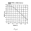
- This configuration yields a substantially linear relationship between operating torque and the axial distance or spacing between the concentric rings. This relationship is very stable over time and covers a wide range of operating torques, approximately between 5 in ⁇ lbs and 35 in ⁇ lbs.
- the invention provides a tool-less adjustment of the magnetic clutch.
- a torque-adjusting collar is rotatably adjustable around the spindle to initiate axial displacement of the inner magnet ring with respect to the fixed outer magnet ring, effectively eliminating the use of spacers to achieve a desired torque setting at the capping head.
- a detent mechanism is used to selectively lock and unlock the torque-adjusting collar, eliminating the need for any tooling or extended downtime to adjust the torque setting on the magnetic clutch to satisfy different closure specifications.
- the invention also provides a tool-less adjustment of the top-loading force applied by the spring to the closure.
- a combination of a spring retainer and an adjustment collar work to pre-load the spring between the upper housing and lower housing.
- the spring retainer is free to slide on the upper housing, while the adjustment collar is located above the retainer and is rotatably positioned using threads engaged with the upper housing.
- a clockwise rotation of the adjustment collar initiates a greater pre-load on the spring, and subsequently a greater top-loading force to the closure on the container.
- a counter-clockwise rotation yields the opposite results.
- One or more detent mechanisms are integrated between the adjustment collar and spring retainer to allow the collar to index between different amounts of pre-load on the spring. The detent mechanisms maintain and lock the collar in place during operation of the capping head.
- the invention provides a capping head without any conventional, resilient seals that require frequent replacement.
- a retainer positioned below the bearing includes an annular sidewall portion having a channel formed therein.
- the channel substantially prevents the liquid product from contaminating the bearing.
- the sidewall and channel of the metallic retainer do not wear over time.
- the magnetic clutch yields a more stable torque output for a longer period of time.
- the other components that experience wear during normal operation can be coated to prolong their useful life. The coatings are applied directly to the wear surfaces of the respective components and will not contaminate the liquid product.
- the invention also provides a method of adjusting the strength of the magnetic torque coupling on the capping head.
- the method includes rotating the torque adjusting collar relative to the spindle to impart an axial (and non-rotational) displacement of the inner ring of magnets relative to the outer ring of magnets between varying positions where the inner ring of magnets is nested within the outer ring of magnets, whereby varying the nested position of the two rings varies the strength of the torque coupling.
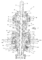
- FIG. 1 is a cross-sectional view of a screw capping head embodying the present invention.
- FIG. 2 is an exploded view showing the lower housing mating to the upper housing via male and female splines.
- FIG. 3 is a cross-sectional view of the torque carrier assembly of the screw capping head of FIG. 1.
- FIG. 4 illustrates the inner magnet assembly of the screw capping head of FIG. 1.
- FIG. 5 illustrates the outer magnet assembly of the screw capping head of FIG. 1.
- FIG. 6 is a Torque vs. Distance curve illustrating the relationship between torque applied by the capping head to a closure and the spaced distance between the inner and outer magnet assemblies.
- FIG. 7 illustrates the spindle, torque adjusting collar with detent mechanisms, and the carrier ring.
- FIG. 8 is a cross-section view along lines 8 - 8 of the carrier ring of FIG. 7.
- FIG. 1 A screw capping headset, or capping head 10 embodying the present invention is shown in FIG. 1.
- the capping head 10 is rotatably driven along a longitudinal axis 14 by a machine spindle (not shown) of a capping machine (not shown).
- the machine spindle is secured to the screw capping head 10 via a spindle adapter 18 .
- the spindle adapter 18 has internally formed threads 22 to secure the capping head 10 to the rotating spindle of the capping machine.
- a knock-out rod 26 travels vertically through the capping head 10 to expel any unneeded or jammed closures (not shown) from the capping head 10 .
- the knock-out rod 26 is biased towards an upper position by a compression spring 30 .
- a spring retainer 34 axially aligns the spring 30 with respect to the knock-out rod 26 and is positioned between the knock-out rod 26 and the spring 30 .
- the knock-out rod 26 is actuated by the capping machine. When actuated, the knock-out rod 26 travels to a lower position where the rod 26 contacts and expels the unneeded closure. The spring 30 and retainer 34 then force the rod to return to the upper position.
- a lower housing 38 and an upper housing 42 are keyed together by splined shafts.
- the lower housing 38 includes a male splined shaft 46 and the upper housing 42 includes a female splined shaft 50 , of course the lower housing 38 could include the female splined shaft 50 and the upper housing 42 could include the male splined shaft 46 .
- the shafts 46 , 50 engage each other and telescope coaxially along the longitudinal axis 14 .
- the upper housing 42 includes a circumferential ridge 54 concentric with the longitudinal axis 14 .
- the housings 38 , 42 are allowed to telescope a predetermined distance as a result of a knock-out rod housing 58 contacting the ridge 54 .
- the knock-out rod housing 58 secures the lower housing 38 to the upper housing 42 via eight cap screws 62 and prevents telescoping beyond the predetermined distance when the knock-out rod housing 58 comes into contact with the ridge 54 .
- a shock absorber 66 in the form of an polymeric disc is positioned between the knock-out rod housing 58 and the lower housing 38 to decrease wear between the metallic surfaces of the housings 58 , 38 .
- the upper housing 42 and portions of the lower housing 38 are coated to prolong their useful life and increase their corrosion resistance.
- the coatings can be applied by any conventional method such as spraying, dipping, or plating the components. In some instances, portions of a component will be coated rather than the entire component, and in other instances, the entire component will be coated for ease of application.
- the coated surfaces are indicated by the stippling seen in FIGS. 2, 4, 7 - 8 .
- the coating comprises a chrome-based coating having a thickness between about 0.0001 and 0.0003 inches and a hardness of about 78 Rc, however, different coatings having similar wear protection and corrosion resistance characteristics can also be used.
- the illustrated coating is marketed under the name ARMALOY and is available from Armaloy of Illinois, Inc. in DeKalb, Ill.
- cleaning the capping heads 10 is highly simplified because the entire capping head 10 can be sprayed down using a high pressure water stream. Previously, the lubricated surfaces would have to be avoided during cleaning because the water stream could dissipate the lubrication from the lubricated surfaces.
- a compression spring 70 is confined between a spring retainer 74 and the lower housing 38 .
- the spring 70 biases the housings 38 , 42 away from each other such that a force needs to be overcome for the housings 38 , 42 to telescope toward each other.
- a top load adjusting nut 78 threadably engages the upper housing 42 and is positioned above the spring retainer 74 .
- the nut 78 axially supports the retainer 74 against the force of the compression spring 70 .
- Rotation of the nut 78 results in its axial movement along the longitudinal axis 14 .
- the nut 78 can be rotatably adjusted to displace the retainer 74 and compress the spring 70 . This action imparts a pre-load on the spring 70 . This ensures the closure will be vertically applied to an open container (not shown) by a minimum force determined by the pre-load.
- the pre-load can be adjusted by rotating the nut 78 to increase or decrease the pre-load as required by closure application specifications.
- the retainer 74 includes an anti-rotation pin 82 that prevents the spring 70 from rotating relative to the housings 38 , 42 during operation.
- the retainer 74 is also coated similar to the upper housing 42 and lower housing 38 .
- the nut 78 includes four ball detent mechanisms 86 that engage four correlating recesses 90 in the retainer 74 and secure the nut 78 to prevent any unwanted rotation during operation of the capping head 10 .
- the nut 78 can utilize other locking mechanisms, such as one or more setscrews (not shown) to secure the nut 78 .
- the lower housing 38 contains the components involved with the magnetic torque coupling of the capping head 10 .
- the components generally include an outer magnet assembly 94 , a spindle assembly 98 , and a torque carrier assembly 102 .
- the outer magnet assembly 94 includes an outer carrier housing 106 having exterior threads 110 for threaded engagement with the lower housing 38 .
- the outer carrier housing 106 includes an outer ring 114 that is shrink fit into the interior of the housing 106 .
- the outer ring 114 is layered with a single row of outer magnets 118 positioned in a circular array. In the illustrated embodiment, the inside diameter of the outer ring 114 with the attached magnets 118 is about 2.125 inches.
- the magnets 118 are preferably made of a Sumarium Cobalt or similar magnetic material, with each magnet 118 having poles of opposite charge (e.g. a north and south pole).
- the magnets 118 are positioned on the outer ring 114 with either a north or south pole exposed to the interior of the outer magnet assembly 94 such that each magnet 118 has an adjacent magnet 118 with an opposite pole exposed.
- the magnets 118 are vacuum sealed and secured to the outer ring 114 by epoxy.
- the spindle assembly 98 includes a ball bearing 122 having an outer race 126 axially disposed between the outer carrier housing 106 and the lower housing 38 .
- the outer race 126 is rotatably fixed with respect to the lower housing 38 .
- the inner race 130 is free to rotate independently of the lower housing 38 and is axially disposed between an upper bearing retainer 134 and a lower bearing retainer 138 .
- a capping head spindle 142 (hereinafter referred to as the “spindle”) is secured to the upper bearing retainer 134 and lower bearing retainer 138 through six cap screws 144 and is free to rotate about the longitudinal axis 14 .
- the spindle 142 (see FIGS.
- the spindle 142 includes both exterior threads 146 and interior threads 150 on the lower portion of the spindle 142 .
- the spindle 142 also includes male splines 154 on its exterior surface towards the upper portion of the spindle 142 .
- the spindle 142 is also coated with the ARMALOY coating like the upper housing 42 and lower housing 38 to enhance wear protection and corrosion resistance.
- the lower bearing retainer 138 includes an annular portion or sidewall 158 having a channel 162 formed therein.
- the channel 162 is positioned below the bearing 122 and communicates with the outer carrier housing 106 .
- the sidewall 158 is closely spaced to the inner surface of the outer carrier housing 106 with the channel 162 extending radially inwardly toward the longitudinal axis 14 .
- the channel 162 substantially prevents the liquid product from contaminating the bearing 122 by providing a collection area for any liquid product coming in contact with the sidewall 158 .
- the sidewall 158 of the lower bearing retainer 138 is not in frictional contact with another surface and subsequently does not wear over time.
- the bearing 122 is lubricated using a food-grade type grease that substantially adheres to the lubricated surfaces of the bearing 122 .
- the channel 162 typically is not needed to prevent unwanted movement of bearing grease away from the bearing 122 and toward the liquid product.
- the torque carrier assembly 102 is positioned partially within the lower housing 38 and telescopes axially with respect to the spindle 142 along the longitudinal axis 14 .
- the torque carrier assembly 102 includes an inner magnet assembly 166 , a carrier ring 170 , a carrier coupling 174 , and a torque-adjusting collar 178 .
- the torque carrier assembly 102 is shown in greater detail in FIG. 3.
- the inner magnet assembly 166 (see FIG. 4) includes an inner magnet carrier 182 having female splines 186 on the interior of the carrier 182 .
- the female splines 186 engage the male splines 154 of the spindle 142 to allow the inner magnet assembly 166 , and subsequently the torque carrier assembly 102 , to telescope axially with respect to the spindle 142 .
- the splined engagement between the inner magnet assembly 166 and the spindle 142 also prevents rotation of the inner magnet assembly 166 relative to the spindle 142 .
- the inner magnet carrier 182 could have male splines 154 that engage female splines 186 of the spindle 142 .
- the female splines 186 of the inner magnet carrier 182 and the male splines 154 of the spindle 142 are also coated with the same coating applied to the upper housing 42 and lower housing 38 .
- conventional resilient seals are not required in the torque carrier assembly 102 because conventional lubricants are not needed.
- the inner magnet carrier 182 includes an inner ring 190 that is shrink fit over the inner magnet carrier 182 .
- the inner ring 190 is layered with a single row of inner magnets 194 positioned in a circular array.
- the magnets 194 are also preferably made of a Sumarium Cobalt or similar magnetic material, with each magnet 194 having poles of opposite charge (e.g. a north and south pole).
- the magnets 194 are also positioned on the inner ring 190 with either a north or south pole exposed to the exterior of the inner magnet assembly 166 such that each magnet 194 has an adjacent magnet 194 with an opposite pole exposed.
- the magnets 194 are vacuum sealed and secured to the inner ring 190 by epoxy.
- a sleeve 198 is shrink fit over the circular array of magnets 194 to lend additional radial support to the magnets 194 .
- the outer diameter of the inner ring 190 with the attached magnets 194 and sleeve 198 is about 2.1 inches. As a result, about 0.0125 inches of clearance exists between the inner magnet assembly 166 and outer magnet assembly 94 . This clearance allows the inner and outer magnet assemblies 166 , 94 to achieve a variety of coaxially nested positions with respect to one another.
- the inner magnet carrier 182 also includes exterior threads 202 on the lower portion of the carrier 182 .
- the carrier ring 170 includes interior threads 206 for threaded engagement with the exterior threads 202 of the inner magnet carrier 182 .
- the carrier ring 170 also includes a plurality of indexed recesses 210 or detents (see FIGS. 3 and 7) radially positioned around the bottom surface of the carrier ring 170 for receiving spring-loaded balls described below.
- the carrier ring 170 is coated similarly to the inner magnet carrier 182 to enhance wear protection and corrosion resistance.
- the carrier coupling 174 includes interior threads 214 for threaded engagement with the spindle 142 .
- the carrier coupling 174 also includes exterior threads 218 .
- One or more bushings 222 are positioned between the contacting surfaces of the inner magnet carrier 182 and the carrier coupling 174 to minimize wear between the carrier 182 and the coupling 174 .
- the torque-adjusting collar 178 includes interior threads 226 for threaded engagement with the exterior threads 218 of the carrier coupling 174 .
- the torque-adjusting collar 178 is also coated similarly to the inner magnet carrier 182 to enhance wear protection and corrosion resistance.
- the collar 178 also includes four ball detent mechanisms 230 radially positioned on the top surface of the collar 178 .
- the ball detent mechanisms 230 are equiangularly spaced to coincide with the indexed recesses 210 of the carrier ring 170 .
- the collar 178 also includes one locking ball detent mechanism 234 having a ball 235 actuated by a spring-biased push button 236 .
- the locking ball detent mechanism 234 rotatably locks the torque-adjusting collar 178 to the carrier ring 170 , which is coupled to the spindle 142 for rotation therewith.
- the push button 236 is depressed, the ball 235 disengages the carrier ring 170 and the collar 178 is allowed to co-rotate with the carrier coupling 174 about the exterior threads 146 of the spindle 142 . This action results in an axial displacement of the inner magnet assembly 166 with respect to the outer magnet assembly 94 .
- Utilizing the locking ball detent mechanism 234 in conjunction with the rotatably adjustable collar 178 allows the torque coupling between the magnet assemblies 94 , 166 to be changed by hand without using tools.
- the combination of the ball detent mechanisms 230 in the torque-adjusting collar 178 and the indexed recesses 210 in the carrier ring 170 allows the collar 178 to selectively index the axial position of the inner magnets 194 with respect to the outer magnets 118 .
- This configuration allows the capping head 10 to take advantage of the substantially linear relationship between the torque coupling of the nested magnets 118 , 194 and the vertical distance between the nested magnets 118 , 194 . This substantially linear relationship is shown in FIG. 6. Using this configuration, the capping head 10 can be adjusted to transmit between 5 in ⁇ lbs and 35 in ⁇ lbs of torque to a closure.
- a clockwise rotation (looking from the bottom of the capping head 10 ) of the torque-adjusting collar 178 causes the inner magnets 194 to displace axially away from (upwardly in FIG. 1) the outer magnets 118 .
- the inner magnets 194 yield the weakest torque coupling with the outer magnets 118
- a home position yields the strongest torque coupling between the magnets 118 , 194 .
- the home position is defined when the inner magnets 194 are completely nested within the outer magnets 118 , while the fully displaced position is defined by about 0.5 inches of vertical upward movement of the inner magnets 194 , where the bottom surfaces 238 of the inner magnets 194 are coplanar with the top surfaces 242 of the outer magnets 118 .
- the position of the inner magnets 194 relative to the outer magnets 118 is generally identified by reference numerals 246 engraved on the exterior of the collar 178 , as shown in FIG. 7.
- the numerals 246 are indexed and referenced to a calibration mark (not shown) on the carrier ring 170 . This allows a user to visually determine the torque setting of the capping head 10 .
- a lower numeral referenced to the calibration mark indicates a weaker torque coupling while a higher numeral referenced to the mark indicates a stronger torque coupling.
- the reference numerals 246 correlate to the actual amount of torque applied by the capping head 10 to a closure, such that the numeral “29” referenced to the calibration mark indicates that a torque of 29 in ⁇ lbs is applied to a closure. With this configuration, a torque wrench is not required to verify torque settings on individual capping heads 10 during a product changeover.
- the capping head 10 also includes a chuck assembly 250 rotatably supported within the spindle 142 . Exterior threads 254 on the chuck assembly 250 engage the interior threads 150 of the spindle 142 to secure the chuck assembly 250 to the spindle 142 for rotation therewith. A closure is secured within the chuck assembly 250 for application to an open container.
- the capping head 10 is pre-set to apply an amount of torque required by a production run of a particular open container. This is done by indexing the torque-adjusting collar 178 to the level of torque coupling desired. Upon application of the closure, the chuck assembly 250 will slip with the spindle 142 when the pre-set amount of torque is applied to the closure. This occurs because the torque coupling between the inner magnets 194 and outer magnets 118 is overcome.
- the spindle 142 When the spindle 142 slips, the spindle 142 ratchets due to alternating attraction and repulsion between the outer magnets 118 and inner magnets 194 .
- the outer magnets 118 with exposed “north” poles will attract the inner magnets 194 with exposed “south” poles to define a stable position between the outer magnets 118 and inner magnets 194 .
- the outer magnets 11 8 with exposed “north” poles will repulse the inner magnets 194 with exposed “north” poles to define an unstable position between the outer magnets 118 and inner magnets 194 .
- the magnets 118 , 194 alternating between stable and unstable positions cause the spindle 142 to ratchet when the spindle 142 slips.
- This ratcheting effect is advantageous for some closure applications and provides benefits over other prior art magnetic clutches that operate using the hysteresis phenomenon to provide smooth clutch action.
- FIGS. A-B illustrate a prior art capping head 1 including concentric and nested magnetic rings 3 , 5 that provide a magnetic torque coupling between a housing 7 and a spindle 9 .
- An outer metal ring 3 is rotatably fixed to the housing 7
- an inner ring 5 including magnets having alternating “north” and “south” poles exposed to the outer metal ring 3 is rotatably fixed to an adjustment collar 1 1 .
- the adjustment collar 11 includes interior threads 13 that engage exterior threads 15 of the spindle 9 , thereby allowing threaded rotational adjustment of the collar I 1 relative to the spindle 9 , which results in longitudinal and rotational movement of the inner ring 5 relative to the outer ring 3 .
- the capping head 1 utilizes the hysteresis phenomenon to provide the torque coupling between the outer metal ring 3 and the inner ring 5 .
- FIGS. C-D illustrate the spindle 9 and adjustment collar 11 respectively, showing the location of the exterior threads 15 and interior threads 13 that allow the adjustment collar 11 to rotate relative to the spindle 9 .
- Setscrews (not shown) are threaded into the adjustment collar 11 such that rotation of the collar 11 relative to the spindle 9 is substantially prevented when the setscrews frictionally contact against the spindle 9 .
- the setscrews are first loosened from the spindle 9 .
- the user secures the spindle 9 with one hand while turning the adjustment collar 11 with the other hand to the desired torque coupling.
- the setscrews are then re-tightened against the spindle 9 to substantially prevent rotation of the collar 11 relative to the spindle 9 during operation.
Landscapes
- Engineering & Computer Science (AREA)
- Mechanical Engineering (AREA)
- Physics & Mathematics (AREA)
- Electromagnetism (AREA)
- Sealing Of Jars (AREA)
Abstract
Description
- This invention relates generally to rotary capping machines, and more particularly to rotary capping machines that apply pre-threaded closures onto pre-threaded containers.
- Rotary capping machines for applying pre-threaded closures have been known for some time. To insure that a pre-threaded closure is not applied too loosely or too tightly and to insure product integrity, rotary capping machines are equipped with capping heads dependent upon a torque coupling. The torque coupling controls the application of torque to the closures to insure that they meet packaging specifications. Various types of torque couplings exist in the art such as mechanical clutches and magnetic clutches.
- A magnetic clutch typically consists of axially-opposed rings that are spaced apart by some distance. Each ring comprises an array of magnets mounted horizontally along each ring whereby the arrays of magnets on the opposing rings are in a facing relationship. In a magnetic clutch, one ring is typically fixed within a housing that is driven by a machine spindle and the other ring drives a capping head spindle that holds the closures. The magnetic field established between the arrays of magnets is the connection between the torque applied to the housing by the machine spindle and the torque applied to the closure by the capping head spindle. Axial distance between the opposing rings affects the torque transmitted by the magnetic clutch. Generally, a greater distance between the rings will decrease the magnetic interaction between the opposing arrays of magnets, and subsequently will decrease the amount of transmittable torque carried by the magnetic clutch. Any resistance torque applied to the magnetic clutch by the spindle beyond that of the transmittable torque causes the clutch to slip. Generally, spacer rings are used to maintain the distance between the opposing magnetic rings.
- In addition to the clutch, each capping head also typically utilizes a telescoping lower/upper housing design, with the clutch located in the lower housing near the spindle. A spring is usually positioned between the upper housing and lower housing to help bias the housings away from each other and to exert a top-loading force on the closure to the container. The pre-load on the spring can be adjusted to vary the top-loading force on the closure, and this is often accomplished using a rotatable collar with a locking element, such as a set screw, that must be loosened to adjust the collar and tightened after the adjustment is made. Alternatively, the spring can be removed and replaced with another spring of a different stiffness.
- A typical capping head utilizing a magnetic clutch requires the use of tools for torque adjustment. To adjust the torque transmitted by the magnetic clutch, spacer rings must either be inserted or removed, depending on the design of the capping head. This often requires each capping head to be disassembled or adjusted using tools, and this extends the downtime associated with setting up a capping machine to run a specific package. After the capping head is adjusted, a torque wrench is required to verify the torque setting on the capping head. This is necessary to ensure all the capping heads on a rotary capping machine apply substantially the same amount of torque to closures on open containers.
- Downtime is also extended when the top-loading force on the closure needs adjusting. Each capping head must be disassembled or adjusted using tools if the springs are to be replaced with springs of a different stiffness. If a capping head utilizes a collar with a locking element to adjust the top-loading force on the closure, then tooling is often required to carry out the adjustment. In either case, downtime is lengthened.
- The typical capping head also requires seals such as O-rings and quad rings to prevent the environment and/or the product from entering and attacking the internal components of the capping head. The seals also prevent any lubrication in the capping head from escaping and contaminating the product being packaged. Failure of the seals often leads to a complete failure of the capping head. An erratic torque output also often results from worn or failed seals. To help prevent this from occurring, the capping heads require frequent maintenance to inspect and replace any worn seals and bearings.
- The relatively large inertial mass of the capping head plus the friction of the seals often produce erratic torque output through the magnetic clutch. This is most common in high speed capping applications. To help address this problem, some capping machines have been provided with different sets of capping heads for different operating speed ranges. This approach has been helpful, but it has also been uneconomical and has unduly complicated and lengthened the changeover between packaging runs requiring two very different operating speeds. Prior attempts to reduce capping head inertia have been negligible at improving erratic torque output.
- The magnetic clutch configuration utilizing two opposing magnetic rings that are in a facing relationship typically has a non-linear relationship between operating torque and the distance between the opposing magnets. This relationship is known in the art and has proven to be relatively unstable over time. As a result, each capping head may require frequent re-calibration to maintain accurate and repeatable closure applications on the containers. This practice also lengthens downtime and is uneconomical.
- The invention provides for significant improvement for a screw capping head having a magnetic clutch for transmission of torque to a closure. The invention provides a capping head utilizing a single bearing and no conventional, resilient seals, therefore eliminating frictional resistance, extending maintenance intervals, reducing production downtime, and lowering the cost of operation.
- More specifically, the invention provides in one embodiment a capping head having a torque coupling consisting of a magnetic clutch that yields a predictable torque output, thereby allowing for indexed torque adjustment and eliminating the need for frequent re-calibration of the capping heads. The magnetic clutch comprises two concentric rings with rectangular magnets affixed vertically along the rings. The rectangular magnets are preferably vacuum sealed in epoxy to provide corrosion protection from the environment. An outer ring is affixed to a lower housing while an inner ring is coupled around a spindle and positioned at least partially within the outer ring. The inner ring moves axially (and not rotationally) into and out of nested relationship with respect to the outer ring, which is fixed to the lower housing. This configuration yields a substantially linear relationship between operating torque and the axial distance or spacing between the concentric rings. This relationship is very stable over time and covers a wide range of operating torques, approximately between 5 in·lbs and 35 in·lbs.
- In another embodiment, the invention provides a tool-less adjustment of the magnetic clutch. A torque-adjusting collar is rotatably adjustable around the spindle to initiate axial displacement of the inner magnet ring with respect to the fixed outer magnet ring, effectively eliminating the use of spacers to achieve a desired torque setting at the capping head. A detent mechanism is used to selectively lock and unlock the torque-adjusting collar, eliminating the need for any tooling or extended downtime to adjust the torque setting on the magnetic clutch to satisfy different closure specifications.
- In another embodiment, the invention also provides a tool-less adjustment of the top-loading force applied by the spring to the closure. A combination of a spring retainer and an adjustment collar work to pre-load the spring between the upper housing and lower housing. The spring retainer is free to slide on the upper housing, while the adjustment collar is located above the retainer and is rotatably positioned using threads engaged with the upper housing. A clockwise rotation of the adjustment collar initiates a greater pre-load on the spring, and subsequently a greater top-loading force to the closure on the container. A counter-clockwise rotation yields the opposite results. One or more detent mechanisms are integrated between the adjustment collar and spring retainer to allow the collar to index between different amounts of pre-load on the spring. The detent mechanisms maintain and lock the collar in place during operation of the capping head.
- In yet another embodiment, the invention provides a capping head without any conventional, resilient seals that require frequent replacement. Rather, a retainer positioned below the bearing includes an annular sidewall portion having a channel formed therein. The channel substantially prevents the liquid product from contaminating the bearing. Unlike a conventional resilient seal, however, the sidewall and channel of the metallic retainer do not wear over time. As a result, the magnetic clutch yields a more stable torque output for a longer period of time. To forego the use of conventional lubricants and resilient seals, while maintaining the bearing as the only conventionally lubricated component within the capping head, the other components that experience wear during normal operation can be coated to prolong their useful life. The coatings are applied directly to the wear surfaces of the respective components and will not contaminate the liquid product.
- The invention also provides a method of adjusting the strength of the magnetic torque coupling on the capping head. The method includes rotating the torque adjusting collar relative to the spindle to impart an axial (and non-rotational) displacement of the inner ring of magnets relative to the outer ring of magnets between varying positions where the inner ring of magnets is nested within the outer ring of magnets, whereby varying the nested position of the two rings varies the strength of the torque coupling.
- Other features and advantages of the invention will become apparent to those skilled in the art upon review of the following detailed description and drawings.
- FIG. 1 is a cross-sectional view of a screw capping head embodying the present invention.
- FIG. 2 is an exploded view showing the lower housing mating to the upper housing via male and female splines.
- FIG. 3 is a cross-sectional view of the torque carrier assembly of the screw capping head of FIG. 1.
- FIG. 4 illustrates the inner magnet assembly of the screw capping head of FIG. 1.
- FIG. 5 illustrates the outer magnet assembly of the screw capping head of FIG. 1.
- FIG. 6 is a Torque vs. Distance curve illustrating the relationship between torque applied by the capping head to a closure and the spaced distance between the inner and outer magnet assemblies.
- FIG. 7 illustrates the spindle, torque adjusting collar with detent mechanisms, and the carrier ring.
- FIG. 8 is a cross-section view along lines 8-8 of the carrier ring of FIG. 7.
- Before one embodiment of the invention is explained in detail, it is to be understood that the invention is not limited in its application to the details of construction and the arrangements of the components set forth in the following description or illustrated in the drawings. The invention is capable of other embodiments and of being practiced or being carried out in various ways. Also, it is understood that the phraseology and terminology used herein is for the purpose of description and should not be regarded as limiting. The use of “including” and “comprising” and variations thereof herein is meant to encompass the items listed thereafter and equivalents thereof as well as additional items.
- A screw capping headset, or capping
head 10 embodying the present invention is shown in FIG. 1. The cappinghead 10 is rotatably driven along alongitudinal axis 14 by a machine spindle (not shown) of a capping machine (not shown). The machine spindle is secured to thescrew capping head 10 via aspindle adapter 18. Thespindle adapter 18 has internally formedthreads 22 to secure the cappinghead 10 to the rotating spindle of the capping machine. - A knock-out
rod 26 travels vertically through the cappinghead 10 to expel any unneeded or jammed closures (not shown) from the cappinghead 10. The knock-outrod 26 is biased towards an upper position by acompression spring 30. Aspring retainer 34 axially aligns thespring 30 with respect to the knock-outrod 26 and is positioned between the knock-outrod 26 and thespring 30. - During operation, the knock-out
rod 26 is actuated by the capping machine. When actuated, the knock-outrod 26 travels to a lower position where therod 26 contacts and expels the unneeded closure. Thespring 30 andretainer 34 then force the rod to return to the upper position. - As best seen in FIG. 2, a
lower housing 38 and anupper housing 42 are keyed together by splined shafts. Thelower housing 38 includes a malesplined shaft 46 and theupper housing 42 includes a femalesplined shaft 50, of course thelower housing 38 could include the femalesplined shaft 50 and theupper housing 42 could include the malesplined shaft 46. Theshafts longitudinal axis 14. With reference to FIG. 1, theupper housing 42 includes acircumferential ridge 54 concentric with thelongitudinal axis 14. Thehousings rod housing 58 contacting theridge 54. The knock-outrod housing 58 secures thelower housing 38 to theupper housing 42 via eightcap screws 62 and prevents telescoping beyond the predetermined distance when the knock-outrod housing 58 comes into contact with theridge 54. Ashock absorber 66 in the form of an polymeric disc is positioned between the knock-outrod housing 58 and thelower housing 38 to decrease wear between the metallic surfaces of thehousings - The
upper housing 42 and portions of thelower housing 38 are coated to prolong their useful life and increase their corrosion resistance. The coatings can be applied by any conventional method such as spraying, dipping, or plating the components. In some instances, portions of a component will be coated rather than the entire component, and in other instances, the entire component will be coated for ease of application. The coated surfaces are indicated by the stippling seen in FIGS. 2, 4, 7-8. - The coating comprises a chrome-based coating having a thickness between about 0.0001 and 0.0003 inches and a hardness of about 78 Rc, however, different coatings having similar wear protection and corrosion resistance characteristics can also be used. The illustrated coating is marketed under the name ARMALOY and is available from Armaloy of Illinois, Inc. in DeKalb, Ill. By applying coatings to the wear surfaces of the capping
head 10, such as the male and femalesplined shafts splined shafts upper housing 42 orlower housing 38. Also, cleaning the capping heads 10 is highly simplified because theentire capping head 10 can be sprayed down using a high pressure water stream. Previously, the lubricated surfaces would have to be avoided during cleaning because the water stream could dissipate the lubrication from the lubricated surfaces. - A
compression spring 70 is confined between aspring retainer 74 and thelower housing 38. Thespring 70 biases thehousings housings load adjusting nut 78 threadably engages theupper housing 42 and is positioned above thespring retainer 74. Thenut 78 axially supports theretainer 74 against the force of thecompression spring 70. Rotation of thenut 78 results in its axial movement along thelongitudinal axis 14. Thenut 78 can be rotatably adjusted to displace theretainer 74 and compress thespring 70. This action imparts a pre-load on thespring 70. This ensures the closure will be vertically applied to an open container (not shown) by a minimum force determined by the pre-load. - The pre-load can be adjusted by rotating the
nut 78 to increase or decrease the pre-load as required by closure application specifications. Theretainer 74 includes ananti-rotation pin 82 that prevents thespring 70 from rotating relative to thehousings retainer 74 is also coated similar to theupper housing 42 andlower housing 38. Thenut 78 includes fourball detent mechanisms 86 that engage four correlatingrecesses 90 in theretainer 74 and secure thenut 78 to prevent any unwanted rotation during operation of the cappinghead 10. Alternatively, thenut 78 can utilize other locking mechanisms, such as one or more setscrews (not shown) to secure thenut 78. - The
lower housing 38 contains the components involved with the magnetic torque coupling of the cappinghead 10. The components generally include anouter magnet assembly 94, aspindle assembly 98, and atorque carrier assembly 102. - As shown in FIGS. 1 and 5, the
outer magnet assembly 94 includes anouter carrier housing 106 havingexterior threads 110 for threaded engagement with thelower housing 38. Theouter carrier housing 106 includes anouter ring 114 that is shrink fit into the interior of thehousing 106. Theouter ring 114 is layered with a single row ofouter magnets 118 positioned in a circular array. In the illustrated embodiment, the inside diameter of theouter ring 114 with the attachedmagnets 118 is about 2.125 inches. Themagnets 118 are preferably made of a Sumarium Cobalt or similar magnetic material, with eachmagnet 118 having poles of opposite charge (e.g. a north and south pole). Themagnets 118 are positioned on theouter ring 114 with either a north or south pole exposed to the interior of theouter magnet assembly 94 such that eachmagnet 118 has anadjacent magnet 118 with an opposite pole exposed. Themagnets 118 are vacuum sealed and secured to theouter ring 114 by epoxy. - As best seen in FIG. 1, the
spindle assembly 98 includes aball bearing 122 having anouter race 126 axially disposed between theouter carrier housing 106 and thelower housing 38. As a result, theouter race 126 is rotatably fixed with respect to thelower housing 38. Theinner race 130, however, is free to rotate independently of thelower housing 38 and is axially disposed between anupper bearing retainer 134 and alower bearing retainer 138. A capping head spindle 142 (hereinafter referred to as the “spindle”) is secured to theupper bearing retainer 134 andlower bearing retainer 138 through sixcap screws 144 and is free to rotate about thelongitudinal axis 14. The spindle 142 (see FIGS. 1 and 7) includes bothexterior threads 146 andinterior threads 150 on the lower portion of thespindle 142. Thespindle 142 also includesmale splines 154 on its exterior surface towards the upper portion of thespindle 142. Thespindle 142 is also coated with the ARMALOY coating like theupper housing 42 andlower housing 38 to enhance wear protection and corrosion resistance. - The
lower bearing retainer 138 includes an annular portion orsidewall 158 having achannel 162 formed therein. Thechannel 162 is positioned below thebearing 122 and communicates with theouter carrier housing 106. Thesidewall 158 is closely spaced to the inner surface of theouter carrier housing 106 with thechannel 162 extending radially inwardly toward thelongitudinal axis 14. Thechannel 162 substantially prevents the liquid product from contaminating thebearing 122 by providing a collection area for any liquid product coming in contact with thesidewall 158. Unlike a conventional resilient seal that is typically in sliding frictional contact with another mating surface, thesidewall 158 of thelower bearing retainer 138 is not in frictional contact with another surface and subsequently does not wear over time. - The
bearing 122 is lubricated using a food-grade type grease that substantially adheres to the lubricated surfaces of thebearing 122. As a result, thechannel 162 typically is not needed to prevent unwanted movement of bearing grease away from thebearing 122 and toward the liquid product. - The
torque carrier assembly 102 is positioned partially within thelower housing 38 and telescopes axially with respect to thespindle 142 along thelongitudinal axis 14. Thetorque carrier assembly 102 includes aninner magnet assembly 166, acarrier ring 170, acarrier coupling 174, and a torque-adjustingcollar 178. Thetorque carrier assembly 102 is shown in greater detail in FIG. 3. - The inner magnet assembly 166 (see FIG. 4) includes an
inner magnet carrier 182 havingfemale splines 186 on the interior of thecarrier 182. Thefemale splines 186 engage themale splines 154 of thespindle 142 to allow theinner magnet assembly 166, and subsequently thetorque carrier assembly 102, to telescope axially with respect to thespindle 142. The splined engagement between theinner magnet assembly 166 and thespindle 142 also prevents rotation of theinner magnet assembly 166 relative to thespindle 142. Of course, theinner magnet carrier 182 could havemale splines 154 that engagefemale splines 186 of thespindle 142. - The
female splines 186 of theinner magnet carrier 182 and themale splines 154 of thespindle 142 are also coated with the same coating applied to theupper housing 42 andlower housing 38. As a result, conventional resilient seals are not required in thetorque carrier assembly 102 because conventional lubricants are not needed. Theinner magnet carrier 182 includes aninner ring 190 that is shrink fit over theinner magnet carrier 182. - The
inner ring 190 is layered with a single row ofinner magnets 194 positioned in a circular array. Themagnets 194 are also preferably made of a Sumarium Cobalt or similar magnetic material, with eachmagnet 194 having poles of opposite charge (e.g. a north and south pole). Themagnets 194 are also positioned on theinner ring 190 with either a north or south pole exposed to the exterior of theinner magnet assembly 166 such that eachmagnet 194 has anadjacent magnet 194 with an opposite pole exposed. Themagnets 194 are vacuum sealed and secured to theinner ring 190 by epoxy. Asleeve 198 is shrink fit over the circular array ofmagnets 194 to lend additional radial support to themagnets 194. In the illustrated embodiment, the outer diameter of theinner ring 190 with the attachedmagnets 194 andsleeve 198 is about 2.1 inches. As a result, about 0.0125 inches of clearance exists between theinner magnet assembly 166 andouter magnet assembly 94. This clearance allows the inner andouter magnet assemblies inner magnet carrier 182 also includesexterior threads 202 on the lower portion of thecarrier 182. - Referring again to FIGS. 1 and 3, the
carrier ring 170 includesinterior threads 206 for threaded engagement with theexterior threads 202 of theinner magnet carrier 182. Thecarrier ring 170 also includes a plurality of indexedrecesses 210 or detents (see FIGS. 3 and 7) radially positioned around the bottom surface of thecarrier ring 170 for receiving spring-loaded balls described below. As shown in FIGS. 7 and 8, thecarrier ring 170 is coated similarly to theinner magnet carrier 182 to enhance wear protection and corrosion resistance. - The
carrier coupling 174 includesinterior threads 214 for threaded engagement with thespindle 142. Thecarrier coupling 174 also includesexterior threads 218. One ormore bushings 222 are positioned between the contacting surfaces of theinner magnet carrier 182 and thecarrier coupling 174 to minimize wear between thecarrier 182 and thecoupling 174. - As shown in FIGS. 1 and 7, the torque-adjusting
collar 178 includesinterior threads 226 for threaded engagement with theexterior threads 218 of thecarrier coupling 174. The torque-adjustingcollar 178 is also coated similarly to theinner magnet carrier 182 to enhance wear protection and corrosion resistance. Thecollar 178 also includes fourball detent mechanisms 230 radially positioned on the top surface of thecollar 178. Theball detent mechanisms 230 are equiangularly spaced to coincide with theindexed recesses 210 of thecarrier ring 170. - The
collar 178 also includes one lockingball detent mechanism 234 having aball 235 actuated by a spring-biasedpush button 236. The lockingball detent mechanism 234 rotatably locks the torque-adjustingcollar 178 to thecarrier ring 170, which is coupled to thespindle 142 for rotation therewith. When thepush button 236 is depressed, theball 235 disengages thecarrier ring 170 and thecollar 178 is allowed to co-rotate with thecarrier coupling 174 about theexterior threads 146 of thespindle 142. This action results in an axial displacement of theinner magnet assembly 166 with respect to theouter magnet assembly 94. Utilizing the lockingball detent mechanism 234 in conjunction with the rotatablyadjustable collar 178 allows the torque coupling between themagnet assemblies - The combination of the
ball detent mechanisms 230 in the torque-adjustingcollar 178 and theindexed recesses 210 in thecarrier ring 170 allows thecollar 178 to selectively index the axial position of theinner magnets 194 with respect to theouter magnets 118. This configuration allows the cappinghead 10 to take advantage of the substantially linear relationship between the torque coupling of the nestedmagnets magnets head 10 can be adjusted to transmit between 5 in·lbs and 35 in·lbs of torque to a closure. - In the illustrated embodiment shown in FIG. 1, a clockwise rotation (looking from the bottom of the capping head 10) of the torque-adjusting
collar 178 causes theinner magnets 194 to displace axially away from (upwardly in FIG. 1) theouter magnets 118. In a fully displaced position, theinner magnets 194 yield the weakest torque coupling with theouter magnets 118, while a home position yields the strongest torque coupling between themagnets inner magnets 194 are completely nested within theouter magnets 118, while the fully displaced position is defined by about 0.5 inches of vertical upward movement of theinner magnets 194, where the bottom surfaces 238 of theinner magnets 194 are coplanar with thetop surfaces 242 of theouter magnets 118. - The position of the
inner magnets 194 relative to theouter magnets 118 is generally identified byreference numerals 246 engraved on the exterior of thecollar 178, as shown in FIG. 7. Thenumerals 246 are indexed and referenced to a calibration mark (not shown) on thecarrier ring 170. This allows a user to visually determine the torque setting of the cappinghead 10. Generally, a lower numeral referenced to the calibration mark indicates a weaker torque coupling while a higher numeral referenced to the mark indicates a stronger torque coupling. Thereference numerals 246 correlate to the actual amount of torque applied by the cappinghead 10 to a closure, such that the numeral “29” referenced to the calibration mark indicates that a torque of 29 in·lbs is applied to a closure. With this configuration, a torque wrench is not required to verify torque settings on individual capping heads 10 during a product changeover. - As shown in FIG. 1, the capping
head 10 also includes achuck assembly 250 rotatably supported within thespindle 142.Exterior threads 254 on thechuck assembly 250 engage theinterior threads 150 of thespindle 142 to secure thechuck assembly 250 to thespindle 142 for rotation therewith. A closure is secured within thechuck assembly 250 for application to an open container. - During operation, the capping
head 10 is pre-set to apply an amount of torque required by a production run of a particular open container. This is done by indexing the torque-adjustingcollar 178 to the level of torque coupling desired. Upon application of the closure, thechuck assembly 250 will slip with thespindle 142 when the pre-set amount of torque is applied to the closure. This occurs because the torque coupling between theinner magnets 194 andouter magnets 118 is overcome. - When the
spindle 142 slips, thespindle 142 ratchets due to alternating attraction and repulsion between theouter magnets 118 andinner magnets 194. For example, theouter magnets 118 with exposed “north” poles will attract theinner magnets 194 with exposed “south” poles to define a stable position between theouter magnets 118 andinner magnets 194. Conversely, the outer magnets 11 8 with exposed “north” poles will repulse theinner magnets 194 with exposed “north” poles to define an unstable position between theouter magnets 118 andinner magnets 194. Themagnets spindle 142 to ratchet when thespindle 142 slips. This ratcheting effect is advantageous for some closure applications and provides benefits over other prior art magnetic clutches that operate using the hysteresis phenomenon to provide smooth clutch action. - The absence of conventional resilient seals enhances the performance and longevity of the capping
head 10. Generally, when conventional resilient seals wear, the relationship between torque coupling and axial distance between themagnets head 10 can utilize longer maintenance intervals between servicing or replacement. This also allows the cappinghead 10 to more accurately and precisely apply the closures with a pre-set amount of torque, which will subsequently decrease the number of rejected product containers due to improper application of closures to the open containers. - Various features of the invention are set forth in the following claims.
- FIGS. A-B illustrate a prior art capping head 1 including concentric and nested
magnetic rings 3, 5 that provide a magnetic torque coupling between a housing 7 and a spindle 9. An outer metal ring 3 is rotatably fixed to the housing 7, while aninner ring 5 including magnets having alternating “north” and “south” poles exposed to the outer metal ring 3 is rotatably fixed to an adjustment collar 1 1. The adjustment collar 11 includes interior threads 13 that engage exterior threads 15 of the spindle 9, thereby allowing threaded rotational adjustment of the collar I 1 relative to the spindle 9, which results in longitudinal and rotational movement of theinner ring 5 relative to the outer ring 3. The capping head 1 utilizes the hysteresis phenomenon to provide the torque coupling between the outer metal ring 3 and theinner ring 5. - FIGS. C-D illustrate the spindle 9 and adjustment collar 11 respectively, showing the location of the exterior threads 15 and interior threads 13 that allow the adjustment collar 11 to rotate relative to the spindle 9. Setscrews (not shown) are threaded into the adjustment collar 11 such that rotation of the collar 11 relative to the spindle 9 is substantially prevented when the setscrews frictionally contact against the spindle 9.
- To adjust the torque coupling between the outer metal ring 3 and the
inner ring 5, the setscrews are first loosened from the spindle 9. The user then secures the spindle 9 with one hand while turning the adjustment collar 11 with the other hand to the desired torque coupling. The setscrews are then re-tightened against the spindle 9 to substantially prevent rotation of the collar 11 relative to the spindle 9 during operation.
Claims (25)
Priority Applications (1)
| Application Number | Priority Date | Filing Date | Title |
|---|---|---|---|
| US10/164,252 US6941724B2 (en) | 2001-06-07 | 2002-06-06 | Screw capping head |
Applications Claiming Priority (2)
| Application Number | Priority Date | Filing Date | Title |
|---|---|---|---|
| US29656001P | 2001-06-07 | 2001-06-07 | |
| US10/164,252 US6941724B2 (en) | 2001-06-07 | 2002-06-06 | Screw capping head |
Publications (2)
| Publication Number | Publication Date |
|---|---|
| US20020184853A1 true US20020184853A1 (en) | 2002-12-12 |
| US6941724B2 US6941724B2 (en) | 2005-09-13 |
Family
ID=26860394
Family Applications (1)
| Application Number | Title | Priority Date | Filing Date |
|---|---|---|---|
| US10/164,252 Expired - Fee Related US6941724B2 (en) | 2001-06-07 | 2002-06-06 | Screw capping head |
Country Status (1)
| Country | Link |
|---|---|
| US (1) | US6941724B2 (en) |
Cited By (20)
| Publication number | Priority date | Publication date | Assignee | Title |
|---|---|---|---|---|
| US20060260277A1 (en) * | 2005-05-19 | 2006-11-23 | Serac Group | Device for screwing caps onto receptacles |
| EP1772421A1 (en) * | 2005-10-04 | 2007-04-11 | Adcor Industries, Inc. | Capping device with force adjustment mechanism |
| US20080127611A1 (en) * | 2005-10-04 | 2008-06-05 | Adcor Industries, Inc. | Capping device with bearing mechanism having a plurality of bearing members between a drive member and a capper body |
| US20090193759A1 (en) * | 2004-06-03 | 2009-08-06 | Toyo Seikan Kaisha, Ltd. | Capper head |
| US20100095636A1 (en) * | 2008-10-17 | 2010-04-22 | Sergio Cirio | Head for the application of threaded caps on containers |
| US20120011809A1 (en) * | 2010-07-13 | 2012-01-19 | Sergio Cirio | Head for applying threaded caps on containers |
| CN102923624A (en) * | 2012-10-25 | 2013-02-13 | 哈尔滨商业大学 | Automatic screwing device for single-port spherical screw plug |
| US20130255187A1 (en) * | 2012-04-03 | 2013-10-03 | Closure Systems International, Inc. | Height-adjustable capping chuck assembly |
| US20150175398A1 (en) * | 2012-08-07 | 2015-06-25 | Cedrex A/S | Test Tube Capping And De-Capping Apparatus |
| US9764864B1 (en) * | 2012-10-26 | 2017-09-19 | Change Parts, Inc. | Transgrip arm assembly with quick change connection |
| US20180155173A1 (en) * | 2016-12-06 | 2018-06-07 | Michael P. Scott | Capping chuck assembly |
| CN108975248A (en) * | 2018-09-18 | 2018-12-11 | 广州利沃包装机械有限公司 | A kind of perseverance torsion Cao rotating head assembly |
| CN109928346A (en) * | 2019-03-08 | 2019-06-25 | 荣成泰祥食品股份有限公司 | A kind of production method of canned fish sealing device and canned fish |
| EP3828128A1 (en) * | 2019-11-28 | 2021-06-02 | Krones Ag | Device for closing a container with a screw cap |
| US11174142B2 (en) * | 2018-10-31 | 2021-11-16 | Mbf S.P.A. | Motion transmission group for capping heads for screw caps and capping machine equipped with such a motion transmission group |
| US11192767B2 (en) * | 2016-10-21 | 2021-12-07 | Arol S.P.A. | Capping head for the application of caps on containers or bottles |
| CN115180576A (en) * | 2022-08-11 | 2022-10-14 | 湖南精正同业机械有限公司 | An aseptic capping head assembly with adjustable torque |
| US20240413701A1 (en) * | 2023-06-09 | 2024-12-12 | Schaeffler Technologies AG & Co. KG | Seal for linear actuator |
| CN119929239A (en) * | 2025-04-07 | 2025-05-06 | 常州海特赐仁传动科技有限公司 | An adjustable rotating ball spline based on self-locking |
| US20250289698A1 (en) * | 2024-03-18 | 2025-09-18 | Krones Ag | Closure head for closing containers |
Families Citing this family (9)
| Publication number | Priority date | Publication date | Assignee | Title |
|---|---|---|---|---|
| DE502006007120D1 (en) * | 2005-09-09 | 2010-07-15 | Alcoa Deutschland Gmbh | CLOSING DEVICE FOR APPLYING SCREW LOCKS TO TANKS |
| US20070261868A1 (en) * | 2006-05-12 | 2007-11-15 | Gross James R | Magnetic torque-limiting device and method |
| US7596932B2 (en) * | 2007-01-17 | 2009-10-06 | Parata Systems, Llc | Devices for capping vials useful in system and method for dispensing prescriptions |
| US20100012637A1 (en) * | 2008-07-16 | 2010-01-21 | Illinois Tool Works Inc. | Robotic gmaw torch with quick release gooseneck locking mechanism, dual alignment features, and multiple electrical contacts |
| DE102008061848A1 (en) * | 2008-12-15 | 2010-07-01 | Khs Ag | Apparatus and method for closing containers with a closure |
| US8282268B2 (en) * | 2009-02-24 | 2012-10-09 | Island Oasis Frozen Cocktail Co., Inc. | Magnetic drive for food processing apparatus |
| US8550388B2 (en) | 2010-03-15 | 2013-10-08 | Moog Inc. | Drive circuit with integrated power factor correction for blender/shaver machine |
| US8499649B2 (en) | 2010-05-19 | 2013-08-06 | Seagate Technology Llc | Testing a torque tool |
| PL2502875T3 (en) | 2011-03-24 | 2015-01-30 | Antonio Mengibar S A | Magnetic clutch |
Citations (47)
| Publication number | Priority date | Publication date | Assignee | Title |
|---|---|---|---|---|
| US3715865A (en) * | 1970-11-05 | 1973-02-13 | Sweetheart Plastics | Capping device for containers |
| US3757487A (en) * | 1971-12-30 | 1973-09-11 | American Bottlers Equip | Thread forming capping head |
| US3771283A (en) * | 1972-08-30 | 1973-11-13 | Pittsburh Aluminum | Capping head and machine |
| US3895478A (en) * | 1971-07-09 | 1975-07-22 | Continental Can Co | Roll on capping head |
| US3974884A (en) * | 1973-07-02 | 1976-08-17 | Atlas Copco Aktiebolag | Power wrench with magnetic sleeves for variable torque output |
| US4086747A (en) * | 1977-05-05 | 1978-05-02 | Aluminum Company Of America | Headset device for a capping machine |
| US4173104A (en) * | 1978-04-17 | 1979-11-06 | American Flange & Manufacturing Co., Inc. | Bottle capping apparatus and method |
| US4222215A (en) * | 1978-04-07 | 1980-09-16 | Kewpie Kabushiki Kaisha | Screw-capping device |
| US4276734A (en) * | 1979-04-16 | 1981-07-07 | Lykes Pasco Packing Company | Rotary filling and capping apparatus |
| US4295320A (en) * | 1980-01-09 | 1981-10-20 | Owens-Illinois, Inc. | Closure conversion apparatus for existing closure applicating machines |
| US4304611A (en) * | 1980-04-24 | 1981-12-08 | Aluminum Company Of America | Method and apparatus for cleaning container closures |
| US4437289A (en) * | 1980-11-07 | 1984-03-20 | Etablissements Larrieubedin "La Girondine" | Automatic machine for capping and labelling bottles or like containers |
| US4535583A (en) * | 1982-10-04 | 1985-08-20 | Shibuya Kogyo Co., Ltd. | Rotary type capping apparatus |
| US4557029A (en) * | 1983-03-15 | 1985-12-10 | Stewart Richard M | Core capping apparatus |
| US4562685A (en) * | 1984-02-02 | 1986-01-07 | Yoshiaki Tomita | Bottle capping apparatus |
| US4571920A (en) * | 1983-11-29 | 1986-02-25 | Apv Burnett & Rolfe, Inc. | Beer keg capping machine |
| US4599846A (en) * | 1984-04-19 | 1986-07-15 | Aluminum Company Of America | Capping head |
| US4604853A (en) * | 1984-12-03 | 1986-08-12 | Aluminum Company Of America | Method and apparatus for sealing a container with a tamper-evident closure |
| US4608806A (en) * | 1982-08-17 | 1986-09-02 | Metal Box Plc | Capping machines |
| US4633646A (en) * | 1985-10-29 | 1987-01-06 | Aluminum Company Of America | Capping head |
| US4658565A (en) * | 1986-03-13 | 1987-04-21 | Figgie International Inc. | Capping machine |
| US4674264A (en) * | 1986-02-03 | 1987-06-23 | Aluminum Company Of America | Screwcapping head with a hysteresis clutch |
| US4756137A (en) * | 1987-03-06 | 1988-07-12 | National Instrument Company, Inc. | Capping machine |
| US4901504A (en) * | 1987-04-13 | 1990-02-20 | Mitsubishi Jukogyo Kabushiki Kaisha | Filling and casing system |
| US4905447A (en) * | 1986-06-04 | 1990-03-06 | Alplast S.P.A. | Closure applying apparatus |
| US5157897A (en) * | 1990-11-13 | 1992-10-27 | Aluminum Company Of America | Rotary capping machine |
| US5313765A (en) * | 1991-11-04 | 1994-05-24 | Anderson-Martin Machine Company | Capping machine head with magnetic clutch |
| US5321935A (en) * | 1990-04-09 | 1994-06-21 | Alcoa Deutschland Gmbh | Slewing device for screw caps and method for putting screw caps on containers |
| US5327697A (en) * | 1993-03-12 | 1994-07-12 | Stolberger Inc. | Chuck for capping machine |
| US5339597A (en) * | 1992-05-29 | 1994-08-23 | Shibuya Kogyo Co., Ltd. | Work head changer for rotary vessel processing system |
| US5339600A (en) * | 1992-03-25 | 1994-08-23 | Shibuya Kogyo Co., Ltd. | Cap conveying unit |
| US5419094A (en) * | 1994-03-02 | 1995-05-30 | Crown Cork & Seal Company, Inc. | Constant speed spindles for rotary capping machine |
| US5425402A (en) * | 1992-10-20 | 1995-06-20 | Mass Filling Systems, Inc. | Bottling system with mass filling and capping arrays |
| US5437139A (en) * | 1991-11-04 | 1995-08-01 | Anderson-Martin Machine Co. | Capping machine head with cap aligning chuck |
| US5467527A (en) * | 1993-07-28 | 1995-11-21 | Azionaria Costruzioni Macchine Automatiche A.C.M.A. S.P.A. | Capping unit for automatically assembling pump-operated spray cap |
| US5490369A (en) * | 1994-10-24 | 1996-02-13 | Aluminum Company Of America | Capping head with magnetic clutch |
| US5531057A (en) * | 1995-09-08 | 1996-07-02 | Crown Cork And Seal Company, Inc. | Bottle cap delivery system |
| US5533608A (en) * | 1994-11-03 | 1996-07-09 | Aluminum Company Of America | Quick-change center star assembly for a capping machine |
| US5584161A (en) * | 1994-06-27 | 1996-12-17 | Azionaria Costruzioni Macchine Automatiche A.C.M.A. S.P.A. | Capping unit for automatically assembling pump-operated spray cap bottles |
| US5623806A (en) * | 1995-09-29 | 1997-04-29 | Aluminum Company Of America | Changeover apparatus for positioning bottles for capping equipment |
| US5653564A (en) * | 1995-05-25 | 1997-08-05 | Shinagawa Shoko Co., Ltd. | Screw head cap |
| US5687552A (en) * | 1996-03-20 | 1997-11-18 | Abbott Laboratories | Adapter system for a capping machine for applying at least one predetermined axial load |
| US5809742A (en) * | 1997-03-04 | 1998-09-22 | Toyo Seikan Kaisha, Ltd. | Capping apparatus |
| US5816029A (en) * | 1997-04-28 | 1998-10-06 | Fci, Inc. | Anti-rotation device for capping machine |
| US5996311A (en) * | 1998-08-10 | 1999-12-07 | Krones, Inc. | Device for tightening caps on containers |
| US6041571A (en) * | 1998-01-29 | 2000-03-28 | Fowler Products Company | Magnetic coupling for a capping apparatus |
| US6240678B1 (en) * | 1998-07-09 | 2001-06-05 | Karl Heinz Spether | Capping head with torque adjustment |
-
2002
- 2002-06-06 US US10/164,252 patent/US6941724B2/en not_active Expired - Fee Related
Patent Citations (47)
| Publication number | Priority date | Publication date | Assignee | Title |
|---|---|---|---|---|
| US3715865A (en) * | 1970-11-05 | 1973-02-13 | Sweetheart Plastics | Capping device for containers |
| US3895478A (en) * | 1971-07-09 | 1975-07-22 | Continental Can Co | Roll on capping head |
| US3757487A (en) * | 1971-12-30 | 1973-09-11 | American Bottlers Equip | Thread forming capping head |
| US3771283A (en) * | 1972-08-30 | 1973-11-13 | Pittsburh Aluminum | Capping head and machine |
| US3974884A (en) * | 1973-07-02 | 1976-08-17 | Atlas Copco Aktiebolag | Power wrench with magnetic sleeves for variable torque output |
| US4086747A (en) * | 1977-05-05 | 1978-05-02 | Aluminum Company Of America | Headset device for a capping machine |
| US4222215A (en) * | 1978-04-07 | 1980-09-16 | Kewpie Kabushiki Kaisha | Screw-capping device |
| US4173104A (en) * | 1978-04-17 | 1979-11-06 | American Flange & Manufacturing Co., Inc. | Bottle capping apparatus and method |
| US4276734A (en) * | 1979-04-16 | 1981-07-07 | Lykes Pasco Packing Company | Rotary filling and capping apparatus |
| US4295320A (en) * | 1980-01-09 | 1981-10-20 | Owens-Illinois, Inc. | Closure conversion apparatus for existing closure applicating machines |
| US4304611A (en) * | 1980-04-24 | 1981-12-08 | Aluminum Company Of America | Method and apparatus for cleaning container closures |
| US4437289A (en) * | 1980-11-07 | 1984-03-20 | Etablissements Larrieubedin "La Girondine" | Automatic machine for capping and labelling bottles or like containers |
| US4608806A (en) * | 1982-08-17 | 1986-09-02 | Metal Box Plc | Capping machines |
| US4535583A (en) * | 1982-10-04 | 1985-08-20 | Shibuya Kogyo Co., Ltd. | Rotary type capping apparatus |
| US4557029A (en) * | 1983-03-15 | 1985-12-10 | Stewart Richard M | Core capping apparatus |
| US4571920A (en) * | 1983-11-29 | 1986-02-25 | Apv Burnett & Rolfe, Inc. | Beer keg capping machine |
| US4562685A (en) * | 1984-02-02 | 1986-01-07 | Yoshiaki Tomita | Bottle capping apparatus |
| US4599846A (en) * | 1984-04-19 | 1986-07-15 | Aluminum Company Of America | Capping head |
| US4604853A (en) * | 1984-12-03 | 1986-08-12 | Aluminum Company Of America | Method and apparatus for sealing a container with a tamper-evident closure |
| US4633646A (en) * | 1985-10-29 | 1987-01-06 | Aluminum Company Of America | Capping head |
| US4674264A (en) * | 1986-02-03 | 1987-06-23 | Aluminum Company Of America | Screwcapping head with a hysteresis clutch |
| US4658565A (en) * | 1986-03-13 | 1987-04-21 | Figgie International Inc. | Capping machine |
| US4905447A (en) * | 1986-06-04 | 1990-03-06 | Alplast S.P.A. | Closure applying apparatus |
| US4756137A (en) * | 1987-03-06 | 1988-07-12 | National Instrument Company, Inc. | Capping machine |
| US4901504A (en) * | 1987-04-13 | 1990-02-20 | Mitsubishi Jukogyo Kabushiki Kaisha | Filling and casing system |
| US5321935A (en) * | 1990-04-09 | 1994-06-21 | Alcoa Deutschland Gmbh | Slewing device for screw caps and method for putting screw caps on containers |
| US5157897A (en) * | 1990-11-13 | 1992-10-27 | Aluminum Company Of America | Rotary capping machine |
| US5437139A (en) * | 1991-11-04 | 1995-08-01 | Anderson-Martin Machine Co. | Capping machine head with cap aligning chuck |
| US5313765A (en) * | 1991-11-04 | 1994-05-24 | Anderson-Martin Machine Company | Capping machine head with magnetic clutch |
| US5339600A (en) * | 1992-03-25 | 1994-08-23 | Shibuya Kogyo Co., Ltd. | Cap conveying unit |
| US5339597A (en) * | 1992-05-29 | 1994-08-23 | Shibuya Kogyo Co., Ltd. | Work head changer for rotary vessel processing system |
| US5425402A (en) * | 1992-10-20 | 1995-06-20 | Mass Filling Systems, Inc. | Bottling system with mass filling and capping arrays |
| US5327697A (en) * | 1993-03-12 | 1994-07-12 | Stolberger Inc. | Chuck for capping machine |
| US5467527A (en) * | 1993-07-28 | 1995-11-21 | Azionaria Costruzioni Macchine Automatiche A.C.M.A. S.P.A. | Capping unit for automatically assembling pump-operated spray cap |
| US5419094A (en) * | 1994-03-02 | 1995-05-30 | Crown Cork & Seal Company, Inc. | Constant speed spindles for rotary capping machine |
| US5584161A (en) * | 1994-06-27 | 1996-12-17 | Azionaria Costruzioni Macchine Automatiche A.C.M.A. S.P.A. | Capping unit for automatically assembling pump-operated spray cap bottles |
| US5490369A (en) * | 1994-10-24 | 1996-02-13 | Aluminum Company Of America | Capping head with magnetic clutch |
| US5533608A (en) * | 1994-11-03 | 1996-07-09 | Aluminum Company Of America | Quick-change center star assembly for a capping machine |
| US5653564A (en) * | 1995-05-25 | 1997-08-05 | Shinagawa Shoko Co., Ltd. | Screw head cap |
| US5531057A (en) * | 1995-09-08 | 1996-07-02 | Crown Cork And Seal Company, Inc. | Bottle cap delivery system |
| US5623806A (en) * | 1995-09-29 | 1997-04-29 | Aluminum Company Of America | Changeover apparatus for positioning bottles for capping equipment |
| US5687552A (en) * | 1996-03-20 | 1997-11-18 | Abbott Laboratories | Adapter system for a capping machine for applying at least one predetermined axial load |
| US5809742A (en) * | 1997-03-04 | 1998-09-22 | Toyo Seikan Kaisha, Ltd. | Capping apparatus |
| US5816029A (en) * | 1997-04-28 | 1998-10-06 | Fci, Inc. | Anti-rotation device for capping machine |
| US6041571A (en) * | 1998-01-29 | 2000-03-28 | Fowler Products Company | Magnetic coupling for a capping apparatus |
| US6240678B1 (en) * | 1998-07-09 | 2001-06-05 | Karl Heinz Spether | Capping head with torque adjustment |
| US5996311A (en) * | 1998-08-10 | 1999-12-07 | Krones, Inc. | Device for tightening caps on containers |
Cited By (41)
| Publication number | Priority date | Publication date | Assignee | Title |
|---|---|---|---|---|
| US7647746B2 (en) * | 2004-06-03 | 2010-01-19 | Toyo Seikan Kaisha, Ltd. | Capper head |
| US20090193759A1 (en) * | 2004-06-03 | 2009-08-06 | Toyo Seikan Kaisha, Ltd. | Capper head |
| JP2008540270A (en) * | 2005-05-19 | 2008-11-20 | セラック グループ | Device for screwing a cap onto a container |
| WO2006123039A1 (en) * | 2005-05-19 | 2006-11-23 | Serac Group | Cap-screwing device using a magnetic engagement system |
| FR2885896A1 (en) * | 2005-05-19 | 2006-11-24 | Serac Group Soc Par Actions Si | MAGNETIC CLUTCH CAPS SCREWING DEVICE |
| CN101180232B (en) * | 2005-05-19 | 2011-07-20 | 西拉克集团公司 | Capping device using magnetic fit system |
| US20060260277A1 (en) * | 2005-05-19 | 2006-11-23 | Serac Group | Device for screwing caps onto receptacles |
| US20080115466A1 (en) * | 2005-05-19 | 2008-05-22 | Jacky Brunee | Device for screwing caps onto receptacles |
| US7472527B2 (en) | 2005-05-19 | 2009-01-06 | Serac Group | Device for screwing caps onto receptacles |
| US20070084152A1 (en) * | 2005-10-04 | 2007-04-19 | Adcor Industries, Inc. | Capping device with force adjustment mechanism and method of adjusting |
| US20080202069A1 (en) * | 2005-10-04 | 2008-08-28 | Brown Michael J | Device with a quick release mechanism and methods of releasing and re-connecting |
| US20080127611A1 (en) * | 2005-10-04 | 2008-06-05 | Adcor Industries, Inc. | Capping device with bearing mechanism having a plurality of bearing members between a drive member and a capper body |
| US7331157B2 (en) * | 2005-10-04 | 2008-02-19 | Adcor Industries, Inc. | Capping device with force adjustment mechanism and method of adjusting |
| US7661245B2 (en) | 2005-10-04 | 2010-02-16 | Adcor Industries, Inc. | Capping device with bearing mechanism having a plurality of bearing members between a drive member and a capper body |
| US7874127B2 (en) | 2005-10-04 | 2011-01-25 | Adcor Industries | Device with a quick release mechanism and methods of releasing and re-connecting |
| EP1772421A1 (en) * | 2005-10-04 | 2007-04-11 | Adcor Industries, Inc. | Capping device with force adjustment mechanism |
| US20100095636A1 (en) * | 2008-10-17 | 2010-04-22 | Sergio Cirio | Head for the application of threaded caps on containers |
| US8561377B2 (en) * | 2010-07-13 | 2013-10-22 | AROL, S.p.A. | Head for applying threaded caps on containers |
| US20120011809A1 (en) * | 2010-07-13 | 2012-01-19 | Sergio Cirio | Head for applying threaded caps on containers |
| US20130255187A1 (en) * | 2012-04-03 | 2013-10-03 | Closure Systems International, Inc. | Height-adjustable capping chuck assembly |
| US20150175398A1 (en) * | 2012-08-07 | 2015-06-25 | Cedrex A/S | Test Tube Capping And De-Capping Apparatus |
| US20250145440A1 (en) * | 2012-08-07 | 2025-05-08 | Azenta US, Inc. | Test Tube Capping And De-Capping Apparatus |
| US10214404B2 (en) * | 2012-08-07 | 2019-02-26 | Cedrex A/S | Test tube capping and de-capping apparatus |
| EP3473586A1 (en) * | 2012-08-07 | 2019-04-24 | Cedrex A/S | Capping and decapping gripper |
| US12084331B2 (en) * | 2012-08-07 | 2024-09-10 | Azenta US, Inc. | Test tube capping and de-capping apparatus |
| US20220274819A1 (en) * | 2012-08-07 | 2022-09-01 | Azenta, Inc. | Test Tube Capping And De-Capping Apparatus |
| US11332354B2 (en) * | 2012-08-07 | 2022-05-17 | Brooks Automation, Inc. | Test tube capping and de-capping apparatus |
| CN102923624A (en) * | 2012-10-25 | 2013-02-13 | 哈尔滨商业大学 | Automatic screwing device for single-port spherical screw plug |
| US9764864B1 (en) * | 2012-10-26 | 2017-09-19 | Change Parts, Inc. | Transgrip arm assembly with quick change connection |
| US11192767B2 (en) * | 2016-10-21 | 2021-12-07 | Arol S.P.A. | Capping head for the application of caps on containers or bottles |
| US20180155173A1 (en) * | 2016-12-06 | 2018-06-07 | Michael P. Scott | Capping chuck assembly |
| US10981766B2 (en) * | 2016-12-06 | 2021-04-20 | Michael P. Scott | Capping chuck assembly |
| CN108975248A (en) * | 2018-09-18 | 2018-12-11 | 广州利沃包装机械有限公司 | A kind of perseverance torsion Cao rotating head assembly |
| US11174142B2 (en) * | 2018-10-31 | 2021-11-16 | Mbf S.P.A. | Motion transmission group for capping heads for screw caps and capping machine equipped with such a motion transmission group |
| AU2019253879B2 (en) * | 2018-10-31 | 2025-08-21 | Mbf S.P.A. | Motion transmission group for capping heads for screw caps and capping machine equipped with such a motion transmission group |
| CN109928346A (en) * | 2019-03-08 | 2019-06-25 | 荣成泰祥食品股份有限公司 | A kind of production method of canned fish sealing device and canned fish |
| EP3828128A1 (en) * | 2019-11-28 | 2021-06-02 | Krones Ag | Device for closing a container with a screw cap |
| CN115180576A (en) * | 2022-08-11 | 2022-10-14 | 湖南精正同业机械有限公司 | An aseptic capping head assembly with adjustable torque |
| US20240413701A1 (en) * | 2023-06-09 | 2024-12-12 | Schaeffler Technologies AG & Co. KG | Seal for linear actuator |
| US20250289698A1 (en) * | 2024-03-18 | 2025-09-18 | Krones Ag | Closure head for closing containers |
| CN119929239A (en) * | 2025-04-07 | 2025-05-06 | 常州海特赐仁传动科技有限公司 | An adjustable rotating ball spline based on self-locking |
Also Published As
| Publication number | Publication date |
|---|---|
| US6941724B2 (en) | 2005-09-13 |
Similar Documents
| Publication | Publication Date | Title |
|---|---|---|
| US6941724B2 (en) | Screw capping head | |
| US5490369A (en) | Capping head with magnetic clutch | |
| EP1094983B1 (en) | Capping head with torque adjustment using magnets separated by an adjustable air gap | |
| US4364218A (en) | Closure apparatus incorporating a magnetic clutch for screwing-on a plastic screw closure | |
| US4386689A (en) | Torque limiter | |
| EP0420212B1 (en) | Geared motor | |
| US5161334A (en) | Hand power tool with a multi-part, manually operable quick-action chuck | |
| US7765772B2 (en) | Automated capping head | |
| US8220225B1 (en) | Capping chuck assembly | |
| US3984192A (en) | Drill mount | |
| US11821463B2 (en) | Rotary machining device, method of manufacturing hub unit bearing and method of manufacturing vehicle | |
| US7434370B1 (en) | Capping heads with a magnetic clutch | |
| CN113348053B (en) | Clamping device | |
| US4492068A (en) | Closure apparatus with magnetic coupling for screwing on a plastics screw closure | |
| CN101343026B (en) | Magnetic limit-torque cover screwing device of cap screwing machine | |
| US11374481B2 (en) | Magnetic coupling device | |
| CA2233863C (en) | A device for screwing a cap on the neck of a container | |
| EP0798073A1 (en) | Cam follower mounting assembly and method | |
| EP0536460A1 (en) | Device for screwing to containers caps or plugs provided with outer knurling by a predetermined, constant driving torque | |
| US4558554A (en) | Application heads for applying closures to containers | |
| US6540055B2 (en) | Driving arrangement with a free-wheel coupling | |
| US4267683A (en) | Coupling mechanism for capping machine chuck | |
| EP0051097B1 (en) | Torque limiter | |
| GB2321089A (en) | Hand machine tool with torque responsive safety clutch | |
| US4753541A (en) | Sealed thrust bearing |
Legal Events
| Date | Code | Title | Description |
|---|---|---|---|
| AS | Assignment |
Owner name: KLOCKNER KHS, INC., WISCONSIN Free format text: ASSIGNMENT OF ASSIGNORS INTEREST;ASSIGNORS:ARRANT, MARK A.;KIESLING, RONALD A.;REEL/FRAME:012990/0794 Effective date: 20020605 |
|
| AS | Assignment |
Owner name: JPMORGAN CHASE BANK, N.A., WISCONSIN Free format text: NOTICE OF SECURITY INTEREST;ASSIGNOR:KLOCKNER KHS, INC.;REEL/FRAME:015494/0033 Effective date: 20041227 |
|
| AS | Assignment |
Owner name: KHS USA, INC., WISCONSIN Free format text: CHANGE OF NAME;ASSIGNOR:KLOCKNER KHS, INC.;REEL/FRAME:018231/0823 Effective date: 20051230 |
|
| FPAY | Fee payment |
Year of fee payment: 4 |
|
| REMI | Maintenance fee reminder mailed | ||
| LAPS | Lapse for failure to pay maintenance fees | ||
| STCH | Information on status: patent discontinuation |
Free format text: PATENT EXPIRED DUE TO NONPAYMENT OF MAINTENANCE FEES UNDER 37 CFR 1.362 |
|
| STCH | Information on status: patent discontinuation |
Free format text: PATENT EXPIRED DUE TO NONPAYMENT OF MAINTENANCE FEES UNDER 37 CFR 1.362 |
|
| FP | Lapsed due to failure to pay maintenance fee |
Effective date: 20130913 |