US20020184838A1 - Floating cover - Google Patents
Floating cover Download PDFInfo
- Publication number
- US20020184838A1 US20020184838A1 US09/877,253 US87725301A US2002184838A1 US 20020184838 A1 US20020184838 A1 US 20020184838A1 US 87725301 A US87725301 A US 87725301A US 2002184838 A1 US2002184838 A1 US 2002184838A1
- Authority
- US
- United States
- Prior art keywords
- floating
- panel
- panels
- cover
- frame
- Prior art date
- Legal status (The legal status is an assumption and is not a legal conclusion. Google has not performed a legal analysis and makes no representation as to the accuracy of the status listed.)
- Granted
Links
- 238000007689 inspection Methods 0.000 claims abstract description 55
- 238000003860 storage Methods 0.000 claims abstract description 21
- 239000000565 sealant Substances 0.000 claims description 19
- 239000007788 liquid Substances 0.000 claims description 18
- 230000008878 coupling Effects 0.000 claims description 16
- 238000010168 coupling process Methods 0.000 claims description 16
- 238000005859 coupling reaction Methods 0.000 claims description 16
- 238000000034 method Methods 0.000 claims description 8
- 230000008569 process Effects 0.000 claims description 7
- 230000002452 interceptive effect Effects 0.000 claims description 4
- 238000011179 visual inspection Methods 0.000 claims 1
- 238000004519 manufacturing process Methods 0.000 description 3
- 229910000831 Steel Inorganic materials 0.000 description 2
- 230000006866 deterioration Effects 0.000 description 2
- 239000012530 fluid Substances 0.000 description 2
- 230000009545 invasion Effects 0.000 description 2
- 238000012423 maintenance Methods 0.000 description 2
- 239000000463 material Substances 0.000 description 2
- 238000012544 monitoring process Methods 0.000 description 2
- 239000004033 plastic Substances 0.000 description 2
- 239000010959 steel Substances 0.000 description 2
- 239000002390 adhesive tape Substances 0.000 description 1
- 229910052782 aluminium Inorganic materials 0.000 description 1
- XAGFODPZIPBFFR-UHFFFAOYSA-N aluminium Chemical compound [Al] XAGFODPZIPBFFR-UHFFFAOYSA-N 0.000 description 1
- 238000013461 design Methods 0.000 description 1
- 239000007789 gas Substances 0.000 description 1
- 239000007792 gaseous phase Substances 0.000 description 1
- 231100001261 hazardous Toxicity 0.000 description 1
- 230000007246 mechanism Effects 0.000 description 1
- 229910052751 metal Inorganic materials 0.000 description 1
- 239000002184 metal Substances 0.000 description 1
- 230000000737 periodic effect Effects 0.000 description 1
- 230000002093 peripheral effect Effects 0.000 description 1
- 238000012545 processing Methods 0.000 description 1
- 238000010926 purge Methods 0.000 description 1
- 230000008439 repair process Effects 0.000 description 1
- 238000005070 sampling Methods 0.000 description 1
Images


Classifications
-
- B—PERFORMING OPERATIONS; TRANSPORTING
- B65—CONVEYING; PACKING; STORING; HANDLING THIN OR FILAMENTARY MATERIAL
- B65D—CONTAINERS FOR STORAGE OR TRANSPORT OF ARTICLES OR MATERIALS, e.g. BAGS, BARRELS, BOTTLES, BOXES, CANS, CARTONS, CRATES, DRUMS, JARS, TANKS, HOPPERS, FORWARDING CONTAINERS; ACCESSORIES, CLOSURES, OR FITTINGS THEREFOR; PACKAGING ELEMENTS; PACKAGES
- B65D88/00—Large containers
- B65D88/34—Large containers having floating covers, e.g. floating roofs or blankets
Definitions
- the present invention relates to a floating cover for a liquid storage tank, and more particularly, to a liquid surface contact internal floating cover constructed with a plurality of floating panels and process for monitoring leaks within each of the floating panels.
- Floating covers have previously been used inside cylindrical liquid storage tanks to ride vertically along the cylindrical wall of the tanks between the roof and bottom as the volume of fluid held by the tank varies. Typically, the floating cover floats above the liquid and moves up and down depending on the amount of the liquid. A plurality of buoyant panels or honeycomb type pans, are assembled to form the floating cover.
- This conventional floating cover is expensive to manufacture and erect inside the frame of the tank. Accordingly, periodic inspection and maintenance of the cover is desirable in order to obtain the full life of the cover.
- honeycomb panels that are manufactured by bonding an aluminum channel frame to the honeycomb panel.
- the honeycomb panel may have all sealed cells or all interconnected cells. If some of the cells of an individually sealed honeycomb are opened to invasion of the product held by the tank, there is currently no way of detecting the invasion except by observation of the escaped product as it drips out of the panel after the tank has been taken out of service and emptied. The trapped liquid will however, slowly drip out of the panel and present a grave safety hazard to the maintenance people working within the interior of the tank. If a cell of an interconnecting cell type of honeycomb panel is violated, then all cells are violated, making it near impossible to find the original leaking cell. The whole panel must be replaced.
- the owner of the tank needs assurance that before personnel enter the interior of the empty tank, and that while work (particularly using arc or open flame torches) is performed within the interior of the tank, that the tank has been completely emptied and cleaned, and is safe for both the personnel and the type of work being performed.
- This assurance requires that there be no remaining hazardous pockets of the contents of the tank within the floating roof.
- a storage tank with a floating cover including a frame having a plurality of openings, a plurality of floating panels mounted into the respective openings in the frame, an inspection port formed on an upper member of each of the floating panels that when opened, communicates with an hollow cavity interior of the floating panel, and a cap covering the inspection port of the floating panel.
- the presence of moisture and condensate contained in any of floating panels can be visually detected through the inspection port of the each of the floating panels without disassembling any of the floating panels or without removing the entire floating cover from the storage tank.
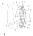
- FIG. 1 is a perspective view of a storage tank with a broken wall showing a floating cover constructed according to the principles of the present invention
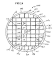
- FIGS. 2A through 2D show a frame structure of the floating cover of FIG. 1;
- FIG. 3 is an exploded perspective view of a floating panel in the floating cover of FIG. 2;
- FIG. 4 is a perspective view of the floating panel of FIG. 3;
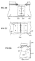
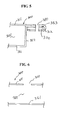
- FIG. 5 is a partial cross-sectional view taken along line 5 - 5 ′ of FIG. 4;
- FIG. 6 is a partial cross-sectional view taken along line 6 - 6 ′ of FIG. 4;
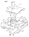
- FIG. 7 is an exploded perspective view of a frame of the structure for the floating cover and a complete floating panel assembled with the frame structure;
- FIG. 8 is a partial perspective view of the floating cover formed by an assembly of a plurality of the floating panels
- FIG. 9 is a partial cross-sectional view taken along line 9 - 9 ′ of FIG. 8;
- FIG. 10 is a partial cross-sectional view taken along line 10 - 10 ′ of FIG. 8;
- FIG. 11A and 11B are partial cross-sectional views of a cap mounted on an inspection port of an upper member of the floating panel constructed according to the principles of the present invention
- FIG. 12 is a partial plan view showing moisture and condensate found in the floating panel through the inspection port.
- FIG. 13 is another embodiment of the floating cover coupled to the frame structure.
- FIG. 1 illustrates a storage tank 100 defining a roof 110 , a bottom 120 , and a hollow cylindrical wall 130 , that is provided with a floating cover 200 constructed according to the principles of the present invention.
- a passage 101 is formed on roof 110 of storage tank 100 and provides an easy access into floating cover 200 contained inside storage tank 100 .
- a plurality of girders 220 , main beams 230 , and cross beams 240 such as “H” shaped steel beams or “I” steel beams, are connected inside a circular rim 210 while a plurality of floating panels 300 are mounted onto respective individual separated openings provided among girders 220 , main beams 230 , and cross beams 240 .
- a central post 250 is installed on a central portion of floating cover 200 , and a plurality of rim legs 261 and main legs 260 are mounted on rim 210 and girders 220 , respectively, in order to support floating cover 200 within storage tank 100 .
- Floating cover 200 floats over the full surface of liquid 150 that fills the space provided between the underside of the floating cover 200 and bottom 120 of storage tank 100 .
- Floating cover 200 moves up and down together with the surface of liquid 150 as a function of the volume of fluid within tank 100 .
- each bottom of floating panels 300 of floating cover 200 is lower than the level of the liquid 150 contained in storage tank 100 , and since roof 110 may be damaged to the point of leaking, moisture and condensate, as well as some of the product stored within the tank, may be present in an inside of one or each of floating panels 300 through damaged seams or a crack usually in the underside of the panel.
- An inspection port 310 formed on each of floating panels 300 that is shown in greater detail provides each of floating panels 300 with the inspection of each of floating panels 300 for leakage without disassembly of any of the adjacent floating panels 300 .
- FIG. 2A shows a plan view of a frame 208 including a rim 210 , a pair of side beams 211 coupled to rim 210 , a plurality of girders 220 connected between side beams 211 , a plurality of main beams 230 coupled between girders 220 , and a plurality of cross beams 240 coupled between main beams 240 and between side beam 211 and rim 210 .
- Central post 250 is mounted on one of girders 220
- main legs 260 and rim legs 261 are mounted on girders 220 and rim 210 , respectively, and protrude toward bottom 120 of storage tank 100 .
- Cross beams 240 are parallel to each other while main beams 230 are perpendicular to both cross beams 240 and girders 220 and are parallel to side beams 211 .
- Openings 291 , 292 , 293 showing a plurality of different shapes are provided by cross beams, girders 220 , and main beams 230 or by rim 210 , cross beams 240 , and side beams 211 .
- the shape of floating panels 300 corresponds to the each of different shape of openings 291 , 292 , 293 .
- FIGS. 2B through 2D show angles 401 , 402 , 403 coupled between girder 220 and main beam 230 , between main beam 230 and cross beam 240 , and between rim 210 and main beam 220 , side beam 211 , or cross beam 212 , 240 , respectively.
- Two webs of girder 220 and main beam 230 are coupled by a pair of angles 401 as shown in FIG. 2B.
- Two webs of main beam 230 and cross beam 240 are spaced-apart from each other and coupled by a pair of angles 402 as shown in FIG. 2C.
- One of main beam 230 , side beam 212 , and cross beam 211 , 240 may coupled to rim 210 by angle 403 .
- a rim extension 210 A is extended upward from rim 210 .
- Floating unit 300 is coupled to a flange of main beam 230 , side beam 211 , or cross beam 211 , 240 .
- FIG. 3 shows floating panel 300 including a lower member 350 defining a bottom 351 , four side walls 352 having a predetermined depth, and extensions 353 extended from each longitudinal end of side walls 352 by a length D2.
- a sealant 370 such as a rubber material, having a length D1 is disposed a bottom side of extension 353 of lower member 350 .
- a upper member 311 includes an inspection port 310 and four end covers 312 , 313 , 314 , 315 disposed outer peripheral sides of upper member 311 to be bent about a broken line 320 A in a direction 322 , 323 , 324 , and 325 , respectively.
- a length D3 of end cover is greater than the sealant 370 and extensions 353 .
- cutout portions 330 are formed at each corner of upper member 311 by a cutout line 320 in order to allow end covers 312 , 313 , 314 , 315 to be bent in the direction 322 , 323 , 324 , 325 , respectively.
- Upper member 311 is placed on extensions 353 of lower member 350 , and end covers 312 , 313 , 314 , 315 are bent in the direction 322 , 323 , 324 , 325 , respectively in order to cover extensions 353 and sealant 270 .
- coupling holes 380 are formed on each side of floating panels 300 as shown in FIG. 4.
- Upper member 311 is spaced apart from bottom 351 of lower member 350 in order to provide a hollow inside 301 which may be communicated with an outside of floating panels 300 through inspection port 301 .
- Sealant 370 is disposed between extensions 353 of lower member 350 and end covers 312 , 313 , 314 , 315 of upper member 311 to make secure against leakage between upper member 311 and lower member 350 .
- upper member 311 is assembled into floating panel 300 with sealant 370 and lower member 350 .
- FIG. 5 shows floating panel 300 having end cover 312 bent in the direction 322 and surrounding extension 353 of lower member 350 and sealant 370 .
- Coupling hole 380 is formed through end cover 312 of upper member 31 1 , extension 353 of lower member 350 , and sealant 370 .
- FIG. 6 shows a cross sectional view taken along 6 - 6 ′ of FIG. 4B.
- Upper member 311 is spaced apart from bottom 351 of lower member 350 , and a sealed hollow inside 301 is provided between upper member 311 and bottom 351 of lower member 350 .
- Each inspection port 3 10 provides a passageway between hollow inside 301 and an outside of floating panel 300 .
- FIGS. 7 and 8 show floating panels 300 inserted into respective openings 391 and coupled to main beams 230 and cross beams 240 .
- a plurality of coupling holes 280 are formed on main beams 230 and cross beams 240 for coupling one of floating panels 300 to main beams 230 and cross beams 240 .
- a plurality of second coupling holes 280 A are formed on main beams 230 and cross beams 240 and spaced apart from first coupling holes 280 .
- Adjacent floating panels 300 are coupled to main beams 230 and cross beams 240 through second coupling holes 280 A.
- An angle 402 is disposed between cross beam 240 and main beam 230 to attach cross beam 240 to main beam 230 .
- a various types of couplers 401 , 402 , 403 may be used for coupling side beams 211 to rim 210 , girders 220 to side beams 211 , main beams 230 to girders 220 , and cross beams 240 either between main beams 220 or between rim 210 and side beams 211 .
- a bolt 285 passes through coupling holes 380 and 280 or 280 A to be coupled to a nut 286 in order to attach each of floating panels 300 to main beams 230 and cross beams 240 .
- FIG. 8 shows the floating panels of FIG. 4 assembled into frame 208 of floating cover 200 .
- Each individual inspection port 310 is shown in each of individual floating panels inserted into respective openings 291 and attached to main beams 230 and cross beams 240 .
- Each one of floating panels is spaced- apart from adjacent floating panels and is coupled to main beams 230 and cross beams 240 without being coupled to the adjacent floating panel and without interfering the assembly of the adjacent floating panels.
- the one of the floating panels 300 does not interfere the adjacent floating panels.
- One of floating panels 300 is replaced with new one without disassembling the adjacent floating panels from main beams 230 and cross beams 240 of frame 208 of floating cover 200 .
- each individual inspection port 310 Since hollow inside 301 of floating panel 300 is communicated with the outside of floating panels 300 through each individual inspection port 310 , bottom 351 of lower member 350 of floating panels 300 can be seen through individual inspection port 310 .
- Individual inspection port 310 is formed on a predetermined position on upper member 311 in order to provide a passageway through which an inspection tool is inserted into hollow inside 301 of floating panel 300 or through bottom 351 of lower member is inspected. Inspection port 310 may be used for sniffing the interior of floating panel 300 with the inspection tool, such as a gas vapor monitor, instead of trying to look through inspection port 310 .
- Individual inspection port 310 may be formed on a central portion or a corner portion of upper member 311 depending on a user's selection.
- inspection port 310 is disposed to allow a user to inspect hollow inside 301 with any of naked eyes and the inspection tool.
- a plurality of inspection ports may be formed on upper member 311 in order to provide the user with the full inspection of the entire inside 301 of floating panels.
- moisture and condensate 399 presented in one of floating panels 300 become visible through inspection port 310 . If one of roof 100 and floating cover 200 is damaged, if the seam of each of floating panels 300 of floating cover 200 is broken, or if the seal of sealant is loosened, moisture and condensate 399 are presented in hollow inside 301 of floating panels 300 and accumulated in bottom 351 of lower member 350 of floating panels 300 . The disassembly of any of floating panels 300 from frame 208 of floating cover 200 is not needed. A user may inspect the presence of the moisture and condensate 399 through inspection port 310 formed on each of floating panels 300 without disassembly of any of floating panels 300 or any of adjacent floating panels 300 . Moreover, the floating cover 200 does not need to be taken out from the storage tank 100 .
- floating panels 300 and frame 208 are separately manufactured in a factory or in different factories located in different locations and are assembled into floating cover 200 inside storage tank 100 , each of floating panels 300 may be individually inspected in the factory and also individually inspected before and after floating panels 300 are assembled. Each inspection of floating panels 300 in both sites of the factory and storage tank 100 before and after the assembly of the floating cover 200 is more great advantageous for the user and manufacturer.
- FIGS. 9 and 10 show a partial cross sectional view taken along lines 9 - 9 ′ and 10 - 10 ′, respectively.
- Floating panel 300 is coupled to main beam 230 by bolt 285 and nut 286 .
- a bush 287 is inserted between bolt 285 and end cover 312 of upper member 311 and may be inserted between end cover 312 and main beam 230 or between main beam 230 and nut 286 .
- each floating panel 300 is coupled to each of horizontal extensions of cross beams 240 and spaced-apart from each other. Because each floating panel includes each individual hollow inside and each individual inspection hole, each individual floating panel can be inspected while adjacent individual floating panel maintains a coupling state to girders 220 , main beams 230 , or cross beams 240 .
- FIGS. 11A and 11B show various types of mechanisms, such as plastic plugs, elastic rubber plugs, adhesive tapes, pipes, etc.
- a removable plug as shown in FIG. 11A is inserted into inspection 8 port 310 in order to close and open inspection port 3 10 of upper member 311 and in order to prevent foreign material from being introduced into hollow inside 301 of floating panel 300 .
- Plastic plug 15 defines a main body 315 A inserted into hollow inside 301 through inspection port 3 10 and having a diameter greater than inspection port 310 , a stopper 31 SB radially extended from main body 31 SA, and a handle protruded from main body 315 A toward an outside of floating unit 300 .
- an additional member 315 A is removably mounted on upper member 311 when upper member 311 is not thick enough to couple an air line or pipe to inspection port 310 .
- a thicker plate 317 couples an air line or pipe to inspection port 310 .
- a thicker plate 317 is coupled to upper member 311 by couplers 319 .
- a sealant 316 is disposed between upper member 311 and plate 317 .
- a removable air line or pipe 318 is fitted into a second port 317 A.
- FIG. 12 shows moisture and condensate 399 contained and accumulated in floating panel 300 and being visible through inspection port 310 .
- Inspection part 310 may have a circular shape, an elongate shape, or an elliptical shape. The shape of plug 315 varies depending on the shape of inspection port 310 .
- FIG. 13 shows another embodiment of the coupling between floating covers 300 and main beam 230 or crossbeam 240 .
- Adjacent floating panels 300 are disposed on respective extensions 241 with respect to a flange 242 of beam 230 , 240 .
- a first sealant 371 is disposed between extension 353 of lower member 350 and both extension 241 and flange 242 of beam 230 , 240 .
- a second sealant 372 is disposed between extension 353 of lower member 350 and end cover 312 of upper member 311 . End cover 312 is bent to cover an auxiliary angle 375 .
- Bolt 285 is coupled to nut 286 through a connecting hole 287 formed on flange 242 , first sealant 371 , extension 353 of lower member, second sealant 372 , end cover 312 of upper member 311 , and auxiliary angle 375 .
- adjacent floating panels 300 are coupled to beam 230 , 240 , the inspection for the presence of vapor, moisture, and condensate is established through inspection port 310 formed on respective floating panels 300 without disassembling adjacent floating panels 300 . Even if one of floating panels 300 is violated, the one of floating panels can be replaced only with the decoupling of bolt 285 and nut 286 from connecting hole 289 . Adjacent floating panels 300 remain in respective openings 291 , 292 , 293 of floating cover 200 during replacement of the one of adjacent floating panels 300 .
- the floating cover or roof is provided with a plurality of floating panels or panels each having respective inspection port constructed according to the principle of the present invention.
- the inspection port damaged or degraded floating panels or panels may be inspected and replaced without decoupling the adjacent floating panels from the floating cover and without taking out the floating cover or roof from the storage tank.
- the entire floating cover does not need to be replaced. Rather, the damaged and degraded one among the floating panels is replaced with a new floating panel after a convenient inspection of the presence of moisture and condensate trapped in the trough or the inside of each floating panels through each inspection port formed on each of floating panels or panels.
Landscapes
- Engineering & Computer Science (AREA)
- Mechanical Engineering (AREA)
- Examining Or Testing Airtightness (AREA)
Abstract
A floating cover or roof having a plurality of floating panels or panels is provided. The floating cover disposed in a storage tank includes a frame having a plurality of openings, the floating panels mounted into the respective openings, an inspection port formed on an upper member of the floating panel and communicated with an inside of the floating panel. The inspection port provides the inspection of presence of moisture, vapor, and condensate trapped in the inside of each of the floating panels without disassembly of adjacent floating panels and also provides the replacement of damaged or degraded one among the floating panels without taking out the internal floating roof from the storage tank.
Description
- 1. Field of the Invention
- The present invention relates to a floating cover for a liquid storage tank, and more particularly, to a liquid surface contact internal floating cover constructed with a plurality of floating panels and process for monitoring leaks within each of the floating panels.
- 2. Description of the Background Art
- Floating covers have previously been used inside cylindrical liquid storage tanks to ride vertically along the cylindrical wall of the tanks between the roof and bottom as the volume of fluid held by the tank varies. Typically, the floating cover floats above the liquid and moves up and down depending on the amount of the liquid. A plurality of buoyant panels or honeycomb type pans, are assembled to form the floating cover. This conventional floating cover, however, is expensive to manufacture and erect inside the frame of the tank. Accordingly, periodic inspection and maintenance of the cover is desirable in order to obtain the full life of the cover.
- The current design for full surface contact floating covers uses honeycomb panels that are manufactured by bonding an aluminum channel frame to the honeycomb panel. The honeycomb panel may have all sealed cells or all interconnected cells. If some of the cells of an individually sealed honeycomb are opened to invasion of the product held by the tank, there is currently no way of detecting the invasion except by observation of the escaped product as it drips out of the panel after the tank has been taken out of service and emptied. The trapped liquid will however, slowly drip out of the panel and present a grave safety hazard to the maintenance people working within the interior of the tank. If a cell of an interconnecting cell type of honeycomb panel is violated, then all cells are violated, making it near impossible to find the original leaking cell. The whole panel must be replaced.
- The owners and managers of tanks must periodically inspect the interior of the tank and make repairs. This entails a removal of the contents of the tank, a purging of gaseous phase vapors from the interior of the tank, an introduction of ambient atmospheric air into the interior of the tank and continuous or at least intermittent monitoring of the atmosphere within the interior of the tank.
- The owner of the tank needs assurance that before personnel enter the interior of the empty tank, and that while work (particularly using arc or open flame torches) is performed within the interior of the tank, that the tank has been completely emptied and cleaned, and is safe for both the personnel and the type of work being performed. This assurance requires that there be no remaining hazardous pockets of the contents of the tank within the floating roof.
- Currently, contemporary designers of buoyant panels provide no convenient technique for detecting the presence of moisture and condensate within individual buoyant panels.
- It is an object of the present invention to provide an improved floating roof.
- It is another object to provide a floating roof and process for detecting the presence of vapor, moisture, or condensate which indicates leakage and the onset of deterioration of the integrity of the roof.
- It is still another object to provide a floating roof assembled from multiple panels and a process for inspecting individual panels for the onset of deterioration.
- It is yet another object to provide a floating cover able to remove and replace individual floating panels of a frame for the floating cover without interfering with the integrity of adjacent floating panels.
- It is still yet another object to provide a floating cover that permits inspection of leakage of each of the floating panels forming the floating cover without disassembly of the floating cover.
- It is a further object to provide a full liquid surface contact internal floating cover constructed with individual floatation panels that may be checked for leakage from the top side of the cover while the tank is in service.
- It is still another object to provide a full liquid surface contact internal floating cover that accommodates vapor sampling of the entire interior volume of the floatation panels.
- It is yet a further object to provide a full liquid surface contact internal floating cover assembled from floatation panels set into the frame of the cover from the top side of the floating roof.
- It is a still yet farther object to provide a full liquid surface contact internal floating cover assembled from a plurality of floatation panels, with adjacent panels allowing unrestricted removal of individual floatation panels.
- It is also an object to provide a full liquid surface contact internal floating cover with a frame for support of discrete floatation panels that is constructed from rigid structural members.
- It is also an object to provide a full liquid surface contact internal floating cover constructed from a plurality of floatation panels that are not relied upon for the structural rigidity of the cover and therefore are not subjected to failure due to metal fatigue.
- It is also an object to provide a full liquid surface contact internal floating cover constructed from a plurality of floatation panels that may be leak tested at the point of manufacture as well as in the field after assembly of the cover.
- It is also object to provide a floating cover that allows individual panels within the floating cover to be inspected without detaching either the particular panel being inspected or any adjacent panel from the floating cover.
- These and other objects may be achieved by providing a storage tank with a floating cover including a frame having a plurality of openings, a plurality of floating panels mounted into the respective openings in the frame, an inspection port formed on an upper member of each of the floating panels that when opened, communicates with an hollow cavity interior of the floating panel, and a cap covering the inspection port of the floating panel. The presence of moisture and condensate contained in any of floating panels can be visually detected through the inspection port of the each of the floating panels without disassembling any of the floating panels or without removing the entire floating cover from the storage tank.
- A more complete appreciation of this invention, and many of the attendant advantages thereof, will be readily apparent as the same becomes better understood by reference to the following detailed description when considered in conjunction with the accompanying drawings in which like reference symbols indicate the same or similar components, wherein:
- FIG. 1 is a perspective view of a storage tank with a broken wall showing a floating cover constructed according to the principles of the present invention;
- FIGS. 2A through 2D show a frame structure of the floating cover of FIG. 1;
- FIG. 3 is an exploded perspective view of a floating panel in the floating cover of FIG. 2;
- FIG. 4 is a perspective view of the floating panel of FIG. 3;
- FIG. 5 is a partial cross-sectional view taken along line 5-5′ of FIG. 4;
- FIG. 6 is a partial cross-sectional view taken along line 6-6′ of FIG. 4;
- FIG. 7 is an exploded perspective view of a frame of the structure for the floating cover and a complete floating panel assembled with the frame structure;
- FIG. 8 is a partial perspective view of the floating cover formed by an assembly of a plurality of the floating panels;
- FIG. 9 is a partial cross-sectional view taken along line 9-9′ of FIG. 8;
- FIG. 10 is a partial cross-sectional view taken along line 10-10′ of FIG. 8;
- FIG. 11A and 11B are partial cross-sectional views of a cap mounted on an inspection port of an upper member of the floating panel constructed according to the principles of the present invention;
- FIG. 12 is a partial plan view showing moisture and condensate found in the floating panel through the inspection port; and.
- FIG. 13 is another embodiment of the floating cover coupled to the frame structure.
- Turning now to the drawings, FIG. 1 illustrates a
storage tank 100 defining a roof 110, abottom 120, and a hollowcylindrical wall 130, that is provided with afloating cover 200 constructed according to the principles of the present invention. A passage 101 is formed on roof 110 ofstorage tank 100 and provides an easy access into floatingcover 200 contained insidestorage tank 100. A plurality ofgirders 220,main beams 230, andcross beams 240, such as “H” shaped steel beams or “I” steel beams, are connected inside acircular rim 210 while a plurality offloating panels 300 are mounted onto respective individual separated openings provided amonggirders 220,main beams 230, andcross beams 240. Acentral post 250 is installed on a central portion offloating cover 200, and a plurality ofrim legs 261 andmain legs 260 are mounted onrim 210 andgirders 220, respectively, in order to support floatingcover 200 withinstorage tank 100. Floating cover 200 floats over the full surface ofliquid 150 that fills the space provided between the underside of thefloating cover 200 andbottom 120 ofstorage tank 100. Floatingcover 200 moves up and down together with the surface ofliquid 150 as a function of the volume of fluid withintank 100. - Since each bottom of
floating panels 300 offloating cover 200 is lower than the level of theliquid 150 contained instorage tank 100, and since roof 110 may be damaged to the point of leaking, moisture and condensate, as well as some of the product stored within the tank, may be present in an inside of one or each offloating panels 300 through damaged seams or a crack usually in the underside of the panel. Aninspection port 310 formed on each offloating panels 300 that is shown in greater detail provides each offloating panels 300 with the inspection of each offloating panels 300 for leakage without disassembly of any of the adjacentfloating panels 300. - FIG. 2A shows a plan view of a
frame 208 including arim 210, a pair ofside beams 211 coupled torim 210, a plurality ofgirders 220 connected betweenside beams 211, a plurality ofmain beams 230 coupled betweengirders 220, and a plurality ofcross beams 240 coupled betweenmain beams 240 and betweenside beam 211 andrim 210.Central post 250 is mounted on one ofgirders 220, andmain legs 260 andrim legs 261 are mounted ongirders 220 andrim 210, respectively, and protrude towardbottom 120 ofstorage tank 100. Cross beams 240 are parallel to each other whilemain beams 230 are perpendicular to bothcross beams 240 andgirders 220 and are parallel to side beams 211.Openings girders 220, andmain beams 230 or byrim 210, cross beams 240, and side beams 211. The shape of floatingpanels 300 corresponds to the each of different shape ofopenings - FIGS. 2B through 2D show angles 401, 402, 403 coupled between
girder 220 andmain beam 230, betweenmain beam 230 andcross beam 240, and betweenrim 210 andmain beam 220,side beam 211, orcross beam girder 220 andmain beam 230 are coupled by a pair ofangles 401 as shown in FIG. 2B. Two webs ofmain beam 230 andcross beam 240 are spaced-apart from each other and coupled by a pair ofangles 402 as shown in FIG. 2C. One ofmain beam 230,side beam 212, andcross beam rim 210 byangle 403. Arim extension 210A is extended upward fromrim 210. Floatingunit 300 is coupled to a flange ofmain beam 230,side beam 211, orcross beam - FIG. 3
shows floating panel 300 including alower member 350 defining a bottom 351, fourside walls 352 having a predetermined depth, andextensions 353 extended from each longitudinal end ofside walls 352 by a length D2. Asealant 370, such as a rubber material, having a length D1 is disposed a bottom side ofextension 353 oflower member 350. Aupper member 311 includes aninspection port 310 and four end covers 312, 313, 314, 315 disposed outer peripheral sides ofupper member 311 to be bent about a broken line 320A in adirection sealant 370 andextensions 353. Fourcutout portions 330 are formed at each corner ofupper member 311 by acutout line 320 in order to allow end covers 312, 313, 314, 315 to be bent in thedirection -
Upper member 311 is placed onextensions 353 oflower member 350, and end covers 312, 313, 314, 315 are bent in thedirection extensions 353 and sealant 270. Onceupper member 311,lower member 350, andsealant 370 are assembled into floatingpanel 300, coupling holes 380 are formed on each side of floatingpanels 300 as shown in FIG. 4.Upper member 311 is spaced apart frombottom 351 oflower member 350 in order to provide a hollow inside 301 which may be communicated with an outside of floatingpanels 300 throughinspection port 301.Sealant 370 is disposed betweenextensions 353 oflower member 350 and end covers 312, 313, 314, 315 ofupper member 311 to make secure against leakage betweenupper member 311 andlower member 350. In FIG. 4,upper member 311 is assembled into floatingpanel 300 withsealant 370 andlower member 350. - FIG. 5
shows floating panel 300 having end cover 312 bent in thedirection 322 and surroundingextension 353 oflower member 350 andsealant 370. Couplinghole 380 is formed throughend cover 312 ofupper member 31 1,extension 353 oflower member 350, andsealant 370. FIG. 6 shows a cross sectional view taken along 6-6′ of FIG. 4B.Upper member 311 is spaced apart frombottom 351 oflower member 350, and a sealed hollow inside 301 is provided betweenupper member 311 andbottom 351 oflower member 350. Each inspection port 3 10 provides a passageway between hollow inside 301 and an outside of floatingpanel 300. - FIGS. 7 and 8
show floating panels 300 inserted intorespective openings 391 and coupled tomain beams 230 and cross beams 240. A plurality ofcoupling holes 280 are formed onmain beams 230 and crossbeams 240 for coupling one of floatingpanels 300 tomain beams 230 and cross beams 240. A plurality of second coupling holes 280A are formed onmain beams 230 and crossbeams 240 and spaced apart from first coupling holes 280. Adjacent floatingpanels 300 are coupled tomain beams 230 and crossbeams 240 through second coupling holes 280A. Anangle 402 is disposed betweencross beam 240 andmain beam 230 to attachcross beam 240 tomain beam 230. A various types ofcouplers side beams 211 torim 210,girders 220 toside beams 211,main beams 230 togirders 220, and crossbeams 240 either betweenmain beams 220 or betweenrim 210 and side beams 211. Abolt 285 passes throughcoupling holes nut 286 in order to attach each of floatingpanels 300 tomain beams 230 and cross beams 240. - FIG. 8 shows the floating panels of FIG. 4 assembled into
frame 208 of floatingcover 200. Eachindividual inspection port 310 is shown in each of individual floating panels inserted intorespective openings 291 and attached tomain beams 230 and cross beams 240. Each one of floating panels is spaced- apart from adjacent floating panels and is coupled tomain beams 230 and crossbeams 240 without being coupled to the adjacent floating panel and without interfering the assembly of the adjacent floating panels. During attaching one of the floatingpanel 300 tomain beams 230 and crossbeams 240 or during detaching one the floatingpanel 300 frommain beams 230 and crossbeams 240, the one of the floatingpanels 300 does not interfere the adjacent floating panels. One of floatingpanels 300 is replaced with new one without disassembling the adjacent floating panels frommain beams 230 and crossbeams 240 offrame 208 of floatingcover 200. - Since hollow inside 301 of floating
panel 300 is communicated with the outside of floatingpanels 300 through eachindividual inspection port 310,bottom 351 oflower member 350 of floatingpanels 300 can be seen throughindividual inspection port 310.Individual inspection port 310 is formed on a predetermined position onupper member 311 in order to provide a passageway through which an inspection tool is inserted into hollow inside 301 of floatingpanel 300 or throughbottom 351 of lower member is inspected.Inspection port 310 may be used for sniffing the interior of floatingpanel 300 with the inspection tool, such as a gas vapor monitor, instead of trying to look throughinspection port 310.Individual inspection port 310 may be formed on a central portion or a corner portion ofupper member 311 depending on a user's selection. Therefore,inspection port 310 is disposed to allow a user to inspect hollow inside 301 with any of naked eyes and the inspection tool. A plurality of inspection ports may be formed onupper member 311 in order to provide the user with the full inspection of the entire inside 301 of floating panels. - In FIG. 8, moisture and
condensate 399 presented in one of floatingpanels 300 become visible throughinspection port 310. If one ofroof 100 and floatingcover 200 is damaged, if the seam of each of floatingpanels 300 of floatingcover 200 is broken, or if the seal of sealant is loosened, moisture andcondensate 399 are presented in hollow inside 301 of floatingpanels 300 and accumulated inbottom 351 oflower member 350 of floatingpanels 300. The disassembly of any of floatingpanels 300 fromframe 208 of floatingcover 200 is not needed. A user may inspect the presence of the moisture andcondensate 399 throughinspection port 310 formed on each of floatingpanels 300 without disassembly of any of floatingpanels 300 or any of adjacent floatingpanels 300. Moreover, the floatingcover 200 does not need to be taken out from thestorage tank 100. - Since the coupling of one floating panel to beams does not affect the coupling of the adjacent floating panels to beams of
frame 208, the processing time for assembling floating panels to beams is shortened, and the cost for manufacturing floating panels and assembling the floating cover is significantly reduced. Moreover, it is very convenient and very advantageous for a user to replace a damaged floating panel with a new floating panel, thereby reducing the time and cost for the replacement of the damaged floating panels. - Since floating
panels 300 andframe 208 are separately manufactured in a factory or in different factories located in different locations and are assembled into floatingcover 200 insidestorage tank 100, each of floatingpanels 300 may be individually inspected in the factory and also individually inspected before and after floatingpanels 300 are assembled. Each inspection of floatingpanels 300 in both sites of the factory andstorage tank 100 before and after the assembly of the floatingcover 200 is more great advantageous for the user and manufacturer. - FIGS. 9 and 10 show a partial cross sectional view taken along lines 9-9′ and 10-10′, respectively. Floating
panel 300 is coupled tomain beam 230 bybolt 285 andnut 286. Abush 287 is inserted betweenbolt 285 andend cover 312 ofupper member 311 and may be inserted betweenend cover 312 andmain beam 230 or betweenmain beam 230 andnut 286. - Two adjacent floating
panels 300 are coupled to each of horizontal extensions ofcross beams 240 and spaced-apart from each other. Because each floating panel includes each individual hollow inside and each individual inspection hole, each individual floating panel can be inspected while adjacent individual floating panel maintains a coupling state togirders 220,main beams 230, or cross beams 240. - FIGS. 11A and 11B show various types of mechanisms, such as plastic plugs, elastic rubber plugs, adhesive tapes, pipes, etc. A removable plug as shown in FIG. 11A is inserted into inspection 8
port 310 in order to close and open inspection port 3 10 ofupper member 311 and in order to prevent foreign material from being introduced into hollow inside 301 of floatingpanel 300. Plastic plug 15 defines amain body 315A inserted into hollow inside 301 through inspection port 3 10 and having a diameter greater thaninspection port 310, astopper 31 SB radially extended frommain body 31 SA, and a handle protruded frommain body 315A toward an outside of floatingunit 300. In FIG. 11B, anadditional member 315A is removably mounted onupper member 311 whenupper member 311 is not thick enough to couple an air line or pipe toinspection port 310. Athicker plate 317 couples an air line or pipe toinspection port 310. Athicker plate 317 is coupled toupper member 311 bycouplers 319. Asealant 316 is disposed betweenupper member 311 andplate 317. A removable air line orpipe 318 is fitted into asecond port 317A. FIG. 12 shows moisture andcondensate 399 contained and accumulated in floatingpanel 300 and being visible throughinspection port 310.Inspection part 310 may have a circular shape, an elongate shape, or an elliptical shape. The shape ofplug 315 varies depending on the shape ofinspection port 310. - FIG. 13 shows another embodiment of the coupling between floating
covers 300 andmain beam 230 orcrossbeam 240. Adjacent floatingpanels 300 are disposed onrespective extensions 241 with respect to a flange 242 ofbeam first sealant 371 is disposed betweenextension 353 oflower member 350 and bothextension 241 and flange 242 ofbeam second sealant 372 is disposed betweenextension 353 oflower member 350 andend cover 312 ofupper member 311.End cover 312 is bent to cover anauxiliary angle 375.Bolt 285 is coupled tonut 286 through a connectinghole 287 formed on flange 242,first sealant 371,extension 353 of lower member,second sealant 372,end cover 312 ofupper member 311, andauxiliary angle 375. Although adjacent floatingpanels 300 are coupled tobeam inspection port 310 formed on respective floatingpanels 300 without disassembling adjacent floatingpanels 300. Even if one of floatingpanels 300 is violated, the one of floating panels can be replaced only with the decoupling ofbolt 285 andnut 286 from connecting hole 289. Adjacent floatingpanels 300 remain inrespective openings cover 200 during replacement of the one of adjacent floatingpanels 300. - As mentioned above, the floating cover or roof is provided with a plurality of floating panels or panels each having respective inspection port constructed according to the principle of the present invention. With the inspection port, damaged or degraded floating panels or panels may be inspected and replaced without decoupling the adjacent floating panels from the floating cover and without taking out the floating cover or roof from the storage tank. The entire floating cover does not need to be replaced. Rather, the damaged and degraded one among the floating panels is replaced with a new floating panel after a convenient inspection of the presence of moisture and condensate trapped in the trough or the inside of each floating panels through each inspection port formed on each of floating panels or panels.
- Although the preferred embodiment of the present invention has been shown and described, it will be appreciated by those skilled in the art that changes may be made in these embodiments without departing from the principles and spirit of the invention, the scope of which is defined in the claims and their equivalents.
Claims (18)
1. A floating cover in a storage tank, comprising:
a frame having a plurality of innerconnected members forming a plurality of discrete openings, said frame defining a full surface liquid contact cover floating above a surface of any liquid stored in the storage tank;
a plurality of floating panel members each conforming in a shape to a different corresponding one of said openings and coupling to said innerconnected members, said floating panel members each having an upper pan and a lower pan attached to an exterior rim of said upper pan, said floating panel members each having a hollow inside formed between said upper and lower pans; and
an inspection port formed on said upper pan of each of said floating panel members, providing a visual inspection into said hollow inside from top side of said floating panel member.
2. The floating cover of claim 1 , further comprising a sealant disposed between said exterior rim of said upper pan and said lower pan.
3. The floating cover of claim 2 , wherein moisture or condensate permeated through inner edges formed between said upper pan and said lower pan and condensed on an inner surface of said upper pan drips on an inner surface of said lower pan when said sealant is degraded
4. The floating cover of claim 3 , wherein the moist are or condensate is visible from said top side of said floating panel member through said inspection port.
5. The floating cover of claim 1 , wherein one of said floating panel members is coupled to said frame without interfering the assembly of adjacent floating panel members which are inserted into each corresponding opening formed on said frame and are coupled to said frame.
6. The floating cover of claim 1 , wherein one of said floating panel members is detached from said frame without detaching any of adjacent floating panel member from said frame.
7. A floating cover in a storage tank, comprising:
a frame having a rim and a plurality of beams arranged within and coupled to said rim to provide a plurality of separate and individual openings;
a plurality of floating panels each inserted into each corresponding one of said separate and individual openings and coupled to said beams or rims, said floating panels spaced-apart from each other, said floating panels each having an individual sealed hollow inside; and
an inspection port formed on each of said floating panels and communicated with said individual sealed hollow inside.
8. The floating cover of claim 7 , with said floating panels each coupled to said beams without being coupled to an adjacent floating panel.
9. The floating cover of claim 7 , wherein moisture and condense trapped in said hollow inside of each floating panel is seen through said inspection port.
10 The floating cover of claim 7 , with said floating panels each comprising an upper member and a lower member coupled on a lower side of a rim of said upper member, said hollow inside formed between said upper member and said lower member, and a sealant disposed between said rim of said upper member and said lower member.
11. The floating cover of claim 10 , wherein said lower member is visible through said inspection port from outside said floating cover.
12. The floating cover of claim 10 , with said hole formed on said upper member.
13. The floating cover of claim 10 , with said lower member defining a bottom, four sidewalls raised from said bottom by a predetermined height, and four extensions each extended from respective sidewalls and coupled to said upper member.
14. The floating cover of claim 10 , with said upper member including four end covers bent toward a bottom side of each extension of said lower member and clipping and covering said corresponding extension of said lower member.
15. A process for a floating cover, comprising the steps of:
providing a frame having a plurality of beams fabricated within said frame, said beams providing a plurality of separate and individual openings; and
providing a plurality of floating panels each having an upper panel, a lower panel coupled to said upper panel, an individual sealed hollow formed between said upper panel and said lower panel, and an individual inspection hole formed on said upper panel and communicated with said hollow; and
coupling each one of said floating panels to said beams after each of said floating panels is placed into corresponding one of said openings without interfering the coupling of adjacent floating panels.
16. The process of claim 15 , wherein said inspection port enabling a user to inspect said hollow of said floating panels from an outside of said floating panels.
17. The process of claim 15 , further comprising a sealant disposed between said upper panel and said lower panel.
18. The process of claim 17 , wherein moisture and condensate permeated through inner edges between said upper panel and said lower panel through said sealant and condensed on an inner surface of said upper panel drips on an inner surface of said lower panel and is visible through said inspection port from outside of said floating cover.
Priority Applications (2)
| Application Number | Priority Date | Filing Date | Title |
|---|---|---|---|
| US09/877,253 US6505445B2 (en) | 2001-06-11 | 2001-06-11 | Floating cover |
| US10/230,070 US6922956B2 (en) | 2001-06-11 | 2002-08-29 | Floating cover |
Applications Claiming Priority (1)
| Application Number | Priority Date | Filing Date | Title |
|---|---|---|---|
| US09/877,253 US6505445B2 (en) | 2001-06-11 | 2001-06-11 | Floating cover |
Related Child Applications (1)
| Application Number | Title | Priority Date | Filing Date |
|---|---|---|---|
| US10/230,070 Continuation-In-Part US6922956B2 (en) | 2001-06-11 | 2002-08-29 | Floating cover |
Publications (2)
| Publication Number | Publication Date |
|---|---|
| US20020184838A1 true US20020184838A1 (en) | 2002-12-12 |
| US6505445B2 US6505445B2 (en) | 2003-01-14 |
Family
ID=25369558
Family Applications (1)
| Application Number | Title | Priority Date | Filing Date |
|---|---|---|---|
| US09/877,253 Expired - Lifetime US6505445B2 (en) | 2001-06-11 | 2001-06-11 | Floating cover |
Country Status (1)
| Country | Link |
|---|---|
| US (1) | US6505445B2 (en) |
Cited By (3)
| Publication number | Priority date | Publication date | Assignee | Title |
|---|---|---|---|---|
| US20090126309A1 (en) * | 2007-11-15 | 2009-05-21 | Thomas Edward Lyness | Methods and systems for assembling a tower |
| CN114249039A (en) * | 2020-09-23 | 2022-03-29 | 代纳玻璃增强塑料公司 | Cross-point separator for use in floating cover |
| CN117508913A (en) * | 2023-09-01 | 2024-02-06 | 江苏海洋大学 | Floating disc with color-changing display function |
Families Citing this family (6)
| Publication number | Priority date | Publication date | Assignee | Title |
|---|---|---|---|---|
| US5400549A (en) * | 1993-10-22 | 1995-03-28 | Morgan; William D. | Insulated removable pond cover |
| US6922956B2 (en) * | 2001-06-11 | 2005-08-02 | Petrex, Inc. | Floating cover |
| US20040188438A1 (en) * | 2003-03-26 | 2004-09-30 | King Richard P. | Full contact floating roof |
| US20130134611A1 (en) * | 2011-11-30 | 2013-05-30 | Patrick Harvey Colclasure | Free-floating weighted shield for preventing sunlight exposure and algae growth in a cooling tower basin |
| US11548725B2 (en) | 2013-03-15 | 2023-01-10 | Industrial & Environmental Concepts, Inc. | Cover systems, tank covering methods, and pipe retention systems |
| US11141952B2 (en) | 2015-04-06 | 2021-10-12 | Industrial & Environmental Concepts, Inc. | Sludge covers, sludge management systems, and related methods |
Family Cites Families (15)
| Publication number | Priority date | Publication date | Assignee | Title |
|---|---|---|---|---|
| US2237461A (en) | 1937-12-02 | 1941-04-08 | John J Tokheim | Liquid level gauge equipment |
| US3374918A (en) | 1966-01-25 | 1968-03-26 | Olin Mathieson | Floating deck for storage tank |
| US3724704A (en) | 1971-04-13 | 1973-04-03 | Pittsburgh Des Moines Steel | Floating roof having uniformly distributed buoyancy means |
| US3774799A (en) | 1971-11-03 | 1973-11-27 | Gen Am Transport | Sectional floating roof and method of forming same |
| US3910452A (en) | 1972-12-01 | 1975-10-07 | Sandborn Edmund | Floating cover for a storage tank |
| US4036394A (en) * | 1973-03-19 | 1977-07-19 | Aerojet-General Corporation | Floating roof for liquid storage tanks |
| US3980199A (en) | 1974-08-16 | 1976-09-14 | Globe Linings, Inc. | Gas venting for floating cover |
| US3944113A (en) | 1974-11-18 | 1976-03-16 | General American Transportation Corporation | Floating roof |
| US3972444A (en) * | 1975-04-10 | 1976-08-03 | Pittsburgh Des Moines Steel Company | Floating roof having uniformly distributed buoyancy means |
| US4202460A (en) | 1978-04-13 | 1980-05-13 | Imbeault Fernand A | Sectional floating cover |
| US4213280A (en) | 1978-09-06 | 1980-07-22 | Novaro Investments Limited | Modular unit for the construction of floating decks of liquid storage tanks |
| US4243151A (en) | 1979-07-02 | 1981-01-06 | Bruening Robert A | Floating roof penetrations with reduced vapor space seal |
| US5533640A (en) | 1993-05-14 | 1996-07-09 | Hmt, Inc. | Floating roof |
| US5704509A (en) | 1995-05-08 | 1998-01-06 | Allentech, Inc. | Full contact floating roof |
| BR9704844A (en) | 1997-02-03 | 1999-09-14 | Petroleo Brasileiro Sa | Non-structural floating roof with high elasticity for liquid storage tanks. |
-
2001
- 2001-06-11 US US09/877,253 patent/US6505445B2/en not_active Expired - Lifetime
Cited By (4)
| Publication number | Priority date | Publication date | Assignee | Title |
|---|---|---|---|---|
| US20090126309A1 (en) * | 2007-11-15 | 2009-05-21 | Thomas Edward Lyness | Methods and systems for assembling a tower |
| US8763313B2 (en) * | 2007-11-15 | 2014-07-01 | General Electric Company | Methods and systems for assembling a tower |
| CN114249039A (en) * | 2020-09-23 | 2022-03-29 | 代纳玻璃增强塑料公司 | Cross-point separator for use in floating cover |
| CN117508913A (en) * | 2023-09-01 | 2024-02-06 | 江苏海洋大学 | Floating disc with color-changing display function |
Also Published As
| Publication number | Publication date |
|---|---|
| US6505445B2 (en) | 2003-01-14 |
Similar Documents
| Publication | Publication Date | Title |
|---|---|---|
| US4895272A (en) | Liquid storage system | |
| US5562047A (en) | Modular spill deck | |
| US6505445B2 (en) | Floating cover | |
| US5285914A (en) | Above-grade storage vault | |
| US8328040B2 (en) | Multiple-walled storage tank | |
| US6922956B2 (en) | Floating cover | |
| US5509562A (en) | Floating roof | |
| US6739469B1 (en) | Water tank | |
| US4912966A (en) | Total containment means for storage tank systems | |
| JP2010014014A (en) | Engine-driven working machine | |
| US20030042256A1 (en) | Floating cover | |
| KR101422783B1 (en) | Storage tank with lining panel | |
| EP0752555B1 (en) | Protecture container for the underground installation of tanks for pressurized, liquefied gas | |
| CN212333531U (en) | Partition type assembled inner floating roof made of stainless steel | |
| US7240804B2 (en) | Full contact floating roof | |
| US5474207A (en) | Liquid storage tank with glass reinforced plastic tie rods | |
| CN205938008U (en) | Hydraulic safety valve | |
| KR200441829Y1 (en) | Gas storage tank | |
| CN107701767A (en) | hydraulic safety valve | |
| KR102295700B1 (en) | Oil storage tank floating roof leg system | |
| GB2177149A (en) | Storage container for liquids | |
| KR100318586B1 (en) | Water tank | |
| KR101840798B1 (en) | Cover apparatus of pipe connection portion | |
| CN220303509U (en) | A mounting hole structure and its mounting body | |
| US20050205580A1 (en) | Reverse flange collar adapter and reverse flange collar |
Legal Events
| Date | Code | Title | Description |
|---|---|---|---|
| AS | Assignment |
Owner name: PETREX, INC., PENNSYLVANIA Free format text: ASSIGNMENT OF ASSIGNORS INTEREST;ASSIGNORS:JOHNSON, BURTON M.;WAGNER, WILLIAM L.;REEL/FRAME:012154/0435 Effective date: 20010830 |
|
| STCF | Information on status: patent grant |
Free format text: PATENTED CASE |
|
| FEPP | Fee payment procedure |
Free format text: PAYOR NUMBER ASSIGNED (ORIGINAL EVENT CODE: ASPN); ENTITY STATUS OF PATENT OWNER: SMALL ENTITY |
|
| FPAY | Fee payment |
Year of fee payment: 4 |
|
| FPAY | Fee payment |
Year of fee payment: 8 |
|
| FPAY | Fee payment |
Year of fee payment: 12 |