US2000592A - Support - Google Patents
Support Download PDFInfo
- Publication number
- US2000592A US2000592A US655820A US65582033A US2000592A US 2000592 A US2000592 A US 2000592A US 655820 A US655820 A US 655820A US 65582033 A US65582033 A US 65582033A US 2000592 A US2000592 A US 2000592A
- Authority
- US
- United States
- Prior art keywords
- cradle
- base
- torch
- stand
- supporting
- Prior art date
- Legal status (The legal status is an assumption and is not a legal conclusion. Google has not performed a legal analysis and makes no representation as to the accuracy of the status listed.)
- Expired - Lifetime
Links
- XEEYBQQBJWHFJM-UHFFFAOYSA-N Iron Chemical compound [Fe] XEEYBQQBJWHFJM-UHFFFAOYSA-N 0.000 description 20
- 238000005476 soldering Methods 0.000 description 12
- 229910052742 iron Inorganic materials 0.000 description 10
- 238000010276 construction Methods 0.000 description 5
- 238000009408 flooring Methods 0.000 description 4
- 238000006073 displacement reaction Methods 0.000 description 2
- 230000004048 modification Effects 0.000 description 2
- 238000012986 modification Methods 0.000 description 2
- 238000001816 cooling Methods 0.000 description 1
- 239000002023 wood Substances 0.000 description 1
Images

Classifications
-
- B—PERFORMING OPERATIONS; TRANSPORTING
- B23—MACHINE TOOLS; METAL-WORKING NOT OTHERWISE PROVIDED FOR
- B23K—SOLDERING OR UNSOLDERING; WELDING; CLADDING OR PLATING BY SOLDERING OR WELDING; CUTTING BY APPLYING HEAT LOCALLY, e.g. FLAME CUTTING; WORKING BY LASER BEAM
- B23K3/00—Tools, devices, or special appurtenances for soldering, e.g. brazing, or unsoldering, not specially adapted for particular methods
- B23K3/02—Soldering irons; Bits
- B23K3/027—Holders for soldering irons
Definitions
- This invention relates generally to stands and refers more particularly. to a portable stand for. supporting soldering equipment.
- One of the essential objects of the invention .5. isv to provide a stand of this type wherein a cradle is providedfor supporting soldering equipment such as a blow'torch safely. while lit and while cooling.
- Another object is to provide a stand wherein the cradle is supported upon an arched base having substantially parallel runners for en.--
- Another object is to provide a stand whereinportions of the arched base are fashioned tolhold: the torch in the cradle.
- Another object is to provide a stand wherein the holding means. and arched base are con structed and arranged in such a way that the torch will be prevented from wobbling orv snaking over the ground, flooring, etc.
- vAnother object is to provide astand wherein the arched base aforesaidis constructed so that it. may be readily secured to a horizontal, inclined. or upright surface as desired.
- Another object is to provideastandwherein.
- soldering iron so thatthe soldering point thereof may be heated by flames issuing .from' the blow torch in the cradle.
- Figure 1 is a top plan view of a stand embodying our invention and showing a torch applied thereto;
- Figure 2 is a side elevation of the construction illustrated in Figure 1;
- Figure 3 is a perspective view of the stand
- Figure 4 is a view similar to Figure l but showing a slight modification
- Figure 5 is a side elevation of the construction illustrated in Figure 4.
- Figure 6 is a perspective View of the stand illustrated in Figures 4 and 5.
- the cradle A is formed from a single length of heavy gauge wire and has a substantially fiat base portion I, upwardly inclined portions 2 and 3, respectively, at opposite ends of said base portion, and depending U-shaped end portions 4 and 5, respectively, at the upper ends of said inclined portions.
- the inclined portion 2 is shorter than the inclined portion 3 and the depending portion 5 is longer than the depending portion-4.
- the base B is also formed from a single length of wireand has laterally spaced sides 6 and I and longitudinally curved sub.- stantially triangular-shaped legs 6* and .l Preferably this base crosses and is welded to the base I of the cradle.
- the ground engaging. portions ⁇ 6* and'l respectively of the legs 6 and T arepreferably parallel and form runways for the stand.
- Portions 8- and 9, respectively, of the base formed by the free ends of'the wire extend upwardly at the base I andare fashioned asshown to -hold' a torch such as X in the cradle A.
- the torch X may be easily and quickly placedlinor removed from the cradle A between the'holding portions 8 and 9 and the stand may be -readily secured to or moved over any suitable surface.
- the construction of thestand is suchthat the torch'will be prevented from wobbling or snakingwhenthestand is moved, hence may be moved about safely while in the cradle
- the construction is such that the flames issuingfrom the torch when lit will be directed away 'from 'theground or flooring, hence the equipment maybe used safely on wood flooring.
- extend upwardly from the cradle A and base B, respectively, and have depending substantially V- shaped portions 22 and 23, respectively, at their upper ends for supporting a soldering iron such as Z.
- extends slightly above the U-shaped portion 20 and the V-shaped portion 23 is at a higher point that the V-shaped portion 22 so that the soldering iron Z will be supported in a somewhat inclined position with its soldering point 25 just above and adapted to be heated by flames issuing from the mixing chamber 26 of the torch.
- a stand of the class described comprising an arched base, a cradle for receiving and supporting a blow torch extending across. and secured to said base, and means projecting from the base into the cradle for holding the blow torch against accidental displacement.
- a stand of the class described comprising a base, a cradle for receiving and supporting a blow torch extending across and secured to said base, and means for holding the blow torch in the cradle including projections on the base formed to permit substantially vertical movement of the blow torch relative to the base but to prevent endwise or horizontal movement thereof.
- a stand of the class described comprising a base, a cradle for receiving and supporting a blow torch extending across and secured to said base, and means for holding the blow torch in the cradle including a pair of cooperating upstanding projections on the base.
- a stand of the class described comprising a cradle having portions for receiving and supporting a blow torch, a base for supporting the cradle, and means for supporting a soldering iron above the cradle so that the soldering point thereof will be adjacent and heated by flames issuing from the torch, including means.pro-
- a stand of the class described comprising a cradle, and a supporting base therefor,-the cradle being formed from a single length of wire, and provided at opposite ends thereof with upwardly opening substantially U-shaped portions, and the base being also formed from a single length of wire and having portions thereof extending upwardly into the cradle for holding a blow torch therein.
- a stand of the class described comprising a cradle, and a supporting base therefor, the cradle being provided at opposite ends thereof with upwardly opening substantially U- shaped portions, and the base having portions thereof extending upwardly into the cradle for holding a blow torch therein.
- a stand of the class described comprising an elongated cradle having upwardly opening substantially U-shaped portions at opposite ends thereof for the reception of a blow torch, and a supporting base for said cradle secured thereto intermediate of its ends and having projections within the cradle serving to hold the blow torch therein.
- a stand of the class described comprising an arched elongated base, opposite ends of said base being relatively wide and constituting supporting legs, the intermediate arched portion of said base being relatively narrow, and an elongated cradle extending across and secured to said narrow portion, opposite ends of said cradle being elevated with respect to the narrow portion and formed for the reception of a blow torch.
- a stand of the class described comprising a base, an elongated cradle extending across said base and having means for receiving and supporting a hand-operated blow torch, and means for supporting a soldering iron above the cradle so that the point of said iron will be adjacent and heated by flames issuing from said torch, including uprights carried respectively by said base and cradle.
- a stand of the class described comprising a base formed of wire, a cradle for receiving and supporting a blow torch extending across and secured-to said base, and means for holding the blow torch against accidental displacement from the cradle including portions of the wire projecting into the cradle.
- a stand of theclass described comprising a base formed of wire, a cradle extending across and secured to said base and having means for receiving and supporting a hand operated blow torch, portions of the wire forming the base projecting into the cradle and cooperating with each other to hold a blow torch in said cradle, and means for supporting a soldering iron above the cradle so that the point of said iron will be adjacent and heated by flames issuing from said torch, including uprights at spaced points of said cradle carried by said cradle and base respectively.
- a stand of the class described comprising a base, an elongated cradle extending across and secured to said base, said cradle having means for receiving and supporting a hand operated blow torch, and said base having portions projecting into said cradle for holding a blow torch therein, and means at spaced points longitudinally of said cradle for supporting a soldering iron above the cradle so that the point of the iron will be adjacent and heated by flames issuing from said torch.
Landscapes
- Engineering & Computer Science (AREA)
- Mechanical Engineering (AREA)
- Electric Connection Of Electric Components To Printed Circuits (AREA)
Description
y 1935. E. GREENFIELD ET AL 2,000,592
' SUPPORT Filed Feb. 8, 1953 2 Sheets-Sheet l zbaadt May 7, 1935. E. GREENFIELD ET AL 2,000,592
SUPPORT Filed Feb. 8, 1933 2 Sheets-Sheet 2 amend/0&0 elze free/afraid Patented May 7, 1935 PA orrica v 2,090,592 SUPPORT Eugene Greenfield and Federico J. Thibault, Detroit, Mich., ,assignors to Liquefied Gas Development Company, Detroit, Mich; a' corporation of Michigan Application February 8, 1933,. Serial No. 655,820 12 Claims. (Cl.'1 26 229),
This invention relates generally to stands and refers more particularly. to a portable stand for. supporting soldering equipment.
One of the essential objects of the invention .5. isv to provide a stand of this type wherein a cradle is providedfor supporting soldering equipment such as a blow'torch safely. while lit and while cooling.
Another object is to provide a stand wherein the cradle is supported upon an arched base having substantially parallel runners for en.--
gagement with the ground, flooring or other suitable surface.
Another object is to provide a stand whereinportions of the arched base are fashioned tolhold: the torch in the cradle.
Another object is to provide a stand wherein the holding means. and arched base are con structed and arranged in such a way that the torch will be prevented from wobbling orv snaking over the ground, flooring, etc.
vAnother object is to provide astand wherein the arched base aforesaidis constructed so that it. may be readily secured to a horizontal, inclined. or upright surface as desired.
Another object is to provideastandwherein.
means is provided for holding a soldering iron so thatthe soldering point thereof may be heated by flames issuing .from' the blow torch in the cradle.
Other objects, advantages and novel details of construction of this invention wil be made more apparent as this description proceeds, especially when considered in connection with the accompanying drawings, wherein:
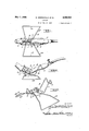
Figure 1 is a top plan view of a stand embodying our invention and showing a torch applied thereto;
Figure 2 is a side elevation of the construction illustrated in Figure 1;
Figure 3 is a perspective view of the stand;
Figure 4 is a view similar to Figure l but showing a slight modification;
Figure 5 is a side elevation of the construction illustrated in Figure 4;
Figure 6 is a perspective View of the stand illustrated in Figures 4 and 5.
Referring now to the drawings, A is the cradle and B is the supporting base of a stand embodying our invention. As shown, the cradle A is formed from a single length of heavy gauge wire and has a substantially fiat base portion I, upwardly inclined portions 2 and 3, respectively, at opposite ends of said base portion, and depending U-shaped end portions 4 and 5, respectively, at the upper ends of said inclined portions. Preferably the inclined portion 2 is shorter than the inclined portion 3 and the depending portion 5 is longer than the depending portion-4. The base B is also formed from a single length of wireand has laterally spaced sides 6 and I and longitudinally curved sub.- stantially triangular-shaped legs 6* and .l Preferably this base crosses and is welded to the base I of the cradle. The ground engaging. portions} 6* and'l respectively of the legs 6 and T arepreferably parallel and form runways for the stand. Portions 8- and 9, respectively, of the base formed by the free ends of'the wire extend upwardly at the base I andare fashioned asshown to -hold' a torch such as X in the cradle A.
In use, the torch X may be easily and quickly placedlinor removed from the cradle A between the'holding portions 8 and 9 and the stand may be -readily secured to or moved over any suitable surface. In this connection it will be noted that the construction of thestand is suchthat the torch'will be prevented from wobbling or snakingwhenthestand is moved, hence may be moved about safely while in the cradle Like-- Wise the construction is such that the flames issuingfrom the torch when lit will be directed away 'from 'theground or flooring, hence the equipment maybe used safely on wood flooring.
In Figures 4 to 6, inclusive, we have illustrated a slight modification wherein inverted substantially U-shaped members 20 and 2| extend upwardly from the cradle A and base B, respectively, and have depending substantially V- shaped portions 22 and 23, respectively, at their upper ends for supporting a soldering iron such as Z. Preferably the U-shaped portion 2| extends slightly above the U-shaped portion 20 and the V-shaped portion 23 is at a higher point that the V-shaped portion 22 so that the soldering iron Z will be supported in a somewhat inclined position with its soldering point 25 just above and adapted to be heated by flames issuing from the mixing chamber 26 of the torch.
What we claim as our invention is:
l. A stand of the class described, comprising an arched base, a cradle for receiving and supporting a blow torch extending across. and secured to said base, and means projecting from the base into the cradle for holding the blow torch against accidental displacement.
2. A stand of the class described, comprising a base, a cradle for receiving and supporting a blow torch extending across and secured to said base, and means for holding the blow torch in the cradle including projections on the base formed to permit substantially vertical movement of the blow torch relative to the base but to prevent endwise or horizontal movement thereof.
3. A stand of the class described, comprising a base, a cradle for receiving and supporting a blow torch extending across and secured to said base, and means for holding the blow torch in the cradle including a pair of cooperating upstanding projections on the base.
4. A stand of the class described, comprising a cradle having portions for receiving and supporting a blow torch, a base for supporting the cradle, and means for supporting a soldering iron above the cradle so that the soldering point thereof will be adjacent and heated by flames issuing from the torch, including means.pro-
jecting upwardly from the cradle and base respectively.
5. A stand of the class described, comprising a cradle, and a supporting base therefor,-the cradle being formed from a single length of wire, and provided at opposite ends thereof with upwardly opening substantially U-shaped portions, and the base being also formed from a single length of wire and having portions thereof extending upwardly into the cradle for holding a blow torch therein.
6. A stand of the class described, comprising a cradle, and a supporting base therefor, the cradle being provided at opposite ends thereof with upwardly opening substantially U- shaped portions, and the base having portions thereof extending upwardly into the cradle for holding a blow torch therein.
7. A stand of the class described, comprising an elongated cradle having upwardly opening substantially U-shaped portions at opposite ends thereof for the reception of a blow torch, and a supporting base for said cradle secured thereto intermediate of its ends and having projections within the cradle serving to hold the blow torch therein.
8. A stand of the class described, comprising an arched elongated base, opposite ends of said base being relatively wide and constituting supporting legs, the intermediate arched portion of said base being relatively narrow, and an elongated cradle extending across and secured to said narrow portion, opposite ends of said cradle being elevated with respect to the narrow portion and formed for the reception of a blow torch.
9. A stand of the class described, comprising a base, an elongated cradle extending across said base and having means for receiving and supporting a hand-operated blow torch, and means for supporting a soldering iron above the cradle so that the point of said iron will be adjacent and heated by flames issuing from said torch, including uprights carried respectively by said base and cradle.
10. A stand of the class described comprising a base formed of wire, a cradle for receiving and supporting a blow torch extending across and secured-to said base, and means for holding the blow torch against accidental displacement from the cradle including portions of the wire projecting into the cradle.
11. A stand of theclass described comprising a base formed of wire, a cradle extending across and secured to said base and having means for receiving and supporting a hand operated blow torch, portions of the wire forming the base projecting into the cradle and cooperating with each other to hold a blow torch in said cradle, and means for supporting a soldering iron above the cradle so that the point of said iron will be adjacent and heated by flames issuing from said torch, including uprights at spaced points of said cradle carried by said cradle and base respectively.
'12. A stand of the class described comprising a base, an elongated cradle extending across and secured to said base, said cradle having means for receiving and supporting a hand operated blow torch, and said base having portions projecting into said cradle for holding a blow torch therein, and means at spaced points longitudinally of said cradle for supporting a soldering iron above the cradle so that the point of the iron will be adjacent and heated by flames issuing from said torch.
EUGENE :GREENFIELD. FED. J. THIBAULT.
Priority Applications (1)
| Application Number | Priority Date | Filing Date | Title |
|---|---|---|---|
| US655820A US2000592A (en) | 1933-02-08 | 1933-02-08 | Support |
Applications Claiming Priority (1)
| Application Number | Priority Date | Filing Date | Title |
|---|---|---|---|
| US655820A US2000592A (en) | 1933-02-08 | 1933-02-08 | Support |
Publications (1)
| Publication Number | Publication Date |
|---|---|
| US2000592A true US2000592A (en) | 1935-05-07 |
Family
ID=24630505
Family Applications (1)
| Application Number | Title | Priority Date | Filing Date |
|---|---|---|---|
| US655820A Expired - Lifetime US2000592A (en) | 1933-02-08 | 1933-02-08 | Support |
Country Status (1)
| Country | Link |
|---|---|
| US (1) | US2000592A (en) |
-
1933
- 1933-02-08 US US655820A patent/US2000592A/en not_active Expired - Lifetime
Similar Documents
| Publication | Publication Date | Title |
|---|---|---|
| US1485852A (en) | Display stand | |
| US1876172A (en) | Display rack | |
| US2316892A (en) | Removable tray rack construction | |
| US2250361A (en) | Portable holder | |
| US20130269674A1 (en) | Fire pit with radiant heat cooker | |
| US3252590A (en) | Apparatus for tilting motor cars | |
| US1960862A (en) | Golf club carrier | |
| US1966751A (en) | Casket rack | |
| US2000592A (en) | Support | |
| US2191693A (en) | Tumbler rack | |
| US1850647A (en) | Method and apparatus for displaying tiles | |
| US2814286A (en) | Device for warming beverages | |
| US2008180A (en) | Display stand | |
| US2511073A (en) | Lift truck | |
| US20120298097A1 (en) | Barbecue Stove | |
| US2206083A (en) | Rack | |
| US2608360A (en) | Combined wheelbarrow and hose reel | |
| US2740679A (en) | Table top with removable leg supports | |
| US2546539A (en) | Vertically adjustable furniture truck | |
| US2664307A (en) | Rack truck for rugs | |
| US1818518A (en) | Rope display stand | |
| US2030594A (en) | Assembly table | |
| JP3199275U (en) | Working apparatus and sled apparatus for the apparatus | |
| CN212531188U (en) | A surface treatment feeding line operating high platform | |
| US2164519A (en) | Scaffolding |