US2000321A - Magazine shoe filler unit - Google Patents
Magazine shoe filler unit Download PDFInfo
- Publication number
- US2000321A US2000321A US694394A US69439433A US2000321A US 2000321 A US2000321 A US 2000321A US 694394 A US694394 A US 694394A US 69439433 A US69439433 A US 69439433A US 2000321 A US2000321 A US 2000321A
- Authority
- US
- United States
- Prior art keywords
- magazine
- units
- heater
- filler
- stack
- Prior art date
- Legal status (The legal status is an assumption and is not a legal conclusion. Google has not performed a legal analysis and makes no representation as to the accuracy of the status listed.)
- Expired - Lifetime
Links
Images

Classifications
-
- A—HUMAN NECESSITIES
- A43—FOOTWEAR
- A43D—MACHINES, TOOLS, EQUIPMENT OR METHODS FOR MANUFACTURING OR REPAIRING FOOTWEAR
- A43D25/00—Devices for gluing shoe parts
- A43D25/14—Devices for filling the shoe bottom
Definitions
- the filler units are usually made of a heat plastic material and it is therefore desirable not only lthat a suitable supply of filler units be made readily accessible to e the shoe filling operator and that the units be delivered to him one by one as required but that the units be heat-conditioned to render them plastic as they are successively delivered to the operator for laying and spreading in the shoe,
- the present invention relates to apparatus for holding or storing a supply of shoe-bottom filler units and. individually delivering them4 to the operator and individually heat-conditioning them preparatory to spreading them in the shoe bottom cavities.
- Such filler units are commonly furnished in an elongated six-sided rhomboidal form and the apparatus vherein shown is especially designed to handle such forms, although the invention is notlimited to any par- The invention is also especially although not exclusively intended for association and use in connection with and as an adjunct or attachment to a shoe filling machine.
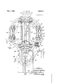
- Fig. 1 is a plan view of apparatus embodying the invention.
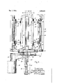
- Fig. 2 is a front elevation of said apparatus
- Fig. 3 is a section on line 3 3 'of 1ig.v2. ⁇
- IB represents a base consisting of a metal plate fastened upon the outer end of a bracket arm I I, which is provided with an apertured hub I2 pivotally mounted upon the end of an arm I3 by whichithe whole apparatus is supported.
- the arm I 3 is fixed to the frame or standard of a shoe bottom filling machine (not shown) so as to support the apparatus incon- 7 l venient association and relation for use in con.-
- the top side of the base I is'iny the main fiat and is formed with anannular groove I4 within which is rotatably mounted a ring I 5 which constitutes a'rotatable annular support carrying four upright magazines unif o'rmlyy spaced apart about 1933, Serial No. 694,394
- the top of the base I0 Within the ring I5 is also formed with va straight da* metrical groove I6 whose opposite ends open-.into the groove I4 as shown in Fig. ⁇ 3.
- the ring I5 is formed upon its outer periphery with four sockets I'I uniformly spaced around the ring and adapted severally, to cooperate with a locking bolt I8 which slides endwise in a radial bearing provided on the base I0.
- Therlocking 10 bolt I 8 is made at its outer end a stem I8' which extends loosely through an aperture provided in a bracket I9 fastened tothe basell
- a coil spring 29 surrounds the stem I8 and bears at one end against a shoulder provided on the bolt I8 and at its opposite end against bracket I9 thus yieldingly urging the bolt I 8toward and against the ring I5.
- Attached to the ibottom of the slide isa depending arm 24 whoselowerend is connected by a link 25 with one of the arms of a hand lever 26 fulcrumed at 21 on a bracket 28iv 35 which is fastened to the under side ofthe heater presently to be described.
- the arm 24 extends downwardly from the slide through a slot 29 provided in the base I0 Vthroughthe middle of groove I6. The free end of the hand with an operating handle 26".
- Each of the four magazines carried on yring I5 is loaded with a stack of ller units 30, thestack being supported mainly on the ring I 5.
- a loaded magazine is at delivery station A (Fig. 1) 4g it is lin such position that the reciprocating feed slide 22v may move back and forth through the bottom of the magazine and stack of ⁇ units and push the lowermost unit in the stack out of the magazine in al direction radialof the ring l5.
- the forward end of the feed slide 22 is beveledr upon its top side soas to insure thatthe'thickness of the end ofthe feed slide will be less than rthel thickness of a filler unit and'will engage and deliver onlyone -unit from the bottom of the stack, 'V
- the feed slide is reciprocated by the hand lever 26 and the movement of the lever and slide in its forward or delivery direction is limited by engagement of the lever 26 with a stop lug 3
- each forward or delivery movement of the feed slide its upper member or plate 22 engages the edge of the loWermost filler unit in .the magazine at the delivery station A and pushesl it forward out of the magazine and on toa heater 33 by which the unit is warmed to .render it plastic and spreadable.
- the unit is then .transferred to the bottom cavity of the shoe for the spreading and filling operation in the filling machine.
- several filler units are usually kept in position upon the heater 33 and eachltime a heated filler unit is .transferred to a shoe the ⁇ leverj26 is operatedto feed another unit from the hopper to the feeder.
- the units are then removed from the heater and used in the order in which they are fed to the heater from the magazine so that the proper heating and conditioning of one VVor more'ller units may go on while a preceding unit is being laid in the shoe.
- 'I'he Y,heater 33 is a shelf-like structure comprising an. iron base plate 34 and a brass or copper top plate 35 fastened together by screws 36 (Fig. l).
- the top surface of the plate 35 is the heating' surface for the filler units and is on the same level as the bottom ofthe magazines and close to the magazine at the delivery station A; hence the surface of the heater forms a slideway surthe heater can be turned on or off and by means bottomof the magazine.
- the base plate 34 is fastened by screws to the top of the pivotallysupported bracket arm I I and has secured to its under side the bracket 28 on which the operating lever 26 is fulcrumed as already described.
- the heater is an annular cavity 3'!
- a small handknife or spatula similar Ato a putty knife is usedby the operator in transferring a ller unit from the heater 33 tothe shoe and may also be used for spreading or partly spreading the material of the filler unit within the stacks of filler units 30 comprises an upright rear wall 4'! provided with a pair of side wings 41' for engaging and guiding the rear edges of the filler pieces 30 in the stack and a pair of legs 48 seated upon and fastened by screws to the ring I5.
- the lower end of the wall 4l, 41' is formed to provide a space or passage betweeen the legs 48 for the passage of a filler unit and the feed slide.
- Each front rail 49 is of angular shape in cross section, as best shown in Fig. 1, so that only the inner edge thereof engages the stack of units.
- Each front railv k49 is made with a pair of hub lugs 50 disposed between a pair of lugs 5I which project from the sides of the rear walls 4?.
- lpintle 52 rextends through aligned holes in lugs and 5I and provides the pivotal connection by which the front rail 49 is hinged to the back wall.
- Each hub lug .59 .of the front rail is provided with an ear 53 formed with a threaded hole within which is mounted an adjustable stop screw 54.
- The'stop screws 54 engage the sides of the back walls 41 tohold the rail against pivotal movement. in one direction on its pintle 52, while the stack of units 30 within the magazine prevents pivotal movement of said rail in the opposite direction.
- the two front rails together with the back walls loosely confine the units of the i stack so that they may move downwardly in the magazine by gravity.
- the stop screws 54 By adjusting the stop screws 54 the orosssectional area of the magazine may be varied to accommodate different sized ller units.
- Apparatus for holding, delivering and heatconditioning shoe-bottom ller units comprising, in combination, a magazine for holding a stack of filler units, a heater adjacent the magazine and means to transfer the filler units individually from the magazine to the heater.
- Apparatus for holding, delivering and heatconditioning shoe-bottom filler units comprising, in combination, a magazine for holding a stack of filler units, a heaterk adjacent the magazine having a top surface ⁇ constructed and adapted to serve as a slideway for the filler units, and'meansI to slide individual units one at a time from the in combination, a magazine for holding a stack of iiller units, a heater adjacent the magazine and a reciprocatcry feed slide to shove the lowermost filler unit of said stack out of the magazine on to the heater.
- Apparatus for holding, delivering and heatconditioning shoe-bottom filler units comprising,
- a magazine for holding a stack of ller units, a heater adjacent the magazine having a top surface constructed and adapted to serve as a slideway for the filler units, the bottom of the magazine constituting substantially a continuation of the slideway surface of the heater and means to slide the lowermost unit of said stack out of the magazine on to the slideway surface of the heater.
- Apparatus for holding, delivering and heatconditioning shoe-bottom ller units comprising, in combination, a magazine for holding a stack of iiller units, a heater adjacent the magazine hav'- ing a top surface constructed and adapted to serve as a slidevvay for the i'lller units, the bottom of the magazine constituting substantially a continuation of the slideWay surface of the heater and a reciprocatory feed slide to shove the lowermost ller unit of said stack out of the magazine on to the heater.
- Apparatus for holding and delivering shoebottom ller units comprising, in combination, a number of magazines, each for holding a stack of ller units, means connecting the magazines together whereby they may be moved in unison to bring them successivelj7 to a delivery station, a heater adjacent the delivery station, and means to deliver the filler units individually to the heater from that one of the several magazines Which is at the delivery station.
- Apparatus for holding and delivering shoebottom iiller units comprising, in combination, a number of magazines, each for holding a stack of filler units, means connecting the magazines together whereby they may be moved in unison to bring them successively to a delivery station, a heater adjacent the delivery station, means for locking the magazines at the delivery station, and means to deliver the iiller units individually to the heater from that one of the several magazines which is at the delivery station.
- Apparatus for holding and delivering shoebottom ller units comprising, in combination, a rotatable support, a number of magazines carried by said support, each magazine adapted to hold a stack of filler units, the support being rotatably adjustable to bring the magazine successively to a delivery station, a heater adjacent the delivery station, and means to deliver the filler units individually to the heater from that one of the several magazines Which is at the delivery station.
- Apparatus for holding and delivering shoebottom ller units comprising, in combination, a rotatable support, a number of magazines carried by said support, each magazine adapted to hold a stack of ller units, the support being rotatably adjustable to bring the magazines successively to a delivery station, a heater adjacent the delivery station, means for locking the support in its adjusted positions, and means to deliver the ller units individually to the heater from that one of the several magazines which is at the delivery station.
- Apparatus for holding and delivering shoebottom ller units comprisng, in combination, an annular support, a number of magazines carried by said annular support, each magazine adapted to hold a stack of filler units, the annular support being rotatably adjustable to bring the magazine successively to a delivery station, a heater adjacent the delivery station, and a reciprocatory feed slide operating from Within the annular support to deliver the filler units individually to the heater from that one of the several magazines which is at the delivery station.
- Apparatus for holding and deliveringshoebottom ller units comprising, in combination, an annular support, a number of magazines carried by said annular support, each magazine adapted to hold a stack of filler ⁇ units, the annular support being rotatably adjustable to bring the magazines successively to a delivery station, a heater adjacent the delivery station, means for locking the support in its adjusted positions, and a reciprocatory feed slide operating from Within the annular support to deliver. the iiller units individually to the .heater fromithat one of the several magazines which is at the delivery station.
- Apparatus for holding, delivering and heatconditioning shoe-bottom filler units comprising, in combination, a rotatable support, a number of magazines carried by said support, each magazine adapted to hold a stack of ller units, the top side of the support constituting the bottom of each magazine, a heater adjacent the rotatable support having a top surface constituting substantially a continuation of the bottom of each magazine when the magazine is in delivery position, the support being rotatably adjustable to bring the magazines successively into delivery position opposite the heater, and a feed slide operable to shove the lovvermost ller unit from that one of the magazines which is in delivery position onto the heater.
- Apparatus as claimed in claim l further characterized in that said magazine comprises an upright rear Wall for engaging and guiding one side of thestack of ller units arranged in the magazine and an upright front Wall for engaging and guiding the other side of the stack of ller units, said Walls being relatively adjustable to- Ward and from each other to accommodate ller units of different sizes.
- Apparatus as claimed in claim 1 further characterized in that ,said magazine comprises an upright rear Wall for engaging and guiding one side of the stack of ller units arranged in the magazine, a pair of upright rails for engaging and guiding the other side of the stack of ller units, said rails being adjustable toward and from the rear wall, and adjustable stops for limiting the movement of said rails away from the rear Wall.
Description
May 7, 1935. c. F. EATON `2,000,321v
MAGAZINE SHOE FILLER UNI-1f File@ 0015.20, 1955, 5 sheets-*sheet 2 May 7,'1935. c. F. EAToNy MAGAZINE SHOE FILLER UNIT 5 sheets-sheet 3 Filed Oct. 20, 1953 Patented May 7, 1935 UNITEDf-STATES PATENT OFFICE 2,000,321 MAGAZINE snor: FILLER UNIT Charles F. Eaton, West Newbury, Mass., assignorV to North American Chemical Company, Cam-F Y bridge, Mass., la corporation of Massachusetts Application October 20,
14 Claims.
For the filling of shoe bottom cavities filler 5 and claimed in the ThomaPatent No. 1,793,340
ticular shape of ller units. 30'
dated February 17, 1931. Such filler units may be laid and spread in the shoe bottom cavity by hand, or by a lling machine of the general character illustrated in the Eaton Patent No. 1,927,279
dated September 19, 1933. The filler units are usually made of a heat plastic material and it is therefore desirable not only lthat a suitable supply of filler units be made readily accessible to e the shoe filling operator and that the units be delivered to him one by one as required but that the units be heat-conditioned to render them plastic as they are successively delivered to the operator for laying and spreading in the shoe,
The present invention relates to apparatus for holding or storing a supply of shoe-bottom filler units and. individually delivering them4 to the operator and individually heat-conditioning them preparatory to spreading them in the shoe bottom cavities. Such filler units are commonly furnished in an elongated six-sided rhomboidal form and the apparatus vherein shown is especially designed to handle such forms, although the invention is notlimited to any par- The invention is also especially although not exclusively intended for association and use in connection with and as an adjunct or attachment to a shoe filling machine.
In the accompanying drawings: v v
Fig. 1 is a plan view of apparatus embodying the invention; y
Fig. 2 is a front elevation of said apparatus; and
Fig. 3 is a section on line 3 3 'of 1ig.v2.`
In the embodiment of the invention herein illustrated IB represents a base consisting of a metal plate fastened upon the outer end of a bracket arm I I, which is provided with an apertured hub I2 pivotally mounted upon the end of an arm I3 by whichithe whole apparatus is supported. The arm I 3 is fixed to the frame or standard of a shoe bottom filling machine (not shown) so as to support the apparatus incon- 7 l venient association and relation for use in con.-
junctionfwith'the filling machine. f p
The top side of the base I is'iny the main fiat and is formed with anannular groove I4 within which is rotatably mounted a ring I 5 which constitutes a'rotatable annular support carrying four upright magazines unif o'rmlyy spaced apart about 1933, Serial No. 694,394
the ring and also uniformly spaced from the center of thering. The top of the base I0 Within the ring I5 is also formed with va straight da* metrical groove I6 whose opposite ends open-.into the groove I4 as shown in Fig.` 3.
The ring I5 is formed upon its outer periphery with four sockets I'I uniformly spaced around the ring and adapted severally, to cooperate with a locking bolt I8 which slides endwise in a radial bearing provided on the base I0. Therlocking 10 bolt I 8 is made at its outer end a stem I8' which extends loosely through an aperture provided in a bracket I9 fastened tothe basell A coil spring 29 surrounds the stem I8 and bears at one end against a shoulder provided on the bolt I8 and at its opposite end against bracket I9 thus yieldingly urging the bolt I 8toward and against the ring I5. When the bolt I8 engages one of the sockets Il the ring I5 'is thereby re-V leasably locked in position and held against accidental rotative displacement. .When in` any one of its locked positions one of the four maga-V zines carried by the ring occupies ,position A (Fig. 1)` at one end of the diametricalgroove I6, which constitutes the delivery station for the magazine.
Within the groove I6 is mounted a slide 2|, 22, the bottom member 2| of the slide moving in the groove I6, and the side margins of the mem' ber 22 of the slide'being confined in and guided 30 by a pair of anged guideways 23 fastened tothe top of the base Il). Attached to the ibottom of the slideisa depending arm 24 whoselowerend is connected by a link 25 with one of the arms of a hand lever 26 fulcrumed at 21 on a bracket 28iv 35 which is fastened to the under side ofthe heater presently to be described. The arm 24 extends downwardly from the slide through a slot 29 provided in the base I0 Vthroughthe middle of groove I6. The free end of the hand with an operating handle 26". n
Each of the four magazines carried on yring I5 is loaded with a stack of ller units 30, thestack being supported mainly on the ring I 5. When a loaded magazine is at delivery station A (Fig. 1) 4g it is lin such position that the reciprocating feed slide 22v may move back and forth through the bottom of the magazine and stack of `units and push the lowermost unit in the stack out of the magazine in al direction radialof the ring l5. The forward end of the feed slide 22 is beveledr upon its top side soas to insure thatthe'thickness of the end ofthe feed slide will be less than rthel thickness of a filler unit and'will engage and deliver onlyone -unit from the bottom of the stack, 'V
thus permitting the handling of units of considerable variation in thickness. The feed slide is reciprocated by the hand lever 26 and the movement of the lever and slide in its forward or delivery direction is limited by engagement of the lever 26 with a stop lug 3| on bracket 28, while the movement of the lever and slide in the opposite direction is limited by engagement with a second stopvlug 32l on bracket 28.
During each forward or delivery movement of the feed slide its upper member or plate 22 engages the edge of the loWermost filler unit in .the magazine at the delivery station A and pushesl it forward out of the magazine and on toa heater 33 by which the unit is warmed to .render it plastic and spreadable. The unit ,is then .transferred to the bottom cavity of the shoe for the spreading and filling operation in the filling machine. In practice several filler units are usually kept in position upon the heater 33 and eachltime a heated filler unit is .transferred to a shoe the` leverj26 is operatedto feed another unit from the hopper to the feeder. The units are then removed from the heater and used in the order in which they are fed to the heater from the magazine so that the proper heating and conditioning of one VVor more'ller units may go on while a preceding unit is being laid in the shoe.
'I'he Y,heater 33 is a shelf-like structure comprising an. iron base plate 34 and a brass or copper top plate 35 fastened together by screws 36 (Fig. l). The top surface of the plate 35 is the heating' surface for the filler units and is on the same level as the bottom ofthe magazines and close to the magazine at the delivery station A; hence the surface of the heater forms a slideway surthe heater can be turned on or off and by means bottomof the magazine.
face which .is substantially a continuation of the The base plate 34 is fastened by screws to the top of the pivotallysupported bracket arm I I and has secured to its under side the bracket 28 on which the operating lever 26 is fulcrumed as already described. Upon the Vtop of the base plate 34vof the heater is an annular cavity 3'! within which is Yplaced an annular electric heatingA unit 38-provided with three binding posts 39, 40 and 4I, the binding posts 39 and 4I being connected with theopposite ends of the usual filment of the heating unit and the binding post 49 being connected with an n intermediate part of said filament.` Conductors 42,1ead from the binding posts of thelheating unit into ajunction box 43 secured to the underside of the` base plate 34 and thence througha flexible conduit '44 to a source of electric current. A switch S vis installed in said line by means of which of which the action of the heater can be regulated so as to operate with greater or less intensity.
A small handknife or spatula similar Ato a putty knife is usedby the operator in transferring a ller unit from the heater 33 tothe shoe and may also be used for spreading or partly spreading the material of the filler unit within the stacks of filler units 30 comprises an upright rear wall 4'! provided with a pair of side wings 41' for engaging and guiding the rear edges of the filler pieces 30 in the stack and a pair of legs 48 seated upon and fastened by screws to the ring I5. The lower end of the wall 4l, 41', is formed to provide a space or passage betweeen the legs 48 for the passage of a filler unit and the feed slide.
Pivoted to the opposite edges of the walls 41 are two vertical front rails 49 for engaging and guiding the front edges of the units in the stack. Each front rail 49 is of angular shape in cross section, as best shown in Fig. 1, so that only the inner edge thereof engages the stack of units. Each front railv k49is made with a pair of hub lugs 50 disposed between a pair of lugs 5I which project from the sides of the rear walls 4?. A
lpintle 52 rextends through aligned holes in lugs and 5I and provides the pivotal connection by which the front rail 49 is hinged to the back wall.
Each hub lug .59 .of the front rail is provided with an ear 53 formed with a threaded hole within which is mounted an adjustable stop screw 54. The'stop screws 54 engage the sides of the back walls 41 tohold the rail against pivotal movement. in one direction on its pintle 52, while the stack of units 30 within the magazine prevents pivotal movement of said rail in the opposite direction. Thus the two front rails together with the back walls loosely confine the units of the i stack so that they may move downwardly in the magazine by gravity. By adjusting the stop screws 54 the orosssectional area of the magazine may be varied to accommodate different sized ller units.
When the supply of Aller units in the magazine which is at delivery station A is exhausted the operator withdraws the locking bolt I8 from its socket I 'I and turns thering I5 until another magazine comes` into position at station A whereupon the locking bolt I8 snaps into another socket I1 and holds the rotatable magazine support in its` newpositlon. 'I'l1us,v a filled magazine may quickly and readily be substituted for an empty one and while the empty magazine is out of working position it may be refilled with a fresh stack of ,filler units. 'I'he tapered end of the locking bolt I8 and the correspondingly tapered sockets I'I serve not only to holdthe rotatable support in adjusted position but to justify and accurately true up its position with relation to the reciprocatingfeed slide.
While I have shown for the purpose of illustration a turret-like or rotatable magazine structure having four magazines it is to be understood that the invention is not limited to any particular number of magazines.`
I claim:
1. Apparatus for holding, delivering and heatconditioning shoe-bottom ller units comprising, in combination, a magazine for holding a stack of filler units, a heater adjacent the magazine and means to transfer the filler units individually from the magazine to the heater.
2. Apparatus for holding, delivering and heatconditioning shoe-bottom filler units comprising, in combination, a magazine for holding a stack of filler units, a heaterk adjacent the magazine having a top surface `constructed and adapted to serve as a slideway for the filler units, and'meansI to slide individual units one at a time from the in combination, a magazine for holding a stack of iiller units, a heater adjacent the magazine and a reciprocatcry feed slide to shove the lowermost filler unit of said stack out of the magazine on to the heater.
4. Apparatus for holding, delivering and heatconditioning shoe-bottom filler units comprising,
in combination, a magazine for holding a stack of ller units, a heater adjacent the magazine having a top surface constructed and adapted to serve as a slideway for the filler units, the bottom of the magazine constituting substantially a continuation of the slideway surface of the heater and means to slide the lowermost unit of said stack out of the magazine on to the slideway surface of the heater.
5. Apparatus for holding, delivering and heatconditioning shoe-bottom ller units comprising, in combination, a magazine for holding a stack of iiller units, a heater adjacent the magazine hav'- ing a top surface constructed and adapted to serve as a slidevvay for the i'lller units, the bottom of the magazine constituting substantially a continuation of the slideWay surface of the heater and a reciprocatory feed slide to shove the lowermost ller unit of said stack out of the magazine on to the heater.
6. Apparatus for holding and delivering shoebottom ller units comprising, in combination, a number of magazines, each for holding a stack of ller units, means connecting the magazines together whereby they may be moved in unison to bring them successivelj7 to a delivery station, a heater adjacent the delivery station, and means to deliver the filler units individually to the heater from that one of the several magazines Which is at the delivery station.
7 Apparatus for holding and delivering shoebottom iiller units comprising, in combination, a number of magazines, each for holding a stack of filler units, means connecting the magazines together whereby they may be moved in unison to bring them successively to a delivery station, a heater adjacent the delivery station, means for locking the magazines at the delivery station, and means to deliver the iiller units individually to the heater from that one of the several magazines which is at the delivery station.
8. Apparatus for holding and delivering shoebottom ller units comprising, in combination, a rotatable support, a number of magazines carried by said support, each magazine adapted to hold a stack of filler units, the support being rotatably adjustable to bring the magazine successively to a delivery station, a heater adjacent the delivery station, and means to deliver the filler units individually to the heater from that one of the several magazines Which is at the delivery station.
9. Apparatus for holding and delivering shoebottom ller units comprising, in combination, a rotatable support, a number of magazines carried by said support, each magazine adapted to hold a stack of ller units, the support being rotatably adjustable to bring the magazines successively to a delivery station, a heater adjacent the delivery station, means for locking the support in its adjusted positions, and means to deliver the ller units individually to the heater from that one of the several magazines which is at the delivery station.
10. Apparatus for holding and delivering shoebottom ller units comprisng, in combination, an annular support, a number of magazines carried by said annular support, each magazine adapted to hold a stack of filler units, the annular support being rotatably adjustable to bring the magazine successively to a delivery station, a heater adjacent the delivery station, and a reciprocatory feed slide operating from Within the annular support to deliver the filler units individually to the heater from that one of the several magazines which is at the delivery station.
11. Apparatus for holding and deliveringshoebottom ller units comprising, in combination, an annular support, a number of magazines carried by said annular support, each magazine adapted to hold a stack of filler` units, the annular support being rotatably adjustable to bring the magazines successively to a delivery station, a heater adjacent the delivery station, means for locking the support in its adjusted positions, and a reciprocatory feed slide operating from Within the annular support to deliver. the iiller units individually to the .heater fromithat one of the several magazines which is at the delivery station.
12. Apparatus for holding, delivering and heatconditioning shoe-bottom filler units comprising, in combination, a rotatable support, a number of magazines carried by said support, each magazine adapted to hold a stack of ller units, the top side of the support constituting the bottom of each magazine, a heater adjacent the rotatable support having a top surface constituting substantially a continuation of the bottom of each magazine when the magazine is in delivery position, the support being rotatably adjustable to bring the magazines successively into delivery position opposite the heater, and a feed slide operable to shove the lovvermost ller unit from that one of the magazines which is in delivery position onto the heater.
13. Apparatus as claimed in claim l further characterized in that said magazine comprises an upright rear Wall for engaging and guiding one side of thestack of ller units arranged in the magazine and an upright front Wall for engaging and guiding the other side of the stack of ller units, said Walls being relatively adjustable to- Ward and from each other to accommodate ller units of different sizes.
14. Apparatus as claimed in claim 1 further characterized in that ,said magazine comprises an upright rear Wall for engaging and guiding one side of the stack of ller units arranged in the magazine, a pair of upright rails for engaging and guiding the other side of the stack of ller units, said rails being adjustable toward and from the rear wall, and adjustable stops for limiting the movement of said rails away from the rear Wall.
CHARLES F. EATON.
Priority Applications (1)
| Application Number | Priority Date | Filing Date | Title |
|---|---|---|---|
| US694394A US2000321A (en) | 1933-10-20 | 1933-10-20 | Magazine shoe filler unit |
Applications Claiming Priority (1)
| Application Number | Priority Date | Filing Date | Title |
|---|---|---|---|
| US694394A US2000321A (en) | 1933-10-20 | 1933-10-20 | Magazine shoe filler unit |
Publications (1)
| Publication Number | Publication Date |
|---|---|
| US2000321A true US2000321A (en) | 1935-05-07 |
Family
ID=24788645
Family Applications (1)
| Application Number | Title | Priority Date | Filing Date |
|---|---|---|---|
| US694394A Expired - Lifetime US2000321A (en) | 1933-10-20 | 1933-10-20 | Magazine shoe filler unit |
Country Status (1)
| Country | Link |
|---|---|
| US (1) | US2000321A (en) |
Cited By (2)
| Publication number | Priority date | Publication date | Assignee | Title |
|---|---|---|---|---|
| CN102982145A (en) * | 2012-11-23 | 2013-03-20 | 北京奇虎科技有限公司 | System for allocating database operating requests |
| US20170157705A1 (en) * | 2014-06-12 | 2017-06-08 | Scanlab Gmbh Optische Technologien | Laser Machining Apparatus Comprising a Parallel Displacement Unit |
-
1933
- 1933-10-20 US US694394A patent/US2000321A/en not_active Expired - Lifetime
Cited By (2)
| Publication number | Priority date | Publication date | Assignee | Title |
|---|---|---|---|---|
| CN102982145A (en) * | 2012-11-23 | 2013-03-20 | 北京奇虎科技有限公司 | System for allocating database operating requests |
| US20170157705A1 (en) * | 2014-06-12 | 2017-06-08 | Scanlab Gmbh Optische Technologien | Laser Machining Apparatus Comprising a Parallel Displacement Unit |
Similar Documents
| Publication | Publication Date | Title |
|---|---|---|
| US2000321A (en) | Magazine shoe filler unit | |
| US2713878A (en) | Forming and cutting machine for radio components | |
| US2172847A (en) | Assembling tool | |
| US2672545A (en) | Shoe bottom heater | |
| US2035971A (en) | Pad for labeling machines | |
| US1339569A (en) | Golf-ball marker | |
| US3547738A (en) | Apparatus for creasing and stiffening fabric and for temporarily bonding fabric work-pieces | |
| US2824356A (en) | Apparatus for mounting filaments | |
| US1722771A (en) | Pencil holder for sharpeners | |
| US2269771A (en) | Carbon holder | |
| US1336777A (en) | Threading-machine | |
| US1287669A (en) | Apparatus for securing binding-posts to electrodes. | |
| US2514404A (en) | Broad flexible nozzle for sole cementing | |
| US2053946A (en) | Apparatus for feeding wires | |
| US1731736A (en) | Machine for treeing boots and shoes | |
| US1944882A (en) | Sole laying machine | |
| US1694955A (en) | Marking machine | |
| US2091176A (en) | Strap and buckle assembling apparatus | |
| US3095155A (en) | Illuminating arrangement | |
| US3056149A (en) | Machines for attaching flap portions of loose outsoles to the breasts of loose louisheels | |
| US1980946A (en) | Shoe bottom filling apparatus | |
| US2437431A (en) | Inking and edge setting machine | |
| US2940419A (en) | Article feeding and coating device | |
| US2233094A (en) | Classifying and sorting device | |
| US2288693A (en) | Welding apparatus |