US1999729A - Apparatus for producing graduated involuntary muscular contractions - Google Patents
Apparatus for producing graduated involuntary muscular contractions Download PDFInfo
- Publication number
- US1999729A US1999729A US70266633A US1999729A US 1999729 A US1999729 A US 1999729A US 70266633 A US70266633 A US 70266633A US 1999729 A US1999729 A US 1999729A
- Authority
- US
- United States
- Prior art keywords
- circuit
- current
- potential
- conductor
- grid
- Prior art date
- Legal status (The legal status is an assumption and is not a legal conclusion. Google has not performed a legal analysis and makes no representation as to the accuracy of the status listed.)
- Expired - Lifetime
Links
- 230000004118 muscle contraction Effects 0.000 title description 22
- 238000004804 winding Methods 0.000 description 46
- 239000004020 conductor Substances 0.000 description 38
- 230000015556 catabolic process Effects 0.000 description 26
- 230000001105 regulatory effect Effects 0.000 description 7
- 230000000737 periodic effect Effects 0.000 description 6
- 230000035939 shock Effects 0.000 description 5
- 230000008602 contraction Effects 0.000 description 3
- 238000010438 heat treatment Methods 0.000 description 3
- 230000003387 muscular Effects 0.000 description 3
- 210000000653 nervous system Anatomy 0.000 description 3
- 230000001225 therapeutic effect Effects 0.000 description 3
- 230000009286 beneficial effect Effects 0.000 description 2
- 230000001276 controlling effect Effects 0.000 description 2
- 230000000694 effects Effects 0.000 description 2
- QPLDLSVMHZLSFG-UHFFFAOYSA-N Copper oxide Chemical compound [Cu]=O QPLDLSVMHZLSFG-UHFFFAOYSA-N 0.000 description 1
- 239000005751 Copper oxide Substances 0.000 description 1
- 238000013459 approach Methods 0.000 description 1
- 230000000903 blocking effect Effects 0.000 description 1
- 229910000431 copper oxide Inorganic materials 0.000 description 1
- 125000004122 cyclic group Chemical group 0.000 description 1
- 238000006073 displacement reaction Methods 0.000 description 1
- 230000007794 irritation Effects 0.000 description 1
- QSHDDOUJBYECFT-UHFFFAOYSA-N mercury Chemical compound [Hg] QSHDDOUJBYECFT-UHFFFAOYSA-N 0.000 description 1
- 238000012986 modification Methods 0.000 description 1
- 230000004048 modification Effects 0.000 description 1
- 210000003205 muscle Anatomy 0.000 description 1
- 239000002674 ointment Substances 0.000 description 1
- 230000002747 voluntary effect Effects 0.000 description 1
Images
Classifications
-
- A—HUMAN NECESSITIES
- A61—MEDICAL OR VETERINARY SCIENCE; HYGIENE
- A61N—ELECTROTHERAPY; MAGNETOTHERAPY; RADIATION THERAPY; ULTRASOUND THERAPY
- A61N1/00—Electrotherapy; Circuits therefor
- A61N1/18—Applying electric currents by contact electrodes
- A61N1/32—Applying electric currents by contact electrodes alternating or intermittent currents
- A61N1/36—Applying electric currents by contact electrodes alternating or intermittent currents for stimulation
- A61N1/36003—Applying electric currents by contact electrodes alternating or intermittent currents for stimulation of motor muscles, e.g. for walking assistance
-
- A—HUMAN NECESSITIES
- A61—MEDICAL OR VETERINARY SCIENCE; HYGIENE
- A61N—ELECTROTHERAPY; MAGNETOTHERAPY; RADIATION THERAPY; ULTRASOUND THERAPY
- A61N1/00—Electrotherapy; Circuits therefor
- A61N1/18—Applying electric currents by contact electrodes
- A61N1/32—Applying electric currents by contact electrodes alternating or intermittent currents
- A61N1/36—Applying electric currents by contact electrodes alternating or intermittent currents for stimulation
- A61N1/36014—External stimulators, e.g. with patch electrodes
- A61N1/3603—Control systems
- A61N1/36034—Control systems specified by the stimulation parameters
Definitions
- My invention relates to electro-therapeutical apparatus and more particularly to such a device for producing graduated involuntary muscular contractions in patients.
- Another object of my invention is the provision of an apparatus for producing graduated involuntary muscular contractions wherein the current impulses to which a patient is subjected are of such kind and duration that involuntary muscular contractions are induced without strain or shock to the patient.
- a further object of my present invention is the provision of an electro-therapeutical apparatus contractions wherein the patient is subjected to electrical current impulses of beneficial wave form with an absence of an electrical shock to the nervous system.
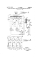
- FIG. 1 is a diagrammatical illustration of the electrical circuit and connections constructed in accordance with my invention.
- FIG. 1 a transformer 5 adapted to have its primary winding 6 connected to the usual al-. ternating current source of domestic potential Ll, L2 by manipulation of a suitable switch I.
- a three electrode discharge device such as a grid glow tube 8
- variable resistance I! to the other plate of the condenser Ill
- conductor I3 extends from a point intermediate the condenser Ill and variable resistance l2 through a fixed resistance H to the grid or control elecfixed resistance 20 to the grid or control electrode of the glow tube It.
- a low voltage winding 22 upon the core of transformer 5 supplies heating current to the winding is connected by a-conductor 26 to one side of the source of commercial supply L2 and I I n from a unction of the for producing raduated involuntary muscular a conductor 2 exte as j conductor 20 to the midpoints of both secondary windings 9 and a, respectively.
- the remaining end of the primary winding 25 is connected by means of a conductor 28 and a fixed resistance 29 to the anode of plate of glow discharge tube 8, 9
- a second primary winding 34 is also wound upon the core of the transformer 24 and has one of its ends connected to a junction of the conductor 30 and thus is connected to the supply conductor LI upon closure of the switch 32.
- the remaining end of this primary 34 is connected by means of a conductor 35 and fixed resistance 36 to the anode or plate of glow discharge tube l6, while its cathode is connected to the remaining supply conductor L2 through the conductor 21 which.extends from the midpoint of the heating windirg 23 and secondary winding l5 to the conductor 26.
- a double pole switch 31 is provided which upon operation is arranged to simultaneously shunt out a portion of the respective resistances 29 and 38 as hereinafter more fully explained.
- the switch 32 is then closed after the cathodes of the tubes 8 and I6 have become heated and, still assuming that the conductors LI and L2 are positive and negative, respectively, a positive potential will be impressed upon the plate of discharge device IS in the following manner: from conductor Ll, through conductor 33, switch 32, conductor 30, to the primary winding 34 of transformer 24, and thence through conductor 35 and resistance 38 to the plate of tube l6.
- the cathode i 6 is impressed with a negative potential from the supply conductor L2 through conductors 28 and 21.
- the tube It ceases to permit current flow therethrough while a potential will be impressed upon the cathode and plate of glow tube 8.
- the cathode of tube I6 is impressed with'a positive polarity through the conductors 26 and 21 which precludes the flow of current therethrough during this half wave.
- the cathode of tube 8 is impressed with a negative plarity through conductor 38, switch 82, and conductor 30.
- the tube 8 reaches its critical breakdown voltage and abruptly breaks down which causes an impulse of current to flow therethrough and through the primary winding 25 in the same manner as previously described relative to the tube l6.
- This current in the primary winding 25 is as shown by the full line curve I8, in Fig. 2. Again the current induced in the secondary winding ,38 will be as shown by the curve I38 during justable arm 39, which is operative to select various points or taps of the secondary winding 38, together with the switch 31 for shunting out of the cathode-plate circuits of glow discharge tubes 8 and IS a portion of the resistances 29 and 36, respectively, thus regulates the strength of the output current supplied to the patient circuit.
- glow discharge tubes 8 and I6 difier from the usual three element vacuum tube in that although having the same electrodes, namely, an anode, thermionic cathode and grid, a mercury vapor at a substantial pressure is present in the tube.
- This type of tube permits the passage of large currents with very little potential drop across the tube and is very critical ,in its operation.
- a suflicient negative potential impressed upon the grid enables the starting potential 0! the oathode-plate circuit to be relatively high and alter the critical breakdown voltage of the grid isv reached attendant discharge between cathode and plate occurs and the grid is unefiective until after interruption or the cathode plate circuit which occurs at each reversal of the alternating current wave as hereinbefore noted.
- the .dotted lines CPIG and CP8 immediately below the upper abscissa line which intersects the respective grid curves VG8 and VGI8 indicates the critical breakdown point of each tube. Due to the particular characteristics of this type of tube the critical breakdown point may be so varied that breakdown will occur when the grid is impressed with either a positive or negative potential. By varying the respective resistances l2 and I8 the phase of the respective grid potentials may be changed so that the breakdown point can be moved along the dotted lines CPIG and CP8 and thus moved above the abscissa line to a positive or in an opposite direction to a higher negative potential.
- each of said discharge devices having the potential thereof out of phase with respect to the potential or the respective circuit in which said discharge device is included, and periodically operable at preselected intervals of each half wave of the alternating current cycle to cause current, flow alternately in each of said circuits, and an output circuit connected to the secondary winding of said transformer adapted to beconnected to a patient and error-- gizable upon the alternate flow of current in both of said circuits to produce graduated involuntary muscular contractions.
- an electro-therapeutical apparatus for producing graduated involutary muscular contractions, the combination with an alternating with respect to the potential of said circuit and periodically operable at preselected intervals during one half wave of the alternating current cycle to cause breakdown of said discharge device and current flow in said circuit, a second circuit energizable by said alternating current source including a second primary winding of said transformer and a second discharge device having a critical breakdown characteristic, said device comprising an anode and a cathode connected to said last mentioned circuit and a control grid, a source of potential connected to the control grid of said last mentioned discharge device having the potential thereof out of phase with respect to the potential of said last mentioned circuit and periodically operable at preselected intervals during the remaining half wave of the alternating current cycle to cause breakdown of said last mentioned discharge device with attendant flow of current in said last mentioned circuit, and an output circuit connected to the secondary winding of said transformer adapted to be connected to a patient and alternately energizable upon current flow in each of said circuits to produce graduated involunta
- an electro-therapeutical apparatus for producing graduated involuntary muscular contractions
- an electro-therapeutical apparatus for producing graduated involuntary muscular contractions, the combination with an alternating current supply source, of a circuit energizable by said source including the primary winding of a transformer and a discharge device having a critical breakdown characteristic, said device comprising an anode and a cathode connected to said circuit and a control grid, a.
- source of electrical potential connected to the control grid of said device including means for varying the phase relation thereof with respect to the potential impressed upon said circuit to cause periodic breakdown of said discharge device at preselected points in the potential wave of said circuit and an abrupt fiow of current through said circuit, means included in said circuit for regulating the current flowing through said circuit upon breakdown of said discharge device, and an output circuit adapted to be connected to a patient for producing graduated involuntary muscular contractions including the secondary winding of said transformer and means for regulating the potential impressed upon a patient,,and energizable upon the abrupt flow of current in said first mentioned circuit.
- an electro-therapeutioal apparatus for producing graduated involuntary muscular contractions
- the combination with an alternating current supply source of a plurality of circuits energizable by said source each including a primary winding of a transformer and a discharge device having a critical breakdown characteristic, said discharge device in each circuit comprising an anode and a cathode connected to its respective circuit and a control grid, a separate source of potential connected to the control grid of each of said discharge devices including means for varying the phase relation thereof with respect to the potential impressed upon the cir-- cuit in which said discharge device is included to cause periodic breakdown of each of said discharge devices at preselected points in the potential wave of each of said circuits and an abrupt alternate flow of current through each of said circuits during the entire alternating cur rent cycle, means included in each of said circuits and simultaneously operable to regulate the current flowing through each respective circuit upon breakdown of each of said discharge devices, and an output circuit adapted to be connected to a patient for producing graduated involuntary muscular contractions including the secondary winding of
- an electro-therapeutical apparatus for producing graduated muscular contractions
- an electro-therapeutical apparatus for producing graduated involuntary muscular contractions
- a circuit energizable by said source including the primary winding of a transformer and a discharge device having a critical breakdown characteristic
- said device comprising an anode and a cathode connected to said circuit and a control grid
- a source of electrical potential connected to the control grid of said device including means for varying the phase relation thereof with respect to the potential impressed upon said circuit to cause periodic breakdown of said discharge device at preselected points in the potential wave of said circuit and an abrupt flow of current through said circuit
- an output circuit including the secondary winding of said transformer and patient electrodes, and energizable upon the abrupt flow of current in said first mentioned circuit to cause graduated involuntary muscular contraction to a patient when connected to said electrodes, and means included in said output circuit to cause current of one sine only to flow therethrough.
- an electro-therapeutical' apparatus for producing graduated involuntary muscular contractions the combination with an alternating current supply source, of a circuit energizable by said source including the primary winding of a transformer and a discharge device having a critical breakdown characteristic, said device comprising an anode and a cathode connected to said circuit and a control grid, a source of electrical potential connected to the control grid of said device including means for varying the phase relation thereof with respect to the potential impressed upon said circuit to cause periodic breakdown of said discharge device at preselected points in the potential wave of said circuit and an abrupt flow of current through said circuit, means included in said circuit for regulating the current flowing through said circuit upon breakdown of said discharge device, an output circuit adapted to be connected to a patient for producing graduated involuntary muscular contractions including the secondary winding of said transformer, means for regulating the potential impressed upon a patient and energizable upon the abrupt flow of current in said first mentioned circuit, and means included in said output circuit to cause current of'one sine only to fiow therethrough
Landscapes
- Health & Medical Sciences (AREA)
- Life Sciences & Earth Sciences (AREA)
- General Health & Medical Sciences (AREA)
- Engineering & Computer Science (AREA)
- Biomedical Technology (AREA)
- Nuclear Medicine, Radiotherapy & Molecular Imaging (AREA)
- Radiology & Medical Imaging (AREA)
- Animal Behavior & Ethology (AREA)
- Public Health (AREA)
- Veterinary Medicine (AREA)
- Heart & Thoracic Surgery (AREA)
- Biophysics (AREA)
- Physical Education & Sports Medicine (AREA)
- Electrotherapy Devices (AREA)
Description
p l 1935- i J. s. KINNEY 7 1,999,729
APPARATUS FOR PRODUCING GRADUATED INVOLUNTARY MUSCULAR CONTRACTIONS Filed Dec. 16, 1933 INVENTOR J 5. ff/ V/VEY ATTORNEY Patented Apr. so, 1935 APPARATUS FOR PRODUCING GRADUATED INVOLUNT ARY MUSCULAR CONTRAC- TIONS J. Stanley Kinney, Wilkinsburg, Pa... assignor, by mesne assignments, to Westinghouse X-Bay Company, Inc., a corporation of Delaware Application December 16, 1933, Serial No. 102,666v
8 Claims. -((:L 174-177) My invention relates to electro-therapeutical apparatus and more particularly to such a device for producing graduated involuntary muscular contractions in patients.
Thebeneficial results of therapeutic treatment of this character has longbeen recognized by the medical profession. In the prior art, however, devices for producing such effects have not been very eflicient nor accepted with much enthusiasm by physicians or patients. because the beneficial results have been more than offset by the discomfort to the patient during the actual administration of a treatment. tors must not only be given consideration in the designing of apparatus for the giving of this type of treatment, but some compensation must be made to overcome the factors which contributetothe irritation experienced by a patient. It is essential, for example, that the current impulses be of such kind and duration that an involuntary contraction of the muscles be produced simulating the natural voluntary contraction without strain or undue shock which so readily producesfatigue. Moreover, the effect of the current applied must not be of the usual form which produces the well known electrical shock that is harmful to the nervous system.
It is accordingly an object of my present invention to produce a therapeutical apparatus for producing graduated involuntary muscular contractions which afiects eillcient therapeutical results and wherein a patient is not subjected to discomfort during the administration of treatment.
Another object of my invention is the provision of an apparatus for producing graduated involuntary muscular contractions wherein the current impulses to which a patient is subjected are of such kind and duration that involuntary muscular contractions are induced without strain or shock to the patient.
A further object of my present invention is the provision of an electro-therapeutical apparatus contractions wherein the patient is subjected to electrical current impulses of beneficial wave form with an absence of an electrical shock to the nervous system.
Still furtherobjects of my invention will become apparent to those skilled in the art to which it a'ppert-ains .by reference to the accompanying drawing wherein:
Figure 1 is a diagrammatical illustration of the electrical circuit and connections constructed in accordance with my invention, and
Several predominating fac- Fig. 2 is a graphic illustration of the wave forms of the electrical energy supplied by my system. Referring now to the drawing in detail I have shown in Fig. 1 a transformer 5 adapted to have its primary winding 6 connected to the usual al-. ternating current source of domestic potential Ll, L2 by manipulation of a suitable switch I. For the purpose of controlling the operation of a three electrode discharge device, such as a grid glow tube 8, as hereinafter more fully explained, the
transformer 5 is provided with a secondary winding 9 of approximately two to one ratio having one of its ends connected to one plate of a condenser Ill.
The remaining end of this secondary winding is connected through a variable resistance I! to the other plate of the condenser Ill, and a conductor I3 extends from a point intermediate the condenser Ill and variable resistance l2 through a fixed resistance H to the grid or control elecfixed resistance 20 to the grid or control electrode of the glow tube It.
A low voltage winding 22 upon the core of transformer 5 supplies heating current to the winding is connected by a-conductor 26 to one side of the source of commercial supply L2 and I I n from a unction of the for producing raduated involuntary muscular a conductor 2 exte as j conductor 20 to the midpoints of both secondary windings 9 and a, respectively. The remaining end of the primary winding 25 is connected by means of a conductor 28 and a fixed resistance 29 to the anode of plate of glow discharge tube 8, 9
ing from the-supply conductor Ll to the midpoint of secondary winding I.
A second primary winding 34 is also wound upon the core of the transformer 24 and has one of its ends connected to a junction of the conductor 30 and thus is connected to the supply conductor LI upon closure of the switch 32. The remaining end of this primary 34 is connected by means of a conductor 35 and fixed resistance 36 to the anode or plate of glow discharge tube l6, while its cathode is connected to the remaining supply conductor L2 through the conductor 21 which.extends from the midpoint of the heating windirg 23 and secondary winding l5 to the conductor 26. A double pole switch 31 is provided which upon operation is arranged to simultaneously shunt out a portion of the respective resistances 29 and 38 as hereinafter more fully explained.
The step-up transformer 24 is provided with a secondary winding 38 which comprises an output or patient circuit and is provided with a series of taps to enable the selection of a varying predetermined voltage in the patient circuit. An adjustable arm 39 is connected by means of a conductor 40 to one of the patient electrodes 42 and a rectifying device 43, such as a copper oxide rectifier commercially known as a fRectox, is interposed in the conductor 40 to allow current of one sign only to flow therethrough. The remaining end of the secondary winding 38'is connected by a conductor 44 through a.- potentiometer 45, which is also connected to conductor 40, and a milliampere meter 46 to the other patient electrode 4?.
In the operation of my system at a given in stant the supply conductor Ll will be impressed with a positive potential while at the same instant the conductor L2 will be negative. Upon closure of the switch 1 current will be induced in the secondary windings 9, 22, i5 and 23 which will supply heating current to the cathodes of the respective glow discharge tubes 8 and I6 and energize the circuits associated with the secondary windings 9 and IS.
The switch 32 being at this time in its normal or open position will prohibit current flow in the cathode-plate circuit of both glow discharge tubes 8 and i6. However, the windings 9 and I5 are at the instant of closure of switch 1 induced with a current and also impressed with a potential at their midpoints through the respective conductors 26, 21 and 33 with the polarity of this potential being the same instantaneous polarity of the respective supply conductors. These windings 9 and I5 accordingly will charge the respective condensers I0 and I! as well as impress either a negative or positive potential upon the grids of the tubes 8 and I6, through conductor l3 and resistance l4, and conductor l9 and resistance 28, respectively.
The switch 32 is then closed after the cathodes of the tubes 8 and I6 have become heated and, still assuming that the conductors LI and L2 are positive and negative, respectively, a positive potential will be impressed upon the plate of discharge device IS in the following manner: from conductor Ll, through conductor 33, switch 32, conductor 30, to the primary winding 34 of transformer 24, and thence through conductor 35 and resistance 38 to the plate of tube l6. At the same instant the cathode i 6 is impressed with a negative potential from the supply conductor L2 through conductors 28 and 21. However, no
the negative supply conductor L2.
the blocking action 01' the grid which is now impressed with a negative potential.
The action of the winding I5 together with its associated circuit for' impressing a negative potential upon the grid of the tube l 6 is naturally a cyclic one as well as the polarity of the potential impressed upon the cathode and plate there'- of as just assumed. This grid circuit, however,
time period the instant of closure of the switch 32 and with the polarity of the supply conductors and that impressed upon the cathode and grid of tube l3 being as above assumed, the voltage wave form of the cathode-plate circuit will/be as indicated by the dotted curve EPI6 which is approaching its peak. At the same instant the grid potential wave form VGIG, which is out of phase with the cathode-plate voltage, has crossed its zero point and after a brief interval of time becomes slightly higher negative. When this grid potential reaches its critical breakdown voltage, the resistance of glow discharge tube is broken down and it functions as a switch thus closing and causing an abrupt impulse of current to flow through the primary winding 34 of transformer 24, having a waveform as shown by the dotted curve H6 in the lower portion of Fig. 2 wherein the ordinate represents current while the abscissa still indicates time.
This in turn induces a current in the secondary winding 38 having a wave form as shown at I38 at each instant during which the current in the primary 34 is as indicated at IIS. This current accordingly is supplied to the patient electrodes 42 and 41 with the magnitude of the voltage being regulated by the potentiometer 45 and as the current wave reverses due to the inherent action of the alternating current cycle the remaining or negative half wave is suppressed by the rectifying action of the rectox 43.
It must be appreciated that the action of the voltage and current as just described relative to the circuits associated with the glow discharge tube 16 and primary winding 34 is but a momentary one which lasts only during one half wave of the alternating current cycle. Also during this same half cycle the potential impressed upon the grid of glow discharge tubeil will not only be positive, as shown by the full line curve VGB in Fig. 2, but the cathode-plate voltage of the tube 8 will be in its negative half wave with the tube preventing passage of any current therethrough even in the absence of a grid. For example, upon initial closure of the switch 32 with supply conductor Ll being positive it follows that a positive potential is impressed upon the cathode of tube 8 and a negative polarity upon the end of primary winding 25 which is connected to Accordingly no current would pass through tube 8 due to the well known valve action of thermionic valve tubes even if the grid was not provided.
When, however, the alternating current cycle reverses, thus making the polarity of the supply conductor Ll negative and that of supply canductor L2 positive, the tube It ceases to permit current flow therethrough while a potential will be impressed upon the cathode and plate of glow tube 8. Assuming the cycle to have reversed the cathode of tube I6 is impressed with'a positive polarity through the conductors 26 and 21 which precludes the flow of current therethrough during this half wave. On the other hand the cathode of tube 8 is impressed with a negative plarity through conductor 38, switch 82, and conductor 30. At this same instant a positive polarity is impressed upon the plate of tube 8 through conductor 26, primary winding 25, conductor 28 and resistance 29 but although a potential is now impressed upon the cathode and plate of the tube 8, as shown by the full line curve EP8 in Fig. 2, no current will as yet flow therethrough. This is because the potential impressed upon the grid of the tube 8 by the phase shifting circuit associated with the secondary winding 8, as shown by the full line curve VG8 in Fig. 2, is still positive. As the cathode-plate voltage approaches its maximum the grid potential recedes and when it becomes slightly negative, which is at the instant when the cathode-plate voltage is substantially at the peak 01' its wave, the tube 8 reaches its critical breakdown voltage and abruptly breaks down which causes an impulse of current to flow therethrough and through the primary winding 25 in the same manner as previously described relative to the tube l6.
This current in the primary winding 25 is as shown by the full line curve I8, in Fig. 2. Again the current induced in the secondary winding ,38 will be as shown by the curve I38 during justable arm 39, which is operative to select various points or taps of the secondary winding 38, together with the switch 31 for shunting out of the cathode-plate circuits of glow discharge tubes 8 and IS a portion of the resistances 29 and 36, respectively, thus regulates the strength of the output current supplied to the patient circuit. It should likewise be further noted that the glow discharge tubes 8 and I6 difier from the usual three element vacuum tube inthat although having the same electrodes, namely, an anode, thermionic cathode and grid, a mercury vapor at a substantial pressure is present in the tube.
This type of tube permits the passage of large currents with very little potential drop across the tube and is very critical ,in its operation. A suflicient negative potential impressed upon the grid enables the starting potential 0! the oathode-plate circuit to be relatively high and alter the critical breakdown voltage of the grid isv reached attendant discharge between cathode and plate occurs and the grid is unefiective until after interruption or the cathode plate circuit which occurs at each reversal of the alternating current wave as hereinbefore noted.
Accordingly the .dotted lines CPIG and CP8 immediately below the upper abscissa line which intersects the respective grid curves VG8 and VGI8 indicates the critical breakdown point of each tube. Due to the particular characteristics of this type of tube the critical breakdown point may be so varied that breakdown will occur when the grid is impressed with either a positive or negative potential. By varying the respective resistances l2 and I8 the phase of the respective grid potentials may be changed so that the breakdown point can be moved along the dotted lines CPIG and CP8 and thus moved above the abscissa line to a positive or in an opposite direction to a higher negative potential.
It thus becomes obvious to those skilled in the art thatI have provided'an electro-therapeutical apparatus for producing involuntary muscular contractions wherein a current is supplied to a patient during each half wave of the alternating current cycle or every of a second. Moreover, the magnitude of the current and voltage is controllable to an exceptionally fine degree so that the current supplied to the patient produces no discomforting eilects' nor causes shocks to the nervous system.
Although I have shown and described one specific embodiment of my invention I do not desire to be limited thereto as other modifications of the same may be made without departing from the spirit and scope of the appended claims. What is claimed: 1. In an electro-therapeutical apparatus for producing graduated involuntary muscular contractions, the combination with an alternating current supply source, of a plurality of circuits connected to said source each including a primary winding of a transformer and a discharge device, said discharge device in each circuit including an anode and a cathode connected to its respective circuit and a control grid, a source of potential for the grid oi. each of said discharge devices having the potential thereof out of phase with respect to the potential or the respective circuit in which said discharge device is included, and periodically operable at preselected intervals of each half wave of the alternating current cycle to cause current, flow alternately in each of said circuits, and an output circuit connected to the secondary winding of said transformer adapted to beconnected to a patient and error-- gizable upon the alternate flow of current in both of said circuits to produce graduated involuntary muscular contractions.
2. In an electro-therapeutical apparatus for producing graduated involutary muscular contractions, the combination with an alternating with respect to the potential of said circuit and periodically operable at preselected intervals during one half wave of the alternating current cycle to cause breakdown of said discharge device and current flow in said circuit, a second circuit energizable by said alternating current source including a second primary winding of said transformer and a second discharge device having a critical breakdown characteristic, said device comprising an anode and a cathode connected to said last mentioned circuit and a control grid, a source of potential connected to the control grid of said last mentioned discharge device having the potential thereof out of phase with respect to the potential of said last mentioned circuit and periodically operable at preselected intervals during the remaining half wave of the alternating current cycle to cause breakdown of said last mentioned discharge device with attendant flow of current in said last mentioned circuit, and an output circuit connected to the secondary winding of said transformer adapted to be connected to a patient and alternately energizable upon current flow in each of said circuits to produce graduated involuntary muscular contractions.
3. In an electro-therapeutical apparatus for producing graduated involuntary muscular contractions, the combination with an alternating current supply source, of a circuit energizable by said source including the primary winding of a transformer and a discharge device having a critical breakdown characteristic, said device comprising an anode and a cathode connecte to said circuit and a control grid, a source of electrical potential connected to the control grid of said device including means for varying the phase relation thereof with respect to the potential impressed upon said circuit to cause periodic breakdown of said discharge device at preselected points in the potential wave of said circuit and an abrupt flow of current through said circuit, and an output circuit including the secondary winding of said transformer and patient electrodes, and energizable upon the abrupt flow of current in said first mentioned circuit to cause graduated involuntary muscular contraction to a patient when connected to said electrodes.
4. In an electro-therapeutical apparatus for producing graduated involuntary muscular contractions, the combination with an alternating current supply source, of a circuit energizable by said source including the primary winding of a transformer and a discharge device having a critical breakdown characteristic, said device comprising an anode and a cathode connected to said circuit and a control grid, a. source of electrical potential connected to the control grid of said device including means for varying the phase relation thereof with respect to the potential impressed upon said circuit to cause periodic breakdown of said discharge device at preselected points in the potential wave of said circuit and an abrupt fiow of current through said circuit, means included in said circuit for regulating the current flowing through said circuit upon breakdown of said discharge device, and an output circuit adapted to be connected to a patient for producing graduated involuntary muscular contractions including the secondary winding of said transformer and means for regulating the potential impressed upon a patient,,and energizable upon the abrupt flow of current in said first mentioned circuit.
5. In an electro-therapeutioal apparatus for producing graduated involuntary muscular contractions, the combination with an alternating current supply source, of a plurality of circuits energizable by said source each including a primary winding of a transformer and a discharge device having a critical breakdown characteristic, said discharge device in each circuit comprising an anode and a cathode connected to its respective circuit and a control grid, a separate source of potential connected to the control grid of each of said discharge devices including means for varying the phase relation thereof with respect to the potential impressed upon the cir-- cuit in which said discharge device is included to cause periodic breakdown of each of said discharge devices at preselected points in the potential wave of each of said circuits and an abrupt alternate flow of current through each of said circuits during the entire alternating cur rent cycle, means included in each of said circuits and simultaneously operable to regulate the current flowing through each respective circuit upon breakdown of each of said discharge devices, and an output circuit adapted to be connected to a patient for producing graduated involuntary muscular contractions including the secondary winding of said transformer and means for regulating the potential impressed upon a patient and energizable upon the flow of current in each of said first mentioned circuits.
6. In an electro-therapeutical apparatus for producing graduated muscular contractions, the combination with an alternating current supply source, of a circuit energizable by said source including the primary winding of a transformer and a discharge device having a critical breakdown characteristic, said device comprising an anode and a cathode connected to said circuit and a control grid, means for impressing a potential upon the control grid of said device having the potential thereof out of phase with respect to the potential impressed upon said circuit to cause periodic breakdown of said discharge device at preselected points in the potential wave of said circuit and abrupt flow of current therethrough comprising a secondary winding energized by said alternating current source, a condenser connected to said secondary winding for accumulating an electrical charge, a variable resistance connected in electrical series relationship with said secondary winding and said condenser for varying the rate of accumulating of a charge in said condenser and to predetermine the phase displacement of said grid potential relativeto the potential of said circuit, and connections from said, condenser to the control grid of said device; a resistance in said first mentioned circuit for limiting the current flowing therethrough upon breakdown of said discharge device, control means operable to exclude a portion of said resistance from said first mentioned circuit to increase the current flowing through said circuit, and an output circuit inductively coupled with said first mentioned circuit adapted to be connected to a patient for producing graduated involuntary muscular contractions including controlling means for regulating the potential supplied to said patient, and energizable upon the abrupt flow of current in said first mentioned circuit.
7. In an electro-therapeutical apparatus for producing graduated involuntary muscular contractions, the combination with an alternating current supply source, of a circuit energizable by said source including the primary winding of a transformer and a discharge device having a critical breakdown characteristic, said device comprising an anode and a cathode connected to said circuit and a control grid, a source of electrical potential connected to the control grid of said device including means for varying the phase relation thereof with respect to the potential impressed upon said circuit to cause periodic breakdown of said discharge device at preselected points in the potential wave of said circuit and an abrupt flow of current through said circuit, an output circuit including the secondary winding of said transformer and patient electrodes, and energizable upon the abrupt flow of current in said first mentioned circuit to cause graduated involuntary muscular contraction to a patient when connected to said electrodes, and means included in said output circuit to cause current of one sine only to flow therethrough.
8. In an electro-therapeutical' apparatus for producing graduated involuntary muscular contractions, the combination with an alternating current supply source, of a circuit energizable by said source including the primary winding of a transformer and a discharge device having a critical breakdown characteristic, said device comprising an anode and a cathode connected to said circuit and a control grid, a source of electrical potential connected to the control grid of said device including means for varying the phase relation thereof with respect to the potential impressed upon said circuit to cause periodic breakdown of said discharge device at preselected points in the potential wave of said circuit and an abrupt flow of current through said circuit, means included in said circuit for regulating the current flowing through said circuit upon breakdown of said discharge device, an output circuit adapted to be connected to a patient for producing graduated involuntary muscular contractions including the secondary winding of said transformer, means for regulating the potential impressed upon a patient and energizable upon the abrupt flow of current in said first mentioned circuit, and means included in said output circuit to cause current of'one sine only to fiow therethrough. v
J. STANLEY KINNEY.
Priority Applications (1)
| Application Number | Priority Date | Filing Date | Title |
|---|---|---|---|
| US70266633 US1999729A (en) | 1933-12-16 | 1933-12-16 | Apparatus for producing graduated involuntary muscular contractions |
Applications Claiming Priority (1)
| Application Number | Priority Date | Filing Date | Title |
|---|---|---|---|
| US70266633 US1999729A (en) | 1933-12-16 | 1933-12-16 | Apparatus for producing graduated involuntary muscular contractions |
Publications (1)
| Publication Number | Publication Date |
|---|---|
| US1999729A true US1999729A (en) | 1935-04-30 |
Family
ID=24822145
Family Applications (1)
| Application Number | Title | Priority Date | Filing Date |
|---|---|---|---|
| US70266633 Expired - Lifetime US1999729A (en) | 1933-12-16 | 1933-12-16 | Apparatus for producing graduated involuntary muscular contractions |
Country Status (1)
| Country | Link |
|---|---|
| US (1) | US1999729A (en) |
Cited By (6)
| Publication number | Priority date | Publication date | Assignee | Title |
|---|---|---|---|---|
| US2473378A (en) * | 1946-03-16 | 1949-06-14 | Liberson Wladimir Theodore | Electric convulsive therapy |
| US2641259A (en) * | 1948-10-05 | 1953-06-09 | Bartow Lab Inc | Electrophysiotherapy apparatus |
| US2827041A (en) * | 1954-05-10 | 1958-03-18 | William B Pierson | Electrical testing and treatment apparatus |
| US2979055A (en) * | 1954-06-18 | 1961-04-11 | Burroughs Wellcome Co | Method for the administration of muscle relaxant drugs |
| US3076937A (en) * | 1960-01-04 | 1963-02-05 | Perrin C Culver | Electronic therapeutic apparatus |
| US4580570A (en) * | 1981-01-08 | 1986-04-08 | Chattanooga Corporation | Electrical therapeutic apparatus |
-
1933
- 1933-12-16 US US70266633 patent/US1999729A/en not_active Expired - Lifetime
Cited By (6)
| Publication number | Priority date | Publication date | Assignee | Title |
|---|---|---|---|---|
| US2473378A (en) * | 1946-03-16 | 1949-06-14 | Liberson Wladimir Theodore | Electric convulsive therapy |
| US2641259A (en) * | 1948-10-05 | 1953-06-09 | Bartow Lab Inc | Electrophysiotherapy apparatus |
| US2827041A (en) * | 1954-05-10 | 1958-03-18 | William B Pierson | Electrical testing and treatment apparatus |
| US2979055A (en) * | 1954-06-18 | 1961-04-11 | Burroughs Wellcome Co | Method for the administration of muscle relaxant drugs |
| US3076937A (en) * | 1960-01-04 | 1963-02-05 | Perrin C Culver | Electronic therapeutic apparatus |
| US4580570A (en) * | 1981-01-08 | 1986-04-08 | Chattanooga Corporation | Electrical therapeutic apparatus |
Similar Documents
| Publication | Publication Date | Title |
|---|---|---|
| US2764683A (en) | Low voltage electro-therapy generator | |
| US1999729A (en) | Apparatus for producing graduated involuntary muscular contractions | |
| US2827041A (en) | Electrical testing and treatment apparatus | |
| US2434069A (en) | Electronically regulated power supply | |
| US2160605A (en) | Regulating system | |
| US1978461A (en) | Timing axis for cathode ray oscillograph | |
| US2641259A (en) | Electrophysiotherapy apparatus | |
| GB420100A (en) | Improvements in and relating to systems of electric welding | |
| US1809625A (en) | Electric control circuits | |
| US1982007A (en) | Electric controlling apparatus | |
| US2576634A (en) | Electrotherapeutic impulse generator | |
| US1896647A (en) | Electrotherapeutic system and apparatus therefor | |
| US2307620A (en) | Control system for industrial vibrating machinery | |
| US3261358A (en) | Source of current for application to a patient for obtaining a therapeutic effect | |
| US2190282A (en) | Therapeutic machine | |
| US1942457A (en) | Regulating system | |
| US2550016A (en) | Oscillating apparatus | |
| US2503668A (en) | Electrical therapeutic device | |
| US2218701A (en) | Muscle contracting apparatus | |
| US2590319A (en) | Electric translating system | |
| US1980707A (en) | Circuit controller | |
| US2248611A (en) | Control apparatus for vapor electric discharge devices | |
| SU6202A1 (en) | Transmitter for multiple wiring | |
| GB348342A (en) | Improvements in and relating to high frequency electro-medical treatment apparatus | |
| US2264695A (en) | Discharge apparatus |