US1994792A - Drill bit - Google Patents
Drill bit Download PDFInfo
- Publication number
- US1994792A US1994792A US627923A US62792332A US1994792A US 1994792 A US1994792 A US 1994792A US 627923 A US627923 A US 627923A US 62792332 A US62792332 A US 62792332A US 1994792 A US1994792 A US 1994792A
- Authority
- US
- United States
- Prior art keywords
- tool
- bit
- tip
- drill
- impact
- Prior art date
- Legal status (The legal status is an assumption and is not a legal conclusion. Google has not performed a legal analysis and makes no representation as to the accuracy of the status listed.)
- Expired - Lifetime
Links
Images

Classifications
-
- E—FIXED CONSTRUCTIONS
- E21—EARTH OR ROCK DRILLING; MINING
- E21B—EARTH OR ROCK DRILLING; OBTAINING OIL, GAS, WATER, SOLUBLE OR MELTABLE MATERIALS OR A SLURRY OF MINERALS FROM WELLS
- E21B10/00—Drill bits
-
- E—FIXED CONSTRUCTIONS
- E21—EARTH OR ROCK DRILLING; MINING
- E21B—EARTH OR ROCK DRILLING; OBTAINING OIL, GAS, WATER, SOLUBLE OR MELTABLE MATERIALS OR A SLURRY OF MINERALS FROM WELLS
- E21B17/00—Drilling rods or pipes; Flexible drill strings; Kellies; Drill collars; Sucker rods; Cables; Casings; Tubings
- E21B17/02—Couplings; joints
- E21B17/04—Couplings; joints between rod or the like and bit or between rod and rod or the like
- E21B17/042—Threaded
-
- Y—GENERAL TAGGING OF NEW TECHNOLOGICAL DEVELOPMENTS; GENERAL TAGGING OF CROSS-SECTIONAL TECHNOLOGIES SPANNING OVER SEVERAL SECTIONS OF THE IPC; TECHNICAL SUBJECTS COVERED BY FORMER USPC CROSS-REFERENCE ART COLLECTIONS [XRACs] AND DIGESTS
- Y10—TECHNICAL SUBJECTS COVERED BY FORMER USPC
- Y10T—TECHNICAL SUBJECTS COVERED BY FORMER US CLASSIFICATION
- Y10T279/00—Chucks or sockets
- Y10T279/16—Longitudinal screw clamp
-
- Y—GENERAL TAGGING OF NEW TECHNOLOGICAL DEVELOPMENTS; GENERAL TAGGING OF CROSS-SECTIONAL TECHNOLOGIES SPANNING OVER SEVERAL SECTIONS OF THE IPC; TECHNICAL SUBJECTS COVERED BY FORMER USPC CROSS-REFERENCE ART COLLECTIONS [XRACs] AND DIGESTS
- Y10—TECHNICAL SUBJECTS COVERED BY FORMER USPC
- Y10T—TECHNICAL SUBJECTS COVERED BY FORMER US CLASSIFICATION
- Y10T403/00—Joints and connections
- Y10T403/57—Distinct end coupler
- Y10T403/5746—Continuous thread
-
- Y—GENERAL TAGGING OF NEW TECHNOLOGICAL DEVELOPMENTS; GENERAL TAGGING OF CROSS-SECTIONAL TECHNOLOGIES SPANNING OVER SEVERAL SECTIONS OF THE IPC; TECHNICAL SUBJECTS COVERED BY FORMER USPC CROSS-REFERENCE ART COLLECTIONS [XRACs] AND DIGESTS
- Y10—TECHNICAL SUBJECTS COVERED BY FORMER USPC
- Y10T—TECHNICAL SUBJECTS COVERED BY FORMER US CLASSIFICATION
- Y10T403/00—Joints and connections
- Y10T403/70—Interfitted members
- Y10T403/7075—Interfitted members including discrete retainer
- Y10T403/7077—Interfitted members including discrete retainer for telescoping members
- Y10T403/7079—Transverse pin
- Y10T403/7086—Wedge pin
Definitions
- breakage cases is usually found to be the source of the fracture.
- One of the objects of the invention is to provide a single piece tool shaft of the most suitable homogeneous character, of metal for the service required and wherein there are no abrupt changes in metal section or character of metal.
- Another object of the invention is to provide a single piece homogeneous tool shaft embodying both a bit blade andbit stem of the same character of metal wherein the liability of breakage of the tool shaft is substantially eliminated.
- An additional object of the invention is to provide an improved rope socket connection for use withfa. toolof the character set forth.
- Afurther object of the invention is to provide an improved replaceable bit tip construction that may be used satisfactorily. with a tool shaft ,of round section.
- Another object of the invention is to provide a single piece tocl shaft and removable drill bit tip construction that greatly extends the operating life of the tool in the drill hole and greatly simplifies the labor of providing a'new cutting face for the tool.
- a further object is to provide a drill tool which is relatively inexpensive to manufacture and which embodies many new advantages not heretofore obtained 'andwhich is quickly and easily assembled.
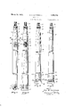
- Figure 1 is an elevational View, partially in section, of a preferred form of drill tool
- Fig. 2 is a side elevational view shown partially in section and taken at right angles to the View shown in Fig. 1;
- FIG. 3 is a side elevational view, partially in section, of a modified form of drill tool
- Fig. 4 is a side elevational view of an additional modification of a tool embodying the invention.
- Fig. 5 is an enlarged side elevational view of the removable cutting tip for the tools shown in Figs. 3 and 4;
- Fig. 6 is a side elevational view taken at right angles to the View shown in Fig. 5 and showing parts broken away;
- Fig. '7 is a sectional view, taken along the lines 77 of-Fig. 5; and V Fig. 8 is a cross sectional view taken on the line 8--8 of Fig. 1.
- Figures 1 and 2 of the drawings show a drill tool embodying the invention and comprising a body portion 1 to: the upper end of which a rope socket 2 is secured by a threaded stud 3 and to the lower end of which a suitable cutting tip 4 is secured by means of a pair of suitable studs 5.
- the body 1 of the drill is of substantially the same sectional area, throughout its length.
- the flattenedblade portion 6' of the lower end of the tool merges very gradually into the upper cylindrical portion, so that there are no zones of abrupt change of section any place in the tool body.
- the tool body is preferably formed of sixty percent carbon and two and one-half percent nickel steel or other suitable high tensile metal that will not shatter or break in service. Forthe most hazardous service the tool body is hardened and tempered over its entire length, whereas for other service only the lower end portion of the tool body is hardened, so that the impact face 7 of the tool will not deform in service.
- the upper end of the tool body has the end face 8 ground to mate with the corresponding face of the rope socket member 2 and is provided with a suitably threadedsocket for receiving the stud 3 that holds the rope socket member to the tool body.
- the upper part of the body portion of the rope socket member 2 is of conventional form embodying. a series of suitable apertures for receiving the rope-securing pins 9 that hold the end oi the drill rope 10 anchored in place. Suitable fishing slips 11 are formed on the upper end of the rope socket member for assistance in fishing for the tool if the rope tears free from therope socket member.' A suitable wrench aperture l2is formed. in the side of the socket member for providing access to the wrench socket 13 that is formed'in the upperend of the securing stud 3. The wrench socket 13 is also accessible from the rope socket through the aperture 14 before the rope end is anchored in place.
- a suitable dowel 15 prevents loosening of the rope socket member by reason of relative movement between the ropesocket member 2 and the tool body 1.
- the anchor stud 3 has a righthand thread on its lower end and alefthand thread. on its upper end for drawing the mating faces of the tool body and the rope socket members together.
- the lower endof the tool body carries the cutting tip 4 that is preferably of the general char- .acter describedand claimed in my copending ap-
- a modified form of tool body 16 is shown in Fig. 3, wherein the cross section of the body is circular over its entire length.
- the hardening and tempering of this form of tool body is the same as for the tool body shown in Figs. 1 and. 2.
- the upper end of the tool body 16 has the rope socket 17 formed directly in the body portion, so that there is no joint any place in the body portion of the tool.
- the lower end of the tool body has a'cutting tip 18 of the character shown in Figs. 5, Sand '7, to which reference may now be had.
- the impact face 19 of the tool is preferably of the general char- .acter describedand claimed in my copending ap-
- the upper end of the tool body 16 has the rope socket 17 formed directly in the body portion, so that there is no joint any place in the body portion of the tool.
- the lower end portion of the tool body 16 is suite ably threaded as at 21 for receiving the'securing sleeve 22 that rigidly connects the tip 18 to. the. f
- the bit tip also has a threaded portion 23 that engages suitable threads offthe sleeve 22.
- the tip-engaging'portion' of the'sleeve' is threaded in the oppositedirection from portion that engages the tool body in order to insure a connection between thebody portion and the bit tip that will remain tight in service; Compression of the metal of the tool 'bodyfand the threaded portion of the tip under impact in ser-' vice tends to tighten this connection in service.
- the sleeve 22 also has suitable wrenchfsquares- 24 formed thereon for facilitating proper tightenengages the tip and tool'body prevents relative movement between these partsin service.
- The, tip member .18 has a collar portion 26 that protects the sleeve 22 from injurious impact with rock pieces in the drill hole and serves-to strengthen the bit tip.
- the cutting face 27 01" the bit tip is of any suitable form for working in the particular ground formation encountered.-
- the tool shown in Fig. 4 difiers from the body of the tool shown in Fig. 3 only in the uniform
- the remaining this tool have herethat the tool herein described has a body portion I wherein there are no points of concentration of impact vibrations andwhere all portions of the body portion are of homogeneous character, high a ing of the sleeve.
- a suitable key 25 that interis r tensile metal. that will not. crack or shatter .in' 7 service and wherein the tool body maybe formed 'of the best character of-metal for the servicerequired ofit.
- a drill bit assembly comprising tip, a drill bit blade of solid section, a rope socket a drill bit carried by said bit blade at one end thereof, an impact face forming a part of said bit tip and being substantially normal to the longitudinal axis of said bit blade assembly, a threaded portion forming a part of said bit tip, an impact face forming a part of said bit blade and being substantially normal to the longitudinal axis of said bit blade and being of contact area and contour that are substantially equivalent to and conforming to the contact area and contour respectively of the impact face forming a part of said bit tip, a threaded portion forming a part of said bit blade and substantially registering with the threaded portion forming a part of said bit tip, separate means continuously mounted on the threaded areas of both said .bit blade and said bit tip and bridging the junction of said bit blade and said bit tip for rigidly joining said bit tip to said bit blade, a plurality of wrench engaging land portions disposed externally of said separate means and separate means adapted for being inter
- a drill bit assembly comprising in combination a substantially tapered drill bit blade having a rope socket end and an impact end, a threaded portion of said bit blade extending from the impact end of said bit blade longitudinally thereof, an annular shoulder forming a part of said bit blade and positioned adjacent said threaded portion, a pair of impact faces forming the impact end of said bit blade and positioned substantially normal to the axis of said bit blade and each in the shape of a substantial segment of a circle and spaced from each other, a bit tip comprising a cutting face, a radially outwardly extending protecting flange disposed adjacent said cutting face and forming a part of said bit tip, a threaded portion of said bit tip adjacent said protecting flange and remote from said cutting face and threaded in a direction opposite to the threads formed on said bit blade, a plurality of spaced impact faces substantially normal to the longitudinal axis of said bit tip and each shaped as a substantial segment of a circle and registering with said impact faces on the bit blade,
Landscapes
- Engineering & Computer Science (AREA)
- Life Sciences & Earth Sciences (AREA)
- Geology (AREA)
- Mining & Mineral Resources (AREA)
- Mechanical Engineering (AREA)
- Physics & Mathematics (AREA)
- Environmental & Geological Engineering (AREA)
- Fluid Mechanics (AREA)
- General Life Sciences & Earth Sciences (AREA)
- Geochemistry & Mineralogy (AREA)
- Earth Drilling (AREA)
Description
March 19, 1935. R. R. SANDERSON DRILL BIT,
2 Sheefs-Sheet l Filed Aug. 8, 1932 INVENTOR Ra -R.,$anderson BY C5 1 L ATTORNEYS DRILL BIT Filed Aug. 8, 1952 2 Sheets-Sheet 2 INVENTOR Ray R.Sanderson ATTORNEYS Patented Mar. 19, 1935 or fice Application August 8,
2 Claims.
5 from breakagebetween tool sections are caused by failure of the connection between the drill blade and the stem, The joint between the rope socket and the stem breaks very rarely, but this joint also fails from time-to-time.
The industrially successful and substantially universally used pin and box joint at the connection between the drill blade and the stem in such.
breakage cases is usually found to be the source of the fracture. Thetransverse waves of impact vibrations set up within the tool each time it dropsare believed to concentrate or localize at the Weaker portions of the tool or where changes are made in the character or'section of metal from which the tool shaft is formed.
In the drilling of deep wells in which the drill tool assembly is from thirty to fifty feet in length and the hole is of small diameter, it is often impossible to recover a lost tool, even when the drilling of the hole has cost many thousands of dollars and when the hole is plugged by a lost tool, the hole cannot be used.
In deep welldrilling, single piece tool assemblies have heretofore been used in'which bit steel is welded to the steel forming the remainder of the tool shaft. These tools-are of great weight, often weighing thousands of pounds, and the tool lengths are such that the tool shaft is subjected to severe strains each timeit is dropped in the hole in the drilling operations. Knowing that the breakage of such a tool in a deep well will most likely result in a loss of all of the'work previously expended in forming the hole, the operators are content to use such single piece tools, even when much time and labor is required for the resharpening of the tool after it becomes dull. These tools are not made of a single character of metal because the bit steel that forms the cutting face of the tool isof too brittle a structure, for the enthe length of shaft and the high tensilesteel used in the remainder of the shaft will not form a good cutting face. Furthermore, the impact vibrations developed in the tool shaft tend to concentrate in the zone of the weld and, since the metal structure is somewhat weakened in this zone, breakage often occurs, even when all possible precautions are observed. This invention proposes a single piece tool shaft wherein there are no portions in which abrupt changes in character or section of metal occur, and which substantially eliminates the hazards from breakage in deep 1932, Serial N0. 627,923
well drilling. In cases where the tool might become stuck in the drill hole because of the particular nature of the ground formation, a removable rope socket of conventional form that would provide a joint member of such form that a jar 5 could be interposed between the rope socket and the single piece tool shaft could be used. This structure is unnecessary, except in special characters of ground formation. The tool with the special form of rope socket joint shown herein or with the rope socket formed in the tool .body without any joint therein is the more satisfactory construction.
One of the objects of the invention is to provide a single piece tool shaft of the most suitable homogeneous character, of metal for the service required and wherein there are no abrupt changes in metal section or character of metal.
Another object of the invention is to provide a single piece homogeneous tool shaft embodying both a bit blade andbit stem of the same character of metal wherein the liability of breakage of the tool shaft is substantially eliminated.
An additional object of the invention is to provide an improved rope socket connection for use withfa. toolof the character set forth. I
Afurther object of the invention is to provide an improved replaceable bit tip construction that may be used satisfactorily. with a tool shaft ,of round section.
Another object of the invention is to provide a single piece tocl shaft and removable drill bit tip construction that greatly extends the operating life of the tool in the drill hole and greatly simplifies the labor of providing a'new cutting face for the tool.
' A further object is to provide a drill tool which is relatively inexpensive to manufacture and which embodies many new advantages not heretofore obtained 'andwhich is quickly and easily assembled.
With the above and other objects in view which will be apparent to those skilled in the art to which the invention appertains, the invention may be said toconsist in the following combinations and. associations of parts shown in the drawings in which,
Figure 1 is an elevational View, partially in section, of a preferred form of drill tool;
Fig. 2 is a side elevational view shown partially in section and taken at right angles to the View shown in Fig. 1;
'Fig. 3 is a side elevational view, partially in section, of a modified form of drill tool;
Fig. 4 is a side elevational view of an additional modification of a tool embodying the invention;
Fig. 5 is an enlarged side elevational view of the removable cutting tip for the tools shown in Figs. 3 and 4;
Fig. 6 is a side elevational view taken at right angles to the View shown in Fig. 5 and showing parts broken away;
Fig. '7 is a sectional view, taken along the lines 77 of-Fig. 5; and V Fig. 8 is a cross sectional view taken on the line 8--8 of Fig. 1.
Figures 1 and 2 of the drawings show a drill tool embodying the invention and comprising a body portion 1 to: the upper end of which a rope socket 2 is secured by a threaded stud 3 and to the lower end of which a suitable cutting tip 4 is secured by means of a pair of suitable studs 5.
The body 1 of the drill is of substantially the same sectional area, throughout its length. The flattenedblade portion 6' of the lower end of the tool merges very gradually into the upper cylindrical portion, so that there are no zones of abrupt change of section any place in the tool body.- The tool body is preferably formed of sixty percent carbon and two and one-half percent nickel steel or other suitable high tensile metal that will not shatter or break in service. Forthe most hazardous service the tool body is hardened and tempered over its entire length, whereas for other service only the lower end portion of the tool body is hardened, so that the impact face 7 of the tool will not deform in service.
The upper end of the tool body has the end face 8 ground to mate with the corresponding face of the rope socket member 2 and is provided with a suitably threadedsocket for receiving the stud 3 that holds the rope socket member to the tool body.
. The upper part of the body portion of the rope socket member 2, is of conventional form embodying. a series of suitable apertures for receiving the rope-securing pins 9 that hold the end oi the drill rope 10 anchored in place. Suitable fishing slips 11 are formed on the upper end of the rope socket member for assistance in fishing for the tool if the rope tears free from therope socket member.' A suitable wrench aperture l2is formed. in the side of the socket member for providing access to the wrench socket 13 that is formed'in the upperend of the securing stud 3. The wrench socket 13 is also accessible from the rope socket through the aperture 14 before the rope end is anchored in place.
A suitable dowel 15 prevents loosening of the rope socket member by reason of relative movement between the ropesocket member 2 and the tool body 1. The anchor stud 3 has a righthand thread on its lower end and alefthand thread. on its upper end for drawing the mating faces of the tool body and the rope socket members together.
The lower endof the tool body carries the cutting tip 4 that is preferably of the general char- .acter describedand claimed in my copending ap- A modified form of tool body 16 is shown in Fig. 3, wherein the cross section of the body is circular over its entire length. The hardening and tempering of this form of tool body is the same as for the tool body shown in Figs. 1 and. 2. The upper end of the tool body 16 has the rope socket 17 formed directly in the body portion, so that there is no joint any place in the body portion of the tool. The lower end of the tool body has a'cutting tip 18 of the character shown in Figs. 5, Sand '7, to which reference may now be had. The impact face 19 of the tool:
body is formed normal to the axis of the tool body and is accurately ground to properly register with the impact face 20 of the bit tip 18.
The lower end portion of the tool body 16 is suite ably threaded as at 21 for receiving the'securing sleeve 22 that rigidly connects the tip 18 to. the. f
The sleeve 22 also has suitable wrenchfsquares- 24 formed thereon for facilitating proper tightenengages the tip and tool'body prevents relative movement between these partsin service.
The, tip member .18 has a collar portion 26 that protects the sleeve 22 from injurious impact with rock pieces in the drill hole and serves-to strengthen the bit tip. The cutting face 27 01" the bit tip is of any suitable form for working in the particular ground formation encountered.-
The tool shown in Fig. 4 difiers from the body of the tool shown in Fig. 3 only in the uniform The remaining this tool have herethat the tool herein described has a body portion I wherein there are no points of concentration of impact vibrations andwhere all portions of the body portion are of homogeneous character, high a ing of the sleeve. A suitable key 25 that interis r tensile metal. that will not. crack or shatter .in' 7 service and wherein the tool body maybe formed 'of the best character of-metal for the servicerequired ofit. The absence of'the joints that cause the greatest hazards in service, andthe absence of any'welded connections in the. shaft,
and the further absence. of abrupt changes in cross sectional contour prevent suchlocalization of stresses in the tool shaft as might resultin breaking the shaft in service.
The'proposed form of rope socket connection character of service. r It is .to be understood thatthe particular embodiments of the invention shown and described .is particularly strong and of light weight and is V of such character as to remain secure-for all are presented for the purposes of illustration and explanation, and that various modifications may be made without departing from the invention as defined-in the appended claims. 7
What I claim is: 1 1. A drill bit assembly comprising tip, a drill bit blade of solid section, a rope socket a drill bit carried by said bit blade at one end thereof, an impact face forming a part of said bit tip and being substantially normal to the longitudinal axis of said bit blade assembly, a threaded portion forming a part of said bit tip, an impact face forming a part of said bit blade and being substantially normal to the longitudinal axis of said bit blade and being of contact area and contour that are substantially equivalent to and conforming to the contact area and contour respectively of the impact face forming a part of said bit tip, a threaded portion forming a part of said bit blade and substantially registering with the threaded portion forming a part of said bit tip, separate means continuously mounted on the threaded areas of both said .bit blade and said bit tip and bridging the junction of said bit blade and said bit tip for rigidly joining said bit tip to said bit blade, a plurality of wrench engaging land portions disposed externally of said separate means and separate means adapted for being interposed between said bit tip and said bit blade for preventing relative rotary movement therebetween.
2. A drill bit assembly comprising in combination a substantially tapered drill bit blade having a rope socket end and an impact end, a threaded portion of said bit blade extending from the impact end of said bit blade longitudinally thereof, an annular shoulder forming a part of said bit blade and positioned adjacent said threaded portion, a pair of impact faces forming the impact end of said bit blade and positioned substantially normal to the axis of said bit blade and each in the shape of a substantial segment of a circle and spaced from each other, a bit tip comprising a cutting face, a radially outwardly extending protecting flange disposed adjacent said cutting face and forming a part of said bit tip, a threaded portion of said bit tip adjacent said protecting flange and remote from said cutting face and threaded in a direction opposite to the threads formed on said bit blade, a plurality of spaced impact faces substantially normal to the longitudinal axis of said bit tip and each shaped as a substantial segment of a circle and registering with said impact faces on the bit blade, a separate key member positioned between said pairs of spaced impact faces of both said bit blade and said bit tip for preventing substantial rotary motion therebetween, a collar having internally disposed threaded portions of opposite direction threads at its opposite ends and adapted for substantially simultaneously threading on the threaded portions of both said bit blade and said bit tip, and a plurality of wrench lands positioned externally of said inwardly threaded collar.
RAY R. SANDERSON.
Priority Applications (1)
| Application Number | Priority Date | Filing Date | Title |
|---|---|---|---|
| US627923A US1994792A (en) | 1932-08-08 | 1932-08-08 | Drill bit |
Applications Claiming Priority (1)
| Application Number | Priority Date | Filing Date | Title |
|---|---|---|---|
| US627923A US1994792A (en) | 1932-08-08 | 1932-08-08 | Drill bit |
Publications (1)
| Publication Number | Publication Date |
|---|---|
| US1994792A true US1994792A (en) | 1935-03-19 |
Family
ID=24516698
Family Applications (1)
| Application Number | Title | Priority Date | Filing Date |
|---|---|---|---|
| US627923A Expired - Lifetime US1994792A (en) | 1932-08-08 | 1932-08-08 | Drill bit |
Country Status (1)
| Country | Link |
|---|---|
| US (1) | US1994792A (en) |
Cited By (16)
| Publication number | Priority date | Publication date | Assignee | Title |
|---|---|---|---|---|
| US4557642A (en) * | 1983-03-15 | 1985-12-10 | Forgacsoloszerszamipari Vallalat | Coupling arrangement for modular tool-systems |
| US4971491A (en) * | 1985-10-15 | 1990-11-20 | Cook Harold D | Tool holder system and method of use |
| US5311654A (en) * | 1992-09-25 | 1994-05-17 | Cook Harold D | Tool holder system and method of making |
| US5582494A (en) * | 1985-10-15 | 1996-12-10 | Cook; Harold D. | Tool holder system and method of use |
| US5975816A (en) * | 1997-07-09 | 1999-11-02 | Cook; Harold D. | Harmonic dampener for rotary tool holder |
| US5979912A (en) * | 1997-07-09 | 1999-11-09 | Cook; Harold D. | Heavy-metal shrink fit cutting tool mount |
| US6035512A (en) * | 1997-07-09 | 2000-03-14 | Cook; Harold D. | Machine tool extension and method of forming the same |
| US6109842A (en) * | 1999-08-03 | 2000-08-29 | Cook; Harold D. | Tool holder with harmonic dampening drive mechanism |
| US6161309A (en) * | 1999-04-28 | 2000-12-19 | Cook; Harold D. | Heat shrink tool holder cooler |
| US6234729B1 (en) | 1999-04-28 | 2001-05-22 | Harold D. Cook | Shrink fit shoulder interface |
| US6382888B2 (en) | 1997-07-09 | 2002-05-07 | Harold D Cook | Vibration dampened spindle and tool holder assembly |
| US6425716B1 (en) | 2000-04-13 | 2002-07-30 | Harold D. Cook | Heavy metal burr tool |
| US20060078372A1 (en) * | 2003-01-30 | 2006-04-13 | Morgan Kanflod | Coupling sleeve for connection of a threaded rock bolt to an impact rock drilling machine |
| US20090155010A1 (en) * | 2007-12-17 | 2009-06-18 | Cook Harold D | Tool holder dampening system |
| US20090205811A1 (en) * | 2008-02-19 | 2009-08-20 | Cook Harold D | Heat shrink tool holder cooling cart |
| US20100272533A1 (en) * | 2009-04-26 | 2010-10-28 | Iscar, Ltd. | Rotary Cutting Tool |
-
1932
- 1932-08-08 US US627923A patent/US1994792A/en not_active Expired - Lifetime
Cited By (19)
| Publication number | Priority date | Publication date | Assignee | Title |
|---|---|---|---|---|
| US4557642A (en) * | 1983-03-15 | 1985-12-10 | Forgacsoloszerszamipari Vallalat | Coupling arrangement for modular tool-systems |
| US4971491A (en) * | 1985-10-15 | 1990-11-20 | Cook Harold D | Tool holder system and method of use |
| US5582494A (en) * | 1985-10-15 | 1996-12-10 | Cook; Harold D. | Tool holder system and method of use |
| US5311654A (en) * | 1992-09-25 | 1994-05-17 | Cook Harold D | Tool holder system and method of making |
| US6382888B2 (en) | 1997-07-09 | 2002-05-07 | Harold D Cook | Vibration dampened spindle and tool holder assembly |
| US5975816A (en) * | 1997-07-09 | 1999-11-02 | Cook; Harold D. | Harmonic dampener for rotary tool holder |
| US5979912A (en) * | 1997-07-09 | 1999-11-09 | Cook; Harold D. | Heavy-metal shrink fit cutting tool mount |
| US6035512A (en) * | 1997-07-09 | 2000-03-14 | Cook; Harold D. | Machine tool extension and method of forming the same |
| US6071219A (en) * | 1997-07-09 | 2000-06-06 | Cook; Harold D. | Method and apparatus for mitigating vibration associated with rotary cutting machines |
| US6161309A (en) * | 1999-04-28 | 2000-12-19 | Cook; Harold D. | Heat shrink tool holder cooler |
| US6234729B1 (en) | 1999-04-28 | 2001-05-22 | Harold D. Cook | Shrink fit shoulder interface |
| US6109842A (en) * | 1999-08-03 | 2000-08-29 | Cook; Harold D. | Tool holder with harmonic dampening drive mechanism |
| US6425716B1 (en) | 2000-04-13 | 2002-07-30 | Harold D. Cook | Heavy metal burr tool |
| US20060078372A1 (en) * | 2003-01-30 | 2006-04-13 | Morgan Kanflod | Coupling sleeve for connection of a threaded rock bolt to an impact rock drilling machine |
| US20090155010A1 (en) * | 2007-12-17 | 2009-06-18 | Cook Harold D | Tool holder dampening system |
| US20090205811A1 (en) * | 2008-02-19 | 2009-08-20 | Cook Harold D | Heat shrink tool holder cooling cart |
| US7886560B2 (en) | 2008-02-19 | 2011-02-15 | Cook Harold D | Heat shrink tool holder cooling cart |
| US20100272533A1 (en) * | 2009-04-26 | 2010-10-28 | Iscar, Ltd. | Rotary Cutting Tool |
| US8596937B2 (en) * | 2009-04-26 | 2013-12-03 | Iscar, Ltd. | Rotary cutting tool |
Similar Documents
| Publication | Publication Date | Title |
|---|---|---|
| US1994792A (en) | Drill bit | |
| US2676820A (en) | Drill collar | |
| US2288124A (en) | Drilling string protector | |
| US1999706A (en) | Coupling | |
| US4108259A (en) | Raise drill with removable stem | |
| US2045520A (en) | Cable tool joint | |
| US2032328A (en) | Drill bit | |
| USRE28310E (en) | Means for removably affixing cutter bit and lug assemblies to driven elements of a mining machine or the like | |
| US3519092A (en) | Percussion bit | |
| US2656153A (en) | Rotary drilling bit | |
| US3917009A (en) | Removable stem for raise bits | |
| US20120125691A1 (en) | Modular drilling system | |
| US2454771A (en) | Drill bit assembly | |
| US1995043A (en) | Drill bit | |
| US2293997A (en) | Method of making tool joints | |
| US2141771A (en) | Sprocket chain construction | |
| US2955804A (en) | Drill bit | |
| US2819880A (en) | Rock drills | |
| US1922559A (en) | Rock drill | |
| US1994791A (en) | Drill bit | |
| US3362489A (en) | Earth auger bifurcated point | |
| US2022055A (en) | Drill bit | |
| US1995389A (en) | Disk bit | |
| US2675219A (en) | Coal cutter chain | |
| US6516904B1 (en) | Mining drill steels and methods of making the same |