US1982982A - Schedule signal clock - Google Patents
Schedule signal clock Download PDFInfo
- Publication number
- US1982982A US1982982A US34022A US3402225A US1982982A US 1982982 A US1982982 A US 1982982A US 34022 A US34022 A US 34022A US 3402225 A US3402225 A US 3402225A US 1982982 A US1982982 A US 1982982A
- Authority
- US
- United States
- Prior art keywords
- clock
- contact
- ring
- disposed
- signal
- Prior art date
- Legal status (The legal status is an assumption and is not a legal conclusion. Google has not performed a legal analysis and makes no representation as to the accuracy of the status listed.)
- Expired - Lifetime
Links
- 239000004020 conductor Substances 0.000 description 27
- 230000003028 elevating effect Effects 0.000 description 13
- 230000033001 locomotion Effects 0.000 description 7
- 230000003190 augmentative effect Effects 0.000 description 3
- 230000006835 compression Effects 0.000 description 2
- 238000007906 compression Methods 0.000 description 2
- 230000003111 delayed effect Effects 0.000 description 2
- 238000003780 insertion Methods 0.000 description 2
- 230000037431 insertion Effects 0.000 description 2
- 238000004904 shortening Methods 0.000 description 2
- 235000014443 Pyrus communis Nutrition 0.000 description 1
- 238000006073 displacement reaction Methods 0.000 description 1
- 230000006870 function Effects 0.000 description 1
- 230000011664 signaling Effects 0.000 description 1
Images


Classifications
-
- G—PHYSICS
- G04—HOROLOGY
- G04C—ELECTROMECHANICAL CLOCKS OR WATCHES
- G04C21/00—Producing acoustic time signals by electrical means
- G04C21/16—Producing acoustic time signals by electrical means producing the signals at adjustable fixed times
- G04C21/30—Producing acoustic time signals by electrical means producing the signals at adjustable fixed times with provision for a number of operations at different times, e.g. ringing the bells in a school
Definitions
- J 1 zMy'inventiom relates toaxscheduleisignakolock; a current ofaminimum voltage and amperage,
- a curved-bearingsurface to' operate in conjunc- :nite: aiJpIi'catiOmIbIit its: application is co-exten-' "tion:with another contact point which is disposed g 'sive tocall ilsesmhereithe same or'like. problems; to.
- a clock mechanism asusually designed and 'nsighalrzclocksz aS'ThGIEtOfOIQI-dGViSBdTfOIY said"'manufactured, for time pieces of moderate cost unp'os'es-sare of :expensiveconstruction; "The cost. lordinarily does not maintain the movement of the 2 of-ainstallation isrlargeg'. orLthe, mechanism is so; hands'with a refined uniform regularity through- 25 intricate and adjustmentsso delicate :that they :outw-theventire three hundred. and sixty degrees,
- z'zi are notxa'dapted toextensive common uses: -Many owing to the play in the cog wheels and associated rtypeshave been.suggested, tsome more simple rthanzxz'mechanism. "Therefore; serious objection obothers, :but' as usually: idesignedc heretofore.
- @prdvid'e :fonans-hour"and-minute 'signabzand have FigJB-isaview in sideelevationwith portions :9 theisignalirepeated-cday'afterday without attenbroken away; m tion; and torprovide. for a-plura lity of such sig- Fig; '4 is a view in perspective ofthe curved con-v 1*. nals. 1: Again, ;mprimary;object ofmmy. invention tactmember of the make and break means;
- Fig. 7 is a view in section on broken dotted line 7, 7 of Fig. 6;
- Fig. 8 is an enlarged fragmentary view in front elevation of a part of the clock dial showing the make and break device in advanced position as respects Fig. 6, showingthe circuit broken;
- Fig. 9 is a view in section on broken dotted line 9, 9 of Fig. 8;
- Fig. 10 is an enlarged view in section of a modified form of clock embodying my invention, said form providing for a multiplicity of circuits through the clock and showing the use of cables as well as the screen ring.
- Fig. 11 is a view in perspective of a brake device which eliminates play or slackness in the gears of the clock mechanism, and insures uniform relative movement of the hands;
- Fig. 12 is a view in perspective of a modified form of a schedule signal clock embodying my in.-
- the clock mechanism member consists of an alarm clock adapted for the D poses of my invention.
- the clock mechanism member is provided with a housing 19.
- This clock mechanism member may be, and preferably is, disposed upon a base member 20, which functions as a housing for certain parts hereinafter set forth.
- the clock mechanism is preferably releasably connected to said base member by means of interlocking posts 21 and 22, Figs. 2 and 3, one part of which 23 and 24 is disposed in the housing of the base member, and the other parts of which 25 and 26 are disposed in the clock mechanism member 19.
- These interlocking posts may be releasably held by means of the resilient member 27, one end of which is snapped under post 28 in the base member.
- the clock shaft 29 of the clock actuating mechanism 30 is provided with the usual hour hand 31 and minute hand 32, back of which'is disposed the clock dial 33, having thereon the usual time divisions and indicia thereof.
- a sheet 34 of gripping non-conducting medium may be secured to said dial.
- two or more concentric rings 35 and 36, respectively, of yielding pressure producing conducting medium are disposed. This medium-may be in the form.
- the shaft 43 of the make and break means as hereinafter set forth may be passed through such a medium by forcing to one side the strands of wire comprising the screen ring or cable. When occasion requires a change in time of signals the shafts are withdrawn and re-inserted at the points of the dial desired.
- the elastic supporting member 34 and the supporting member 37 are provided.
- Such supporting members serve to put the screen or wire cable or ring under compression which actuates the wires back into position after being pressed to one side by the shaft 43 when said shaft 43 is withdrawn.
- This compression of the wire ring or cable is clearly shown in Fig. 10 for rings 105 and 106 where the same are shown considerably flattened.
- the ends of the plurality of wires clearly appear.
- the supporting members 34 and 3''! act in a similar tact with said curved surface;
- a supporting back 37 for said rings is disposed to protect and hold said rings and other parts in position.
- Each of these rings respectively has an electrical contact post 38 and 39, which are preferably connected to the parts 25 and 26 of the in- .terlocking posts by conductors 40 and 41.
- a make and break'means is provided between the clock hands 31 and 32 and the two concentric rings 35 and 36 as follows:
- a contact head (see Figs. 4, 6, 7 and 8), having a curved bearing head 42 mounted on a shaft 43, is provided, so that said shaft may extend through and into either of said rings 35 and 36.
- the other contact head 44 (see Figs. 5, 6, 7 and 8), is formed with a conductor point 45 and an-insulated or non-conducting elevating member or knob 46 disposed in close proximity thereto, the diameter of said knob or elevating member being preferably larger than said conductor point.
- the conductor point 45 is preferably removable and adjustable axially. The longitudinal axis of the head 42 may be adjusted by turning, which provides in part for the length of the alarm or signal given.
- the longitudinal axis of the curved bearing head 42 may be adjusted by turning so that the "time is delayed when the elevating member -will co'me in contact with the curved surface of 'the said bearing; so that the lifting'of the conductor point would be correspondingly delayed, and the duration of the signal would be correspondingly longer.
- the duration of the signal may be made to approach zero by: (a), shortening contact point 45; .'(b), shortening distance between point 45 and knob 46; (c), adjusting the position of the longitudinal axes of the curved bearing head 42 by turning in the proper direction; and, (at), increasing curved magnitude of curved'bearing of head 42;
- the dial of the clock besides being provided with a minute circle 48, is preferably also provided with one or more hour circles 47, afragmentary viewof which dial appears in Fig. 6.
- a contact head 42 is inserted in perforation 49 inthe hour circle in nine oclock position, and another contact head42 is disposed in theperforation 50 in the minute. circle in the sixty cminute'or zero position.
- the circuit willbe completed through the hands of the clock when the conductor point 45 of the hour hand comes in contact with the curved surface of the contact head 42 on the hour circle, and the conductor. point 45 'of the'minute hand comes in contact simultaneously with the curved surface of the contact head 42 in the minute circle,'and will continue so until one conductor point 45 or the other is lifted: away from its respective contact head 42 bythe advance of nonconducting. elevating member 46 upon curved bearing '42. i.
- the base member with its contents and wiring connections, will next be described.
- a switch 51 (Fig. 2), having a contact post v 52 for a bell signal and contact post 53 for a buzzer and contact post 54 for a relay, would be used in connection with an exterior alarm circuit.
- 'A conductor 55 is provided to connect the positive post of the battery to a convenient post 5 6, which post in turn is connected to the post 57, (Fig. 2). of a signal bell 58 by conductor 59.
- Conductor 60 connects the other post of said bell to switch post 52, said switch member 51 being connected by conductor 61 to the hinge 62.
- Conductor 63 connects the negative post 64 of the battery to the hinge 65.
- the mechanism When the signal consists merely of a small bell or buzzer member, which may be positioned within the base member, the mechanism is adapted posed in other rooms. To operate said exterior circuit, it may be necessary to have a source of electrical energy 'of considerably larger magnitude than that which passes through the clock. It will be understood that in a schedule signal clock mechanism it is preferable that the current passing through the local mechanism be small, so as to avoid all difficulties incident to excessive arcing. For this larger service, well known relay devices may be used in their well established manner for operating the larger signal and the relay devices operated by the switch 51.
- the wiring and the mechanism heretofore described have all been based on using the dry battery current as the source of electrical energy in the circuit through the clock, and batteries, transformers, or other electrical source may be substituted and used upon standard equipment wired therefor.
- the emergency button 96 is provided with conductors 97 and 98, which connect it to the hinges 62 and of the cover, so that the interior battery circuit may be completed and an alarm device set in operation regardless of the time, and without disturbing the regular operationof the clock, as will appear from the drawings.
- sockets 99 and 100 with conductors 101 and 102 are provided in the clock mechanism.
- the sockets may receive plugs 103 and 104 corresponding to plugs 83 and 89.
- exterior sockets 99 and 100 could be connected to the posts 23 and 24 of the base member by conductors of any desired length.
- the clock mechanism is readily detachable, so that it may be used apart from any signal mechanism.
- Fig. 10 shows a form of my signal clock in which I provide a plurality of separately insulated rings 105 and 106 of electrically conductive material and further provide a plurality of independently insulated radially disposed bars or springs 107.
- the rings 105 and 106 may be connected with any desired external circuits by posts similar to 38, and electrical connection between contact points 42 and any of the rings 105, 106 may be made by inserting contact pins 108 in holes 109, so that they pass between and in contact with bars 107 and through the rings 105 and 106, it being understood that pin 43 on contact point 42 also makes electrical contact with certain of the bars 107. In this way any desired number of external circuits may be controlled.
- a contact member oblong in form and having a curved bearing surface, said member being radially, angularly adjustable whereby the duration of thecompleted. circuit .is in part controlled.
- a makeand break device embodying a member having an elevating knob anda contact .point disposed in operative-spaced relation 'to each other, said knob having a relativelylarger contact area than said contact point, whereby the duration of the completed circuit is in part controlled.
- a ring of conducting wire screen and a sheet of gripping non-conducting medium disposedon one side of said ring,said'non-conducting medium supporting said ring and augmenting the yielding pressure of said" ring.
- signal clock'.-a releasable electrical contact member a ring-of yielding pressure producing conducting medium in which said member may be releasably held and: a; sheetrro't gripping, non-conducting medium disposed. on one sideof saidring, said non-conducting. medium supporting said ring and augmenting the yielding pressure of said ring.
- a ring of conducting wire screen a sheet of gripping non-conducting medium disposed on one side of said ring; said non-conducting medium supporting'said ring and augmenting the yielding pre'ssureof said ring, and a releasable electrical contactimember laterally engaging said screen.
- a dial provided with a plurality of apertures disposedin a circle; and a plurality of electrically interconnected laterally yielding electrical conductors forming a ring disposed coaxial with and in close proximity to said apertures, whereby means to releasably connect electrical contact members. to any point of the circle of said dial is provided.
- a dial provided with a plurality of apertures disposed in a circle; and a plurality of electrical conductors in the form of a wire screen ring disposed'coaxial with and in close proximity to saidxapertures, whereby means to releasably connect electrical contact members to any point of the'circle of said dial is provided.
- a dial provided with aplurality of apertures disposed in a 'circle a plurality of electrically interconnected laterally yielding electrical conductors forming a ring disposed coaxial with and in close proximity to said apertures; and a sheet of gripping non-conducting medium disposed to bear against'said ring, said non-conducting maximxrrsupporting said ring andaugmenting the lateral pressure between members of said ring.
Landscapes
- Physics & Mathematics (AREA)
- General Physics & Mathematics (AREA)
- Electromechanical Clocks (AREA)
Description
Dec. 4, 1934. J CRQZIER 1,982,982
SCHEDULE SIGNAL CLOCK Filed June 1 1925 3 Sheets-Sheet 1 ATTORNEY Dec. 4, 1934. J. CROZ|ER 1,982,982
SCHEDULE S IGNAL CLOCK Filed June 1 1925 5 Sheets-Sheet 2 INVEN TOR wk Lou/s C/vZ/er BY ATTORNEY Dec. 4, 1934- J. L. CROZIER SCHEDULE SIGNAL CLOCK Filed June 1, 1925 3 Sheets-Sheet 3 w W x mz wi M0 ATTORNEY Patented Dec. 4, 1934 l r PATENT -"osl lcs .1,9s2 ,9s2 :tsonEnULE SIGNAL CLOCK JohnLouiS Crozier, Benton, Wash. .ApplicationJune 1,1925, Serial No. 34,022
i f ie-ol ims. (or zoo- 37) J 1 zMy'inventiomrelates toaxscheduleisignakolock; a current ofaminimum voltage and amperage,
More; particularlmvmy invention-xmelates to: ant so-..that adry battery is sufficient to operate the eielectricallyoperated:schedulersignalLclock. .Lsame, whereby places remote from regular-elec- Forpirrposes obillustration and-z'definiteness ofILtricJpowerplants may be served with my. inven- =uiescr iptiorr,"my rinvention'lwillibe' set forth as 5196- tion. Furthermore, a primary'object of my incificallycapplied to:aisolredulesignaLclockioruse; vention 'is to provide for at'variation in the length "mischoolsi: :But be itzparticularlynoted thatmy oi-the alarm by providing a contact pointhaving driventionzisnot to-bewrestricted to any such 'defi-z .a curved-bearingsurface to' operate in conjunc- :nite: aiJpIi'catiOmIbIit its: application is co-exten-' "tion:with another contact point which is disposed g 'sive tocall ilsesmhereithe same or'like. problems; to. move: relatively with respectto said curved 5 ithndzcdnditions: obtain: Toimention' only a fewrsurface: contact point; said second contact point "of (thefluse's toiwhich mydnvention may be'putmhaving an elevated member or knob operatively r thecsamel may: bezapplied in hospitals to signals disposed in close proximity thereto. A further s1: theorti'mesiforsrfthe: administering of medicinesfp ary Obj of? my invention is Provide a A'gain'; thecs'ai'drinvention is applicable in depotsflsig'nal clock: having the electrical circuit mecha- 7 'iorrthetide'spatcnof mommonscarriers. 14 Also, 'my' nismidisposed-back of the dial member, whereby inventionimaybe readily: applied to the throwing the" same" is' protected ,from weather elements,
iof'aiswitch'rfor the.settingfinto operation ofamech unauthorized meddling and also unintentional anl'snrswhereiit is desiredtofset in motion certainf 'interfe ence W le adjus ng Changing ggsmechanicak devices oit'actuatervalves or electricrr "tact. points for achange of schedule.
switches according.to;somepredetermined plan. A clock mechanism, asusually designed and 'nsighalrzclocksz aS'ThGIEtOfOIQI-dGViSBdTfOIY said"'manufactured, for time pieces of moderate cost unp'os'es-sare of :expensiveconstruction; "The cost. lordinarily does not maintain the movement of the 2 of-ainstallation isrlargeg'. orLthe, mechanism is so; hands'with a refined uniform regularity through- 25 intricate and adjustmentsso delicate :that they :outw-theventire three hundred. and sixty degrees,
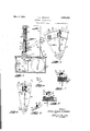
z'zi are notxa'dapted toextensive common uses: -Many owing to the play in the cog wheels and associated rtypeshave been.suggested, tsome more simple rthanzxz'mechanism. "Therefore; serious objection obothers, :but' as usually: idesignedc heretofore. the v-tains tosthe employmentoi thesemore economical 'qcirsimijfificafion has been accompanied byawcorre types of clock-mechanisms to use in a schedule 39 spending reductio inwrange 'or scope or.varia--:: signal :clock mechanism-where a considerable -tion'"of:signa;1ling; rplimary object of myin-t'iidefiniteness and'precision is requisite; Aprimary "ventionis to provide-such'sifschedule"signal clock' bj of mv nv d is to Overcome such Jwhich twin b q i l t cmanufacfiurei-andaf jectionzand to provide a schedule signal clock in which 'will be' economical asrespects its installa whichrthetclock mechanism may consist of one 35 ti'omsimple;economical, and convenient to install? or more of.- these more economical types of clock toloperate without-reduction. inrange ofziimechanisms' signalling. ".zThetxa'bove mentioned general objects of my 7: In employing th hands or theelock: as therxinvention; together with others inherent in the -mounting rmeans for electrical contactnpoints, a".- :same;rare :attainedby the mechanism illustrated iiifllculty atonce encountered in-rthatzthe fric-ii in .the following drawings, the same'being merely '"tioncdevelopedrbythe contacting of; the points izpreferred exemplary forms of embodiment of my must be: of;such:smalk:relativesmagnitudethatr'invention, throughout which drawin s ik said nse oitlie handso will notinterfere with 'saidi'erenceznumerals indicate like parts: cizclockzmechanism indicatingjrithercorrectitime.r A 1 Figure 1 is a view in perspective of a schedule H iprimary objectofrmy invention-is toiprovide, such. rsignaliclockembodyingmy invention; l l
mzanselectsically opratedwignahclock. .1 :Fig.'.2 is'a view in front elevation with portions 7, Anotherzprimaryxobject oi-myninvention is to broken'away to disclose underlying parts;
@prdvid'e :fonans-hour"and-minute 'signabzand have FigJB-isaview in sideelevationwith portions :9 theisignalirepeated-cday'afterday without attenbroken away; m tion; and torprovide. for a-plura lity of such sig- Fig; '4 is a view in perspective ofthe curved con-v 1*. nals. 1: Again, ;mprimary;object ofmmy. invention tactmember of the make and break means;
is tolprovidetiorla'readm changing of.the signals. u ;Fig. 5 is 'aview in perspective of that portion .r..Another-h primary object ofimyninvention is, tom of the make and breakrmeans'disposed uponthe ;'"PIOVidEZfOLfIQIlg or short alarms: and to-pro'vide clock-hand; I
sit; 55::forrtheroperation ofrsuch'argsignalzclock'bmusing .;E'ig. fizishan enlargediragmentaryviewin front elevation of a part of the clock dial showing the make and break device constituting a, part of my invention;
Fig. 7 is a view in section on broken dotted line 7, 7 of Fig. 6;
Fig. 8 is an enlarged fragmentary view in front elevation of a part of the clock dial showing the make and break device in advanced position as respects Fig. 6, showingthe circuit broken;
Fig. 9 is a view in section on broken dotted line 9, 9 of Fig. 8;
Fig. 10 is an enlarged view in section of a modified form of clock embodying my invention, said form providing for a multiplicity of circuits through the clock and showing the use of cables as well as the screen ring.
Fig. 11 is a view in perspective of a brake device which eliminates play or slackness in the gears of the clock mechanism, and insures uniform relative movement of the hands; and
Fig. 12 is a view in perspective of a modified form of a schedule signal clock embodying my in.-
vention, wherein the clock mechanism member consists of an alarm clock adapted for the D poses of my invention.
That portion of my invention, which will be hereinafter referred to as the clock mechanism member is provided with a housing 19. This clock mechanism member may be, and preferably is, disposed upon a base member 20, which functions as a housing for certain parts hereinafter set forth. The clock mechanism is preferably releasably connected to said base member by means of interlocking posts 21 and 22, Figs. 2 and 3, one part of which 23 and 24 is disposed in the housing of the base member, and the other parts of which 25 and 26 are disposed in the clock mechanism member 19. These interlocking posts may be releasably held by means of the resilient member 27, one end of which is snapped under post 28 in the base member.
In the clock mechanism member, the clock shaft 29 of the clock actuating mechanism 30 is provided with the usual hour hand 31 and minute hand 32, back of which'is disposed the clock dial 33, having thereon the usual time divisions and indicia thereof. To said dial, preferably on the back side, a sheet 34 of gripping non-conducting medium may be secured. Upon said'sheet two or more concentric rings 35 and 36, respectively, of yielding pressure producing conducting medium are disposed. This medium-may be in the form.
of a wire screen as illustrated for rings 85 and 36 in Fig. 2, or the medium may be in the form of twisted wire rings or cables as shown at 105 and 106 Fig. 10. Manifestly, the shaft 43 of the make and break means as hereinafter set forth may be passed through such a medium by forcing to one side the strands of wire comprising the screen ring or cable. When occasion requires a change in time of signals the shafts are withdrawn and re-inserted at the points of the dial desired. To
more positively insure contact after successive insertions even at the same point, the elastic supporting member 34 and the supporting member 37 are provided. Such supporting members serve to put the screen or wire cable or ring under compression which actuates the wires back into position after being pressed to one side by the shaft 43 when said shaft 43 is withdrawn. This compression of the wire ring or cable is clearly shown in Fig. 10 for rings 105 and 106 where the same are shown considerably flattened. In Fig. 10, the ends of the plurality of wires clearly appear. The supporting members 34 and 3''! act in a similar tact with said curved surface;
manner on the wire screen when in a fiat annular ring 36, Fig. 2-the strands forming the meshes being actuated back into the original position occupied previous to the distortion incident to the shaft 43 pushing the wire to one side when the shaft was inserted. Manifestly, not only do the supporting members 34 and 37 by pressing the strands together tend to resist displacement or warping vertically, but also laterally, thereby insuring a positive firm contact with shaft 43 at all times upon successive insertions of the shaft 43. Thus is provided an exceedingly efficient and at the same time economical means for signals atv all time divisions of the dial without separate sockets. In my invention the dial may be pierced at any time point in the annular ring so that even signals to the fraction of a minute may be made. Upon the rear side of said rings, a supporting back 37 for said rings is disposed to protect and hold said rings and other parts in position. Each of these rings respectively has an electrical contact post 38 and 39, which are preferably connected to the parts 25 and 26 of the in- .terlocking posts by conductors 40 and 41.
A make and break'means is provided between the clock hands 31 and 32 and the two concentric rings 35 and 36 as follows: A contact head, (see Figs. 4, 6, 7 and 8), having a curved bearing head 42 mounted on a shaft 43, is provided, so that said shaft may extend through and into either of said rings 35 and 36. The other contact head 44, (see Figs. 5, 6, 7 and 8), is formed with a conductor point 45 and an-insulated or non-conducting elevating member or knob 46 disposed in close proximity thereto, the diameter of said knob or elevating member being preferably larger than said conductor point. The conductor point 45 is preferably removable and adjustable axially. The longitudinal axis of the head 42 may be adjusted by turning, which provides in part for the length of the alarm or signal given.
As respects the other contact points 42: These points may be disposed in the longitudinal axis of the clock hand, or they may be disposed otherwise as respects said axis. q
Some conditions require signals to. be of longer duration than other signals. It is therefore important'for a schedule signal clock to have the length of its alarms or signals capable of being varied. This varying of the length of signals is accomplished through the curved bearing heads as follows, (see Figs. 6, 7, 8, and 9) The length .of said signal or alarm depends upon: (a), the
direction of the longitudinal axis of the curved bearing head 42;, (b), the relative difference in length of the conductor point 45 and the elevating member or knob 46; (c), the difference in distance between the said conductor point 45 and the elevating member or knob 46; and, (d), the degree of, curvature of the curved bearing of the head 42 relative to (a), (b), and (c) above. This appears "from a consideration of said figures, since it is clear, as appears in Fig. 7, when the conductor point 45 touches the surface of the curved bearing head 42, the circuit as will ap; pear hereinafter is completed, and said circuit will be completed until the movement of the hand brings the elevating member 46 into con- Thereupon, as the further movement of the hand pushes the insulated elevating member 46 upon the curved surface of the head 42, the conductor point 45 is elevated and lifted above, or rides away from, the said curved surface of the head, so that the circuit is broken, as it appears from the position illustrated in Fig. 9. "Manifestly, if there is only aslight difference in relative length' of the conductor point and the said elevating member,
said contact will be longen'continued for the positions indicated in the drawings, and, manifestly, the longitudinal axis of the curved bearing head 42 may be adjusted by turning so that the "time is delayed when the elevating member -will co'me in contact with the curved surface of 'the said bearing; so that the lifting'of the conductor point would be correspondingly delayed, and the duration of the signal would be correspondingly longer. The duration of the signal may be made to approach zero by: (a), shortening contact point 45; .'(b), shortening distance between point 45 and knob 46; (c), adjusting the position of the longitudinal axes of the curved bearing head 42 by turning in the proper direction; and, (at), increasing curved magnitude of curved'bearing of head 42;
The dial of the clock, besides being provided with a minute circle 48, is preferably also provided with one or more hour circles 47, afragmentary viewof which dial appears in Fig. 6. To illustrate themethod of setting and adjusting the contact heads to give the signals at different time periods, the. following example will be set forth: We will assume that it is desired to give a signal at nine oclock. To this end, a contact head 42 is inserted in perforation 49 inthe hour circle in nine oclock position, and another contact head42 is disposed in theperforation 50 in the minute. circle in the sixty cminute'or zero position. Thus, it is clear that, assuming for the presentthat the posts 38 and 39 are operatively connected to a source of electrical energy,
the circuit willbe completed through the hands of the clock when the conductor point 45 of the hour hand comes in contact with the curved surface of the contact head 42 on the hour circle, and the conductor. point 45 'of the'minute hand comes in contact simultaneously with the curved surface of the contact head 42 in the minute circle,'and will continue so until one conductor point 45 or the other is lifted: away from its respective contact head 42 bythe advance of nonconducting. elevating member 46 upon curved bearing '42. i.
It is obvious that any number of signals may be. setland that these-signals will be repeated day after day without change.
The base member, with its contents and wiring connections, will next be described.
A switch 51, (Fig. 2), having a contact post v 52 for a bell signal and contact post 53 for a buzzer and contact post 54 for a relay, would be used in connection with an exterior alarm circuit.
'A conductor 55 is provided to connect the positive post of the battery to a convenient post 5 6, which post in turn is connected to the post 57, (Fig. 2). of a signal bell 58 by conductor 59. Conductor 60 connects the other post of said bell to switch post 52, said switch member 51 being connected by conductor 61 to the hinge 62. Conductor 63 connects the negative post 64 of the battery to the hinge 65.
Obviously, therefore.
- when the hands of the clock are in such position as to complete the circuit as heretofore described and the switch 51 is closed, there would be a completing of the circuit through the bell signal 53, which would cause the same to ring and give the alarm.
When the signal consists merely of a small bell or buzzer member, which may be positioned within the base member, the mechanism is adapted posed in other rooms. To operate said exterior circuit, it may be necessary to have a source of electrical energy 'of considerably larger magnitude than that which passes through the clock. It will be understood that in a schedule signal clock mechanism it is preferable that the current passing through the local mechanism be small, so as to avoid all difficulties incident to excessive arcing. For this larger service, well known relay devices may be used in their well established manner for operating the larger signal and the relay devices operated by the switch 51.
The wiring and the mechanism heretofore described have all been based on using the dry battery current as the source of electrical energy in the circuit through the clock, and batteries, transformers, or other electrical source may be substituted and used upon standard equipment wired therefor.
There may be occasions to have an alarm given in cases of emergency, such as a fire in a school building, without waiting until the circuit might beclosed through the clock hands to operate the alarm. To this end, the emergency button 96 is provided with conductors 97 and 98, which connect it to the hinges 62 and of the cover, so that the interior battery circuit may be completed and an alarm device set in operation regardless of the time, and without disturbing the regular operationof the clock, as will appear from the drawings.
On the other hand, there may be, occasions, such as during the night when it may not be desired to have the signals given, and to this end, all that is necessary is to move the switch member 51 into intermediate or non-engaging position with respect to the switch posts 52, 53, and 54, Fig. 2.
For some purposes, it may be desirable to have the base member in a locked compartment, 1. e., more or less remote from the clock mechanism proper. To this end, sockets 99 and 100 with conductors 101 and 102 are provided in the clock mechanism. The sockets may receive plugs 103 and 104 corresponding to plugs 83 and 89. In this instance, exterior sockets 99 and 100 could be connected to the posts 23 and 24 of the base member by conductors of any desired length.
As illustrated, the clock mechanism is readily detachable, so that it may be used apart from any signal mechanism.
Fig. 10 shows a form of my signal clock in which I provide a plurality of separately insulated rings 105 and 106 of electrically conductive material and further provide a plurality of independently insulated radially disposed bars or springs 107. The rings 105 and 106 may be connected with any desired external circuits by posts similar to 38, and electrical connection between contact points 42 and any of the rings 105, 106 may be made by inserting contact pins 108 in holes 109, so that they pass between and in contact with bars 107 and through the rings 105 and 106, it being understood that pin 43 on contact point 42 also makes electrical contact with certain of the bars 107. In this way any desired number of external circuits may be controlled.
Obviously, changes may be made in the forms, dimensions and arrangements of the parts of my invention, without departing from the principle thereof, the above setting aiortlr only 5. preferred formsot embodiment.
Iclaim:
I. In combination with an'electrically operat ed schedulexsignal clock, two electrical contacting members disposed for relative movement :one with the-other; one of said. members having, a conductor point and an elevating knob in operatlvei'spaced relation to each other, and the other 0! saidlmembers.being formed withv a curved hearing surface;
2. In combination with an electrically operated schedule signal clock, a contact member oblong in form and having a curved bearing surface, said member being radially, angularly adjustable whereby the duration of thecompleted. circuit .is in part controlled.
3. hi combinationwith an electrically operated schedule signal clock, a make and break device embodyinga'member having an elevating knob and a contact point in operatively disposed spaced relation to each other, whereby the duration of the completed circuit is in part controlled.
4. In combination with an electrically operated schedulesignal clock; a. makeand break device embodying a member having an elevating knob anda contact .point disposed in operative-spaced relation 'to each other, said knob having a relativelylarger contact area than said contact point, whereby the duration of the completed circuit is in part controlled. I v
5. In an. electricallysoperated schedule signal clock, a ring of conducting wire screen and a sheet of gripping non-conducting medium disposedon one side of said ring,said'non-conducting medium supporting said ring and augmenting the yielding pressure of said" ring.
6.-Inanelectrically operated schedule signal clock, a releasable electrical contact member and a ring 01' yielding pressure producing conducting medium in which said'member may be releasably 7. In an electrically operated schedule signal clock, a releasable electrical contact member and a ring of conducting wire screen in which said member may be releasably held.-
8. In an electrically operated schedule. signal clock'.-a releasable electrical contact member, a ring-of yielding pressure producing conducting medium in which said member may be releasably held and: a; sheetrro't gripping, non-conducting medium disposed. on one sideof saidring, said non-conducting. medium supporting said ring and augmenting the yielding pressure of said ring.
9. In an electricallyoperated schedule signal clock, a ring of conducting wire screen, a sheet of gripping non-conducting medium disposed on one side of said ring; said non-conducting medium supporting'said ring and augmenting the yielding pre'ssureof said ring, and a releasable electrical contactimember laterally engaging said screen.
10. In combination with an electrically operated schedule signal. clock, .two electrical contacting members disposed for relative movement one with the other, one of said members having a conductor point and an elevating knob in operative spaced relation to each other and the other'of said members being oblong in. .form and having a curved bearing surface, said member being radially angularly adjustable whereby the duration of the completed circuit is in part controlled.
11. In an electrically .operated schedule. signal clock, a dial provided with a plurality of apertures disposedin a circle; and a plurality of electrically interconnected laterally yielding electrical conductors forming a ring disposed coaxial with and in close proximity to said apertures, whereby means to releasably connect electrical contact members. to any point of the circle of said dial is provided.
-12.'In an electrically operated'schedule signal :clock, a dial provided with a plurality of apertures disposed in a circle; and a plurality of electrical conductors in the form of a wire screen ring disposed'coaxial with and in close proximity to saidxapertures, whereby means to releasably connect electrical contact members to any point of the'circle of said dial is provided.
13. In an electrically operated schedule signal clock, a. dial provided with aplurality of apertures disposed in a 'circle a plurality of electrically interconnected laterally yielding electrical conductors forming a ring disposed coaxial with and in close proximity to said apertures; and a sheet of gripping non-conducting medium disposed to bear against'said ring, said non-conducting mediuxrrsupporting said ring andaugmenting the lateral pressure between members of said ring.
JOHN LOUISv CROZIER.
Priority Applications (1)
| Application Number | Priority Date | Filing Date | Title |
|---|---|---|---|
| US34022A US1982982A (en) | 1925-06-01 | 1925-06-01 | Schedule signal clock |
Applications Claiming Priority (1)
| Application Number | Priority Date | Filing Date | Title |
|---|---|---|---|
| US34022A US1982982A (en) | 1925-06-01 | 1925-06-01 | Schedule signal clock |
Publications (1)
| Publication Number | Publication Date |
|---|---|
| US1982982A true US1982982A (en) | 1934-12-04 |
Family
ID=21873824
Family Applications (1)
| Application Number | Title | Priority Date | Filing Date |
|---|---|---|---|
| US34022A Expired - Lifetime US1982982A (en) | 1925-06-01 | 1925-06-01 | Schedule signal clock |
Country Status (1)
| Country | Link |
|---|---|
| US (1) | US1982982A (en) |
Cited By (4)
| Publication number | Priority date | Publication date | Assignee | Title |
|---|---|---|---|---|
| US2658963A (en) * | 1949-03-01 | 1953-11-10 | Nielsen A C Co | Rotary multiple contact switch |
| US2784266A (en) * | 1949-03-01 | 1957-03-05 | Nielsen A C Co | Rotary multiple contact switch |
| US2861138A (en) * | 1953-07-13 | 1958-11-18 | Philips Corp | Arrangement for switching clocks |
| US3710045A (en) * | 1970-12-09 | 1973-01-09 | Ti Mind Inc | Multiple contact program timer with adjustable conductive brush means and resettable conductive pins |
-
1925
- 1925-06-01 US US34022A patent/US1982982A/en not_active Expired - Lifetime
Cited By (4)
| Publication number | Priority date | Publication date | Assignee | Title |
|---|---|---|---|---|
| US2658963A (en) * | 1949-03-01 | 1953-11-10 | Nielsen A C Co | Rotary multiple contact switch |
| US2784266A (en) * | 1949-03-01 | 1957-03-05 | Nielsen A C Co | Rotary multiple contact switch |
| US2861138A (en) * | 1953-07-13 | 1958-11-18 | Philips Corp | Arrangement for switching clocks |
| US3710045A (en) * | 1970-12-09 | 1973-01-09 | Ti Mind Inc | Multiple contact program timer with adjustable conductive brush means and resettable conductive pins |
Similar Documents
| Publication | Publication Date | Title |
|---|---|---|
| US1982982A (en) | Schedule signal clock | |
| US1716373A (en) | Signal-controlling switch | |
| US889533A (en) | Illuminating electric clock and call system. | |
| US1573371A (en) | Oil-circulation signal | |
| US2477857A (en) | Annunciator | |
| US1469887A (en) | Electric alarm clock | |
| US1091465A (en) | Signaling system. | |
| US1789057A (en) | Time switch | |
| US1050765A (en) | Time-controlled alarm system for telephone-exchanges. | |
| US481919A (en) | Electric guest-call | |
| US3752943A (en) | Multiple memo timing device with adjustable pin conductors | |
| US344072A (en) | Chronometer electric call | |
| US1466471A (en) | Time-control signal system | |
| US984534A (en) | Mutiple electric-light switch. | |
| US1199023A (en) | Electric signal apparatus. | |
| US1237517A (en) | Program-clock. | |
| US659479A (en) | Electric program-clock. | |
| US680059A (en) | Electrical call or alarm device. | |
| US1707784A (en) | Switch device for alarm circuits | |
| US2447370A (en) | Amusement and educational device | |
| US741431A (en) | Electric program-clock. | |
| US1510446A (en) | Bell ringer | |
| US1787059A (en) | Electric clock | |
| US1506264A (en) | Electric alarm | |
| US885953A (en) | Electrical attachment for clocks. |