US1982970A - Tank gauge - Google Patents
Tank gauge Download PDFInfo
- Publication number
- US1982970A US1982970A US68473533A US1982970A US 1982970 A US1982970 A US 1982970A US 68473533 A US68473533 A US 68473533A US 1982970 A US1982970 A US 1982970A
- Authority
- US
- United States
- Prior art keywords
- tank
- float
- weight
- cable
- water
- Prior art date
- Legal status (The legal status is an assumption and is not a legal conclusion. Google has not performed a legal analysis and makes no representation as to the accuracy of the status listed.)
- Expired - Lifetime
Links
- XLYOFNOQVPJJNP-UHFFFAOYSA-N water Substances O XLYOFNOQVPJJNP-UHFFFAOYSA-N 0.000 description 30
- 239000000446 fuel Substances 0.000 description 11
- 239000007788 liquid Substances 0.000 description 10
- 210000002445 nipple Anatomy 0.000 description 3
- PEDCQBHIVMGVHV-UHFFFAOYSA-N Glycerine Chemical compound OCC(O)CO PEDCQBHIVMGVHV-UHFFFAOYSA-N 0.000 description 2
- 238000003776 cleavage reaction Methods 0.000 description 2
- 238000010276 construction Methods 0.000 description 2
- 239000003350 kerosene Substances 0.000 description 2
- 230000007017 scission Effects 0.000 description 2
- 101150103105 Agtrap gene Proteins 0.000 description 1
- 230000000694 effects Effects 0.000 description 1
- 238000004880 explosion Methods 0.000 description 1
- 239000007789 gas Substances 0.000 description 1
- 235000011187 glycerol Nutrition 0.000 description 1
- 239000002184 metal Substances 0.000 description 1
- 238000000034 method Methods 0.000 description 1
- 239000000203 mixture Substances 0.000 description 1
- 238000012856 packing Methods 0.000 description 1
Images
Classifications
-
- G—PHYSICS
- G01—MEASURING; TESTING
- G01F—MEASURING VOLUME, VOLUME FLOW, MASS FLOW OR LIQUID LEVEL; METERING BY VOLUME
- G01F23/00—Indicating or measuring liquid level or level of fluent solid material, e.g. indicating in terms of volume or indicating by means of an alarm
- G01F23/30—Indicating or measuring liquid level or level of fluent solid material, e.g. indicating in terms of volume or indicating by means of an alarm by floats
- G01F23/40—Indicating or measuring liquid level or level of fluent solid material, e.g. indicating in terms of volume or indicating by means of an alarm by floats using bands or wires as transmission elements
- G01F23/42—Indicating or measuring liquid level or level of fluent solid material, e.g. indicating in terms of volume or indicating by means of an alarm by floats using bands or wires as transmission elements using mechanically actuated indicating means
-
- Y—GENERAL TAGGING OF NEW TECHNOLOGICAL DEVELOPMENTS; GENERAL TAGGING OF CROSS-SECTIONAL TECHNOLOGIES SPANNING OVER SEVERAL SECTIONS OF THE IPC; TECHNICAL SUBJECTS COVERED BY FORMER USPC CROSS-REFERENCE ART COLLECTIONS [XRACs] AND DIGESTS
- Y10—TECHNICAL SUBJECTS COVERED BY FORMER USPC
- Y10T—TECHNICAL SUBJECTS COVERED BY FORMER US CLASSIFICATION
- Y10T137/00—Fluid handling
- Y10T137/8158—With indicator, register, recorder, alarm or inspection means
- Y10T137/8342—Liquid level responsive indicator, recorder or alarm
Definitions
- This invention relates to tank gauges and parthe tank.
- the tank ⁇ always ticularly to the type. known as cleavage line and fil-led with liquid of some kind.
- Thispractice has full"v head gauges, the object being to provide resulted in somediiculties in measuring or' asan ⁇ improved construction which functions to certaining the exact quantity .of fuel ⁇ in .the
- a further object of the invention isv to provide sary*I tol draw off..the fuel', namely, the oil 4, is a tank gauge for indicating the level of one toA open the outlet 3 and allow the.v fuel to run 1,5 of two liquids in a tank, the. structure being out as the.l water'is forced in.. Outlet 3 ⁇ , of course, Z0, such that, part ofthe mechanism is arranged is extended' tol the desired point of utilization within lthe tank and partexteriorly thereof, the and one. or more ⁇ valves are arranged in this part ⁇ arranged exteriorly of the tank including outlet as desired. By opening these valves the an ⁇ indicating structure, while the part aroil. is ⁇ allowed to escape. and, consequently, ⁇ the ranged interiorly of the tank includes a oat for water line 5i will move upwardly..
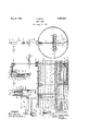
- FIG. 1 is a longitudinal vertical sectional isY also welded to the various containers or view through part of a tank ⁇ with an embodiment closed tubes 7 so that the cable 1.07 may be con- 8,0 of the invention applied thereto, said embodinected therewith and mayy be actuated by the ment being shown partly in section; float.
- Each of. the bars 8. is provided with an Figure 2 isv a sectional view through Figure aperture for accommodatingathe respective posts 1,.
- a clipV or ring 1.5 is snapped' into 100 gasoline or .similar combustible fuels, to ⁇ force place as shown in Fig. 4, and the post is then water into the tank as the fuel is removed therein operative position. from.
- ThisV is. to.y prevent splashing of the oil, VConnected to tank 1 in any desired manner, particularly where the oil ⁇ is very light as, for preferablyy between posts 11 and 12 near the 5,0 instance, kerosene or gasoline.
- housing orhollow block 105 splashes considerably gases are formed and the 16 which carries a pulley 17 over which the danger of explosion is increased.
- said cable also passing through danger it isA customary in war vessels and other pipe 18 which is connected to housing 16 and vessels to. force the water in at the bottom of toa similar housing 19.
- Housing 19 ⁇ has a pipe tank ⁇ as. the fuel isforced fromv the top- ⁇ of 20 connected therewith, which extends dotm- .1.10 f
- a pipe 22 connects this housing 21 to a trap 23 which may be a round, square or other shaped container having an opening 24 in the upper wall.
- a pipe 25 connects the lower part of trap 23 with housing 26 which housing carries a pipe 27 extending up- Wardlyandthrough a packing box 28 to -a desired point above tank 1 where it is connected to a housing 29 carrying pipe 30, which in turn is connected to a comparatively large housing 31, which housing has a hollow tubular extension 32. It will be understood that in housings 19,
- pulleys 21, 26 and 29 are arranged pulleys preferablyV identical with pulley 17r so that the ca blel,y may be readily passed over thesel various pulleys and through the lower part of trap 23 freely.
- a check valve 33 is connectedto pipe 27 at ⁇ 34 so that water or other liquid may be forced into pipe 27 but not drawn therefrom, the valve functioning only as indicatedby the arrow 35.
- a check' valve 36 is connected to the top of housing 21 and opens as indicated by the arrow 37 whereby liquid may be inserted to but not withdrawn therefrom.
- the cable 10 passing through pipe 30 enters what may be termed an indicator 38 and is rigidly secured to a pulley or drum 39 rotatably mounted on shaft 40.
- a smalldrurn 41 is rigidly secured to drum 39 and has one end of the auxiliary cable 42 connected therewith, whereby as drum 39 unwinds drum 41 willwind and will raise the auxiliary cable 42 and the primary weight 43.
- This weight has a flange or head 44 at the lower end which acts in the double capacity of an indicating bar, as illustrated in Fig. 2, .and as a supporting member for the auxiliary weight 45, as shown in Fig. 3.
- Weight 45 is provided with an annular groove 46 and the end rof rod 47 is positioned to fit into this groove.
- This groove may be V-shaped in cross section as shown in the drawing, and if so the head 48 Will be of corresponding shape.
- Rod 47 has an actuating and holding handle 49 which is adapted tobe swung around and passed over the hook 50 when the weight 45 is held in an inoperative position.
- the indicator 38 is filled with a mixture of Water and glycerine so that the various parts just described will operate in this solution, while pipes 27 and 30 are usually filled With water as Well as the trap-23 and pipe20 up to the vent 51. As the water line 5"moves upwardly the water in pipe 20 will naturally move upwardly and any gasoline in this pipe and the housings 16 and 19 .will be gradually forced out through the opening in housing 16.
- the stuiiing box 28 is fixed and stationary, as pipe 27 is clamped in position and the cable 10 moves freely back and forth in this pipe.
- the parts are usually adjusted so that the weight 45 will be held raised, whereby the float 6 Will be on the bottom of the tank, thus indicating that the tank is filled with oil, gasoline or similar liquid.
- flange 44 acting as a pointer or indicator will accordingly rise, so that a fireman or other operator will readily observe this action and see the speed at which the fuel is being fed from the tank and also the amount of fuel left in the tank.
- trap 23 When the water is drawn out, the water in trap 23 remains so that oil cannot enter pipe 27.
- an exterior trap such as trap 52, shown in Fig. 5, may be used.
- trap 23 the pipes or nipples 22 and 25 are connected to the trap on the bottom, while Atrap 52 is associated with pulley housing 26 near the bottom of the trap, whereby the cable 10 may pass over the pulleys in the respective housings through the respective nipples 54 and 55 and through the trap 52 which is continually filled with water.
- pipe 27' shown in Fig. 5, is connected up in some way as pipe 27 and is associated with some kind of indicator as shown in Fig. 1, and designated 38. All the parts shown in Fig. 5 are identical to those shown in Fig. 1 except for the fact that the trap 52 is exterior of the tank and that the housings 26 and 53 and associated parts are slightly differently ar-V ranged for the reasons above set forth.
- a cleavage line and full head tank gauge comprising a float, an indicating ⁇ structure, and means actuated by the float for causing the indicating structure to function, said indicating structure including a pair of Weights counterbalancing said oat, and means for holding one weight out of functioning position, one of said weights causing said float to float on a given1 liquid, and both of said weights causing said iloat to iioat on a lighter liquid.
- a tank gauge of the character described for indicating the level of one or two liquids in a tank comprising a float adapted to be positioned in a tank, means for guiding said float in its upward and downward movement, a cable pulled by said iioat in one direction, a weight for pulling said cable in the opposite direction, said weight counterbalancing said ioat so that it will float on a certain liquid, a secondary weight, means for holding said secondary weight out of engagement with the iirst mentioned weight, said means being adjustable to a position to permit said secondary weight to be raised with the rst mentioned weight whereby said float will float on the surface of a lighter uid, and means coacting with the first mentioned weight for indicating the position of the float in said tank.
- a float In a tank gauge of the character described, a float, a cable connected with said iloat and adapted to be pulled thereby, means including pulleys for guiding the cable to a given point,
- a drum connected to the end of said cable, a second drum connected to the first mentioned drum, an auxiliary cable wound on the second drum, a Weight carried by said auxiliary cable acting to counterbalance to a certain extent said float so as to cause the float toy float on water, an auxiliary weight, means for normally supporting lthe auxiliary weight above the first mentioned weight, a manually actuated member for releasing the auxiliary weight to allow it to rest on the rst mentioned weight whereby said iioat will be counterbalanced sufficiently to cause the same to lioat on oil, and means coacting' with the rst mentioned weight to indicate the position of the iioat in a tank.
- a tank gauge for a tank adapted to contain water and oil, a float arranged in the tank, means for guiding the iioat in its upward and downward movement, a cable connected to said float, means including a tubular structure for guiding said cable to a high point in said tank, and then to a low point in said tank, and finally to a point above the tank exteriorly thereof, said tubular means including a water trap having openings in the upper part whereby when the water in the tank is removed andreplaced with oil said oil cannot pass through said trap and into the pipe leading exteriorly of said tank, and means actuated by said cable exteriorly of the tank for indicating the position of the float in the tank.
- a tank gauge including a iioat, an indicator, means actuated by the tank for actuating the indicator, said means including a cable, said indicator including a drum adapted to be rotated by said cable, an auxiliary drum connected with the rst mentioned drum, an auxiliary cable wound on the auxiliary drum, a primary weight carried by said auxiliary cable, a secondary weight adapted to rest on the primary weight so that both weights will act on both of said cables for counterbalancing said float, means including graduations for showing the position of the lower end of said primary weight and the relative position of said oat in said tank, and manually actuated means for raising and holding said auxiliary weight out of operative contact with said primary Weight.
- a float a cable actuated by said iloat, an indicator actuated by said cable, said indicator including a weight for counterbalancing said float to a certain extent, said weight having a flange at the lower end, an auxiliary tubular weight slidingly fitting over the lower end of the primary weight and adapted to rest on said flange, and a manually actuated structure for raising said auxiliary Weight and holding the same out of contact with said flange whereby the primary weight may function independently.
- a tank gauge comprising a float adapted to be positioned in a tank, a cable extending from said oat, to a point exteriorly of the tank, and an indicator actuated by said cable, said indicator including a weight adapted to be raised as said cable is pulled in one direction by the float and adapted to move downwardly as the float moves upwardly, an auxiliary weight associated with the irst mentioned weight and adapted to coact with the auxiliary weight when in one position to counterbalance to a greater extent said float, and a reciprocating rod adapted to move said auxiliary weight to nonfunctioning position so that said float will be l counterbalanced only by the iirst mentioned weight, thus providing at will two float counterbalancing members, one counterbalancing the oat sufficiently to cause the same to float on Water and the combined weights counterbalanc ing the float so that it will iioat on oil.
Landscapes
- Physics & Mathematics (AREA)
- Fluid Mechanics (AREA)
- General Physics & Mathematics (AREA)
- Level Indicators Using A Float (AREA)
Description
D.4,1934. 'RST/1R 1,982,970
TANK GAUGE Fi1ed Aug. 11, 1953 IM ,II III |"ilf' I MINIMUM, A111111 1,1
1' |||H' III INVENTOR ,III IIT ATTOR EYS JI N Q Q WITNESSES Patented Dec. 4, 1934 l ff t. z f
UNiTlazn STATI-:Sg Vl#a'risN'r .olii-*icsy TANK GAUGE Richard star, Brooklyn, N. Ya Frank Kruth administrator of saidRichard Star, deceased Application August 11, 193s,- s'erial No. 684,735
' 7 Claims. (Cl. Z3- 82) This invention relates to tank gauges and parthe tank. By this method the tank` always ticularly to the type. known as cleavage line and fil-led with liquid of some kind. Thispractice has full"v head gauges, the object being to provide resulted in somediiculties in measuring or' asan` improved construction which functions to certaining the exact quantity .of fuel `in .the
tell at all times the amount of gasoline 0r oil in tank at any time., The, invention` of the present 60 a tank,` as well as the amount of water therein. application presents a' gauge for indicating the Another object ofthe present invention is to amount of. fueli and also the amount of.' water provide an improved tankgauge using a float in the tank. t as an actuator and with the parts so arranged The tank 1; .is provided witha. water inlet 2 that an indicator will cause the fioat at one near the bottom, while. at the top a fuel. outlet 65 time,` to float only on the water and at another 3. is provided. Ordinarily water enters. the` inlet time to float. only kon vthe oilor gasoline. 2 under some pressure so that all'thaty is, neces:-
A further object of the invention isv to provide sary*I tol draw off..the fuel', namely, the oil 4, is a tank gauge for indicating the level of one toA open the outlet 3 and allow the.v fuel to run 1,5 of two liquids in a tank, the. structure being out as the.l water'is forced in.. Outlet 3^, of course, Z0, such that, part ofthe mechanism is arranged is extended' tol the desired point of utilization within lthe tank and partexteriorly thereof, the and one. or more` valves are arranged in this part` arranged exteriorly of the tank including outlet as desired. By opening these valves the an` indicating structure, while the part aroil. is` allowed to escape. and, consequently,` the ranged interiorly of the tank includes a oat for water line 5i will move upwardly..
actuating the indicator and a liquid trap for Arranged within tank 1 isf a float6 whichis preventing oil from passing to the indicator. shown as: consisting of a number ofv metal tubes In the accompanying drawing- `7 welded to the. various. bars. 8'.. A central har 9 Figure 1 is a longitudinal vertical sectional isY also welded to the various containers or view through part of a tank `with an embodiment closed tubes 7 so that the cable 1.07 may be con- 8,0 of the invention applied thereto, said embodinected therewith and mayy be actuated by the ment being shown partly in section; float. Each of. the bars 8. is provided with an Figure 2 isv a sectional view through Figure aperture for accommodatingathe respective posts 1,. approximately on the line 2-2 '11 and 12,` which posts are carried; by the tank Figure 3 is an enlarged vertical sectional View 1 and. act as guides for guiding the float in an 85 throughr part of the gauge illustrated in Fig'- upward or downward direction. Each of these ure` 1, the` same beingr on an enlarged scale and posts is provided with. a. bore at each end, the showing the parts in a different position; lower end tting over the pin 13; which is car- Figure 4. is an` enlarged vertical sectional View ried by tankv 1,4 while the upper end accommothrough one of the guiding posts shown in Figdates part of the pin 14- (Fig. 4) .t The remain- 90 ure 1, and illustrating howthe same is held. in ing. part, accommodates a` split ring 15 which may place; Y be snapped into place at the desired time. When Figure 5, is.l a fragmentary view of the tank it is. desired to mount one of the posts 11 or shown in Figure. 1 with a modified form of trap 12 intoA place, thev upper end isi slipped over pin 4 40 associated therewith. 114 andi moved' upwardly until the lower end can 95 4Referring to the accompanying drawing by be slipped over pin 13', whereupon the post? is numerals, 1 indicates a tank ofA any .desired kind lowered but the upper end of the post willxnot aS, f or instance.. a tubular tank used 0n` board lbecome disconnected from pin 14 as this pin. is a. ship. .In ships. both large and small it has longer than pin 13. To prevent any loosemobecome customary when. carryingoil, kerosene, tionrof the post a clipV or ring 1.5 is snapped' into 100 gasoline or .similar combustible fuels, to` force place as shown in Fig. 4, and the post is then water into the tank as the fuel is removed therein operative position. from. ThisV is. to.y prevent splashing of the oil, VConnected to tank 1 in any desired manner, particularly where the oil` is very light as, for preferablyy between posts 11 and 12 near the 5,0 instance, kerosene or gasoline. Where oil upper end thereof, is a housing orhollow block 105 splashes considerably gases are formed and the 16 which carries a pulley 17 over which the danger of explosion is increased. To avoid this cable 10 passes, said cable also passing through danger it isA customary in war vessels and other pipe 18 which is connected to housing 16 and vessels to. force the water in at the bottom of toa similar housing 19. Housing 19` has a pipe tank` as. the fuel isforced fromv the top-` of 20 connected therewith, which extends dotm- .1.10 f
wardly and is connected with housing 21 at or near the bottom of the tank. A pipe 22 connects this housing 21 to a trap 23 which may be a round, square or other shaped container having an opening 24 in the upper wall. A pipe 25 connects the lower part of trap 23 with housing 26 which housing carries a pipe 27 extending up- Wardlyandthrough a packing box 28 to -a desired point above tank 1 where it is connected to a housing 29 carrying pipe 30, which in turn is connected to a comparatively large housing 31, which housing has a hollow tubular extension 32. It will be understood that in housings 19,
21, 26 and 29 are arranged pulleys preferablyV identical with pulley 17r so that the ca blel,y may be readily passed over thesel various pulleys and through the lower part of trap 23 freely.
A check valve 33 is connectedto pipe 27 at^34 so that water or other liquid may be forced into pipe 27 but not drawn therefrom, the valve functioning only as indicatedby the arrow 35. Likewise a check' valve 36 is connected to the top of housing 21 and opens as indicated by the arrow 37 whereby liquid may be inserted to but not withdrawn therefrom. The cable 10 passing through pipe 30 enters what may be termed an indicator 38 and is rigidly secured to a pulley or drum 39 rotatably mounted on shaft 40. A smalldrurn 41 is rigidly secured to drum 39 and has one end of the auxiliary cable 42 connected therewith, whereby as drum 39 unwinds drum 41 willwind and will raise the auxiliary cable 42 and the primary weight 43. This weight has a flange or head 44 at the lower end which acts in the double capacity of an indicating bar, as illustrated in Fig. 2, .and as a supporting member for the auxiliary weight 45, as shown in Fig. 3.
`When weight 45 is not being used lit is supported by the rod 47 as shown in Fig. 1, but when itis desired to use this weight the rod 47 Vis lowered and the weight is lowered to rest on `the flange 44, whereby the weight 45 will be vadded .to the primary weight 43 and thereby exert a greater pull on the cable and associated parts. Rod 47 has an actuating and holding handle 49 which is adapted tobe swung around and passed over the hook 50 when the weight 45 is held in an inoperative position. Preferably the indicator 38 is filled with a mixture of Water and glycerine so that the various parts just described will operate in this solution, while pipes 27 and 30 are usually filled With water as Well as the trap-23 and pipe20 up to the vent 51. As the water line 5"moves upwardly the water in pipe 20 will naturally move upwardly and any gasoline in this pipe and the housings 16 and 19 .will be gradually forced out through the opening in housing 16.
' Float 46 when'counterbalanced by the weight 43 is such as to float properly on the water and will remain approximately half above and Vhalf below the water line 5. From this it will be seen that when weight 45 is raised the distance lof the flange 44 from the top of 'the graduations marked W in Fig. 2, the level of the Water in the tank is indicated. If the flange 44 was at vthe bottom of the graduations marked W in Fig. 2 it would indicate that the tank Was 00mpletelyfilled with water.
On the other hand, if it is desired to learn if the tank is completely filled with gasoline, the rod 47 is lowered to the position shown in Fig. 3, whereupon the Weight 43 will be carried by ange 44 and will give a further counterbalancing effect to float 6, so that float 6 will then float on the gasoline, oil or other fuel. If the tankl is completely filled with gasoline the float 6 will be at itshighest point under these circumstances in tank 1, and flange 44 will be at its lowest point on the scale marked O in ,Fig. 2. It will thus be seen that when tank 1 is filled with gasoline, or filled with Water, the same readings will be had on the respective graduations Oand W.` However, if when filling the' tank with gasoline all the water is drawn off or leaks outand the tank is not completely filled with gasoline, float 6 will then rise to less than theA highest point and, consequently, flange 44 will not move down to the bottom of the graduations O but will show a certain emptyspace.
It will be -understood that in the construction sety forth there are no stuflingboxes provided or similar devices through Which anything may move and cause resistance and error in the gauge readings. The stuiiing box 28 is fixed and stationary, as pipe 27 is clamped in position and the cable 10 moves freely back and forth in this pipe. When the tank is filled with oil the parts are usually adjusted so that the weight 45 will be held raised, whereby the float 6 Will be on the bottom of the tank, thus indicating that the tank is filled with oil, gasoline or similar liquid. As water is forced into the tank by the use of the fuel, flange 44 acting as a pointer or indicator will accordingly rise, so that a fireman or other operator will readily observe this action and see the speed at which the fuel is being fed from the tank and also the amount of fuel left in the tank.
When the water is drawn out, the water in trap 23 remains so that oil cannot enter pipe 27. Instead of using an interior trap such as trap 23, an exterior trap such as trap 52, shown in Fig. 5, may be used. In trap 23 the pipes or nipples 22 and 25 are connected to the trap on the bottom, while Atrap 52 is associated with pulley housing 26 near the bottom of the trap, whereby the cable 10 may pass over the pulleys in the respective housings through the respective nipples 54 and 55 and through the trap 52 which is continually filled with water. By having the nipple 55 near the upper part none of the Water can pass out of the trap in case tank lis completely emptied. It will be understood, however, that trap 52 is filled manually, preferably through the check valve 36. It will also be understood that pipe 27', shown in Fig. 5, is connected up in some way as pipe 27 and is associated with some kind of indicator as shown in Fig. 1, and designated 38. All the parts shown in Fig. 5 are identical to those shown in Fig. 1 except for the fact that the trap 52 is exterior of the tank and that the housings 26 and 53 and associated parts are slightly differently ar-V ranged for the reasons above set forth.
I claimz- 1. A cleavage line and full head tank gauge comprising a float, an indicating` structure, and means actuated by the float for causing the indicating structure to function, said indicating structure including a pair of Weights counterbalancing said oat, and means for holding one weight out of functioning position, one of said weights causing said float to float on a given1 liquid, and both of said weights causing said iloat to iioat on a lighter liquid.
2. A tank gauge of the character described for indicating the level of one or two liquids in a tank, comprising a float adapted to be positioned in a tank, means for guiding said float in its upward and downward movement, a cable pulled by said iioat in one direction, a weight for pulling said cable in the opposite direction, said weight counterbalancing said ioat so that it will float on a certain liquid, a secondary weight, means for holding said secondary weight out of engagement with the iirst mentioned weight, said means being adjustable to a position to permit said secondary weight to be raised with the rst mentioned weight whereby said float will float on the surface of a lighter uid, and means coacting with the first mentioned weight for indicating the position of the float in said tank.
3. In a tank gauge of the character described, a float, a cable connected with said iloat and adapted to be pulled thereby, means including pulleys for guiding the cable to a given point,
a drum connected to the end of said cable, a second drum connected to the first mentioned drum, an auxiliary cable wound on the second drum, a Weight carried by said auxiliary cable acting to counterbalance to a certain extent said float so as to cause the float toy float on water, an auxiliary weight, means for normally supporting lthe auxiliary weight above the first mentioned weight, a manually actuated member for releasing the auxiliary weight to allow it to rest on the rst mentioned weight whereby said iioat will be counterbalanced sufficiently to cause the same to lioat on oil, and means coacting' with the rst mentioned weight to indicate the position of the iioat in a tank.
4. In a tank gauge for a tank adapted to contain water and oil, a float arranged in the tank, means for guiding the iioat in its upward and downward movement, a cable connected to said float, means including a tubular structure for guiding said cable to a high point in said tank, and then to a low point in said tank, and finally to a point above the tank exteriorly thereof, said tubular means including a water trap having openings in the upper part whereby when the water in the tank is removed andreplaced with oil said oil cannot pass through said trap and into the pipe leading exteriorly of said tank, and means actuated by said cable exteriorly of the tank for indicating the position of the float in the tank.
5. A tank gauge including a iioat, an indicator, means actuated by the tank for actuating the indicator, said means including a cable, said indicator including a drum adapted to be rotated by said cable, an auxiliary drum connected with the rst mentioned drum, an auxiliary cable wound on the auxiliary drum, a primary weight carried by said auxiliary cable, a secondary weight adapted to rest on the primary weight so that both weights will act on both of said cables for counterbalancing said float, means including graduations for showing the position of the lower end of said primary weight and the relative position of said oat in said tank, and manually actuated means for raising and holding said auxiliary weight out of operative contact with said primary Weight.
6. In a tank gauge of the character described, a float, a cable actuated by said iloat, an indicator actuated by said cable, said indicator including a weight for counterbalancing said float to a certain extent, said weight having a flange at the lower end, an auxiliary tubular weight slidingly fitting over the lower end of the primary weight and adapted to rest on said flange, and a manually actuated structure for raising said auxiliary Weight and holding the same out of contact with said flange whereby the primary weight may function independently.
'7. A tank gauge comprising a float adapted to be positioned in a tank, a cable extending from said oat, to a point exteriorly of the tank, and an indicator actuated by said cable, said indicator including a weight adapted to be raised as said cable is pulled in one direction by the float and adapted to move downwardly as the float moves upwardly, an auxiliary weight associated with the irst mentioned weight and adapted to coact with the auxiliary weight when in one position to counterbalance to a greater extent said float, and a reciprocating rod adapted to move said auxiliary weight to nonfunctioning position so that said float will be l counterbalanced only by the iirst mentioned weight, thus providing at will two float counterbalancing members, one counterbalancing the oat sufficiently to cause the same to float on Water and the combined weights counterbalanc ing the float so that it will iioat on oil.
RICHARD STAR.
Priority Applications (1)
| Application Number | Priority Date | Filing Date | Title |
|---|---|---|---|
| US68473533 US1982970A (en) | 1933-08-11 | 1933-08-11 | Tank gauge |
Applications Claiming Priority (1)
| Application Number | Priority Date | Filing Date | Title |
|---|---|---|---|
| US68473533 US1982970A (en) | 1933-08-11 | 1933-08-11 | Tank gauge |
Publications (1)
| Publication Number | Publication Date |
|---|---|
| US1982970A true US1982970A (en) | 1934-12-04 |
Family
ID=24749340
Family Applications (1)
| Application Number | Title | Priority Date | Filing Date |
|---|---|---|---|
| US68473533 Expired - Lifetime US1982970A (en) | 1933-08-11 | 1933-08-11 | Tank gauge |
Country Status (1)
| Country | Link |
|---|---|
| US (1) | US1982970A (en) |
Cited By (7)
| Publication number | Priority date | Publication date | Assignee | Title |
|---|---|---|---|---|
| US2557488A (en) * | 1947-03-28 | 1951-06-19 | Phillips Petroleum Co | Apparatus for and method of determining permeability of earth formations penetrated by well bores |
| US2577282A (en) * | 1946-07-29 | 1951-12-04 | Telematic Corp | Drive mechanism |
| US2612045A (en) * | 1947-05-16 | 1952-09-30 | Ella M Wyatt | Phosphorizing apparatus flow gauge |
| US2704891A (en) * | 1952-01-05 | 1955-03-29 | Jacques J Ferrier | Apparatus for gauging the position of liquid levels (or interfaces) in vessels |
| US2746293A (en) * | 1952-06-05 | 1956-05-22 | Sun Oil Co | Apparatus for determination of average temperature of fluids in storage |
| US2942468A (en) * | 1957-10-14 | 1960-06-28 | Leduc Lucien | Fuel tank contents level indicator |
| US3240064A (en) * | 1964-10-20 | 1966-03-15 | Phillips Petroleum Co | Liquid level gauge for frozen earth storage tank |
-
1933
- 1933-08-11 US US68473533 patent/US1982970A/en not_active Expired - Lifetime
Cited By (7)
| Publication number | Priority date | Publication date | Assignee | Title |
|---|---|---|---|---|
| US2577282A (en) * | 1946-07-29 | 1951-12-04 | Telematic Corp | Drive mechanism |
| US2557488A (en) * | 1947-03-28 | 1951-06-19 | Phillips Petroleum Co | Apparatus for and method of determining permeability of earth formations penetrated by well bores |
| US2612045A (en) * | 1947-05-16 | 1952-09-30 | Ella M Wyatt | Phosphorizing apparatus flow gauge |
| US2704891A (en) * | 1952-01-05 | 1955-03-29 | Jacques J Ferrier | Apparatus for gauging the position of liquid levels (or interfaces) in vessels |
| US2746293A (en) * | 1952-06-05 | 1956-05-22 | Sun Oil Co | Apparatus for determination of average temperature of fluids in storage |
| US2942468A (en) * | 1957-10-14 | 1960-06-28 | Leduc Lucien | Fuel tank contents level indicator |
| US3240064A (en) * | 1964-10-20 | 1966-03-15 | Phillips Petroleum Co | Liquid level gauge for frozen earth storage tank |
Similar Documents
| Publication | Publication Date | Title |
|---|---|---|
| US1982970A (en) | Tank gauge | |
| NO322125B1 (en) | Level templates for painting the amount of liquid in a tank | |
| US2439887A (en) | Filling apparatus for volatile liquids with vapor return conduit | |
| US1979705A (en) | Airplane gasoline gauge | |
| US1938079A (en) | Liquid level gauge | |
| US2743605A (en) | Pipeline viscosimeter | |
| US2269539A (en) | Gauge apparatus for liquid levels | |
| US3121334A (en) | Float sampler for liquids | |
| US3240064A (en) | Liquid level gauge for frozen earth storage tank | |
| US2591075A (en) | Liquid level gauge attachment | |
| US3354719A (en) | Float for liquid level gage | |
| US1508272A (en) | Liquid-level gauge | |
| US2260789A (en) | Outflow regulator for petroleum separators | |
| US1900774A (en) | Tank gauge | |
| US2131270A (en) | Storage tank | |
| US1725705A (en) | Liquid-level indicator | |
| US936470A (en) | Apparatus for handling fluid fuel. | |
| US2074367A (en) | Carburetor | |
| US2724527A (en) | Pneumatic-hydraulic compensator and method | |
| US1657330A (en) | Liquid-level indicator | |
| SU30844A1 (en) | Liquid level gauge in tanks | |
| GB520520A (en) | Improvements relating to devices for indicating the level of liquids in tanks | |
| US1789166A (en) | Liquid-depth-indicating device | |
| US1496143A (en) | Automatic differential gauge | |
| US1613548A (en) | Liquid-level indicator |