US1982945A - Carburetor - Google Patents
Carburetor Download PDFInfo
- Publication number
- US1982945A US1982945A US589116A US58911632A US1982945A US 1982945 A US1982945 A US 1982945A US 589116 A US589116 A US 589116A US 58911632 A US58911632 A US 58911632A US 1982945 A US1982945 A US 1982945A
- Authority
- US
- United States
- Prior art keywords
- fuel
- venturi
- jet
- members
- carburetor
- Prior art date
- Legal status (The legal status is an assumption and is not a legal conclusion. Google has not performed a legal analysis and makes no representation as to the accuracy of the status listed.)
- Expired - Lifetime
Links
- 239000000446 fuel Substances 0.000 description 107
- 230000003068 static effect Effects 0.000 description 15
- 230000000295 complement effect Effects 0.000 description 12
- 238000005266 casting Methods 0.000 description 11
- 230000000694 effects Effects 0.000 description 9
- 238000002485 combustion reaction Methods 0.000 description 8
- 230000004044 response Effects 0.000 description 8
- 230000001133 acceleration Effects 0.000 description 7
- 238000010276 construction Methods 0.000 description 7
- 230000005484 gravity Effects 0.000 description 6
- 230000033001 locomotion Effects 0.000 description 6
- 230000001105 regulatory effect Effects 0.000 description 6
- 239000000203 mixture Substances 0.000 description 5
- 230000000284 resting effect Effects 0.000 description 5
- 238000007599 discharging Methods 0.000 description 4
- 230000000670 limiting effect Effects 0.000 description 4
- 230000000979 retarding effect Effects 0.000 description 4
- 230000006872 improvement Effects 0.000 description 3
- 230000009471 action Effects 0.000 description 2
- 230000003190 augmentative effect Effects 0.000 description 2
- 230000008901 benefit Effects 0.000 description 2
- 238000003339 best practice Methods 0.000 description 2
- 230000001276 controlling effect Effects 0.000 description 2
- 239000007788 liquid Substances 0.000 description 2
- 230000002093 peripheral effect Effects 0.000 description 2
- 238000005096 rolling process Methods 0.000 description 2
- 230000001360 synchronised effect Effects 0.000 description 2
- 244000273618 Sphenoclea zeylanica Species 0.000 description 1
- 230000007812 deficiency Effects 0.000 description 1
- 238000010790 dilution Methods 0.000 description 1
- 239000012895 dilution Substances 0.000 description 1
- 238000007598 dipping method Methods 0.000 description 1
- 239000012530 fluid Substances 0.000 description 1
- 235000013531 gin Nutrition 0.000 description 1
- 238000005461 lubrication Methods 0.000 description 1
- HNJJXZKZRAWDPF-UHFFFAOYSA-N methapyrilene Chemical compound C=1C=CC=NC=1N(CCN(C)C)CC1=CC=CS1 HNJJXZKZRAWDPF-UHFFFAOYSA-N 0.000 description 1
- 230000036961 partial effect Effects 0.000 description 1
- 230000002035 prolonged effect Effects 0.000 description 1
- 230000002829 reductive effect Effects 0.000 description 1
Images


Classifications
-
- F—MECHANICAL ENGINEERING; LIGHTING; HEATING; WEAPONS; BLASTING
- F02—COMBUSTION ENGINES; HOT-GAS OR COMBUSTION-PRODUCT ENGINE PLANTS
- F02M—SUPPLYING COMBUSTION ENGINES IN GENERAL WITH COMBUSTIBLE MIXTURES OR CONSTITUENTS THEREOF
- F02M19/00—Details, component parts, or accessories of carburettors, not provided for in, or of interest apart from, the apparatus of groups F02M1/00 - F02M17/00
- F02M19/02—Metering-orifices, e.g. variable in diameter
- F02M19/0217—Movable mushroom-shaped spray nozzles
-
- F—MECHANICAL ENGINEERING; LIGHTING; HEATING; WEAPONS; BLASTING
- F02—COMBUSTION ENGINES; HOT-GAS OR COMBUSTION-PRODUCT ENGINE PLANTS
- F02M—SUPPLYING COMBUSTION ENGINES IN GENERAL WITH COMBUSTIBLE MIXTURES OR CONSTITUENTS THEREOF
- F02M19/00—Details, component parts, or accessories of carburettors, not provided for in, or of interest apart from, the apparatus of groups F02M1/00 - F02M17/00
- F02M19/08—Venturis
- F02M19/081—Shape of venturis or cross-section of mixture passages being adjustable
-
- F—MECHANICAL ENGINEERING; LIGHTING; HEATING; WEAPONS; BLASTING
- F02—COMBUSTION ENGINES; HOT-GAS OR COMBUSTION-PRODUCT ENGINE PLANTS
- F02M—SUPPLYING COMBUSTION ENGINES IN GENERAL WITH COMBUSTIBLE MIXTURES OR CONSTITUENTS THEREOF
- F02M9/00—Carburettors having air or fuel-air mixture passage throttling valves other than of butterfly type; Carburettors having fuel-air mixing chambers of variable shape or position
- F02M9/10—Carburettors having air or fuel-air mixture passage throttling valves other than of butterfly type; Carburettors having fuel-air mixing chambers of variable shape or position having valves, or like controls, of elastic-wall type for controlling the passage, or for varying cross-sectional area, of fuel-air mixing chambers or of the entry passage
- F02M9/106—Pneumatic or hydraulic control
-
- Y—GENERAL TAGGING OF NEW TECHNOLOGICAL DEVELOPMENTS; GENERAL TAGGING OF CROSS-SECTIONAL TECHNOLOGIES SPANNING OVER SEVERAL SECTIONS OF THE IPC; TECHNICAL SUBJECTS COVERED BY FORMER USPC CROSS-REFERENCE ART COLLECTIONS [XRACs] AND DIGESTS
- Y10—TECHNICAL SUBJECTS COVERED BY FORMER USPC
- Y10S—TECHNICAL SUBJECTS COVERED BY FORMER USPC CROSS-REFERENCE ART COLLECTIONS [XRACs] AND DIGESTS
- Y10S261/00—Gas and liquid contact apparatus
- Y10S261/39—Liquid feeding nozzles
Definitions
- This invention relates to certain new and useful improvements in carburetors and refers more particularly to carburetors having a variable Venturi as illustrated in the co-pending applica- ,5 tionof Werner E. Armstrong, Serial No. 464,915, filed June 30, 1930, which matured to Patent 1,927,302 granted Sept. 19, 1933.
- variable venturi as in the above mentioned co-pending application, re sulted in a substantial improvement in performance, but even with this improvement, ob-
- a further object of this invention is to. pro-' vide a .novel fuel jet construction which is variable as to the 'area of its fuel outlet, in proportion to thfiiieed of the engine, and in which the area of the jet opening is varied uniformly and gradually.
- Another object of this invention resides in the provisionof a novel self-regulating fuel jet which I elements of the fuel jetshown separated; and in theirproper'order ofassembly.
- a further object of this invention is to provide means for manuallyactuating the movable element of the fuel jet out of its idling position to its-full running position so as to obviate the necessity for closing the conventional choke valve.
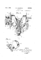
- Figure 1 is a view partly in section and partly in elevation taken through a carburetor embodying this invention
- Figure 2 is a cross section view-taken through Figure 1 onthe plane of the line2-2;
- Figure 3 is an enlarged detail view partlyin elevation and partlyin section illustratingthe relationship'of the-fuel jet to the Venturi;
- Figure 4 is a section view taken through Figure 1 on the plane of the line,4''-4;
- Figure 5 is a' perspe'ctive' view of one of the complementary Venturi forming a members and
- v Figure 6 is a perspective'view of the various I 5 therein.
- the open top of the float chamber 8 is closed by a cover 9 which, carries a valve (not shown) operable by a float 10 to control the flow of liquid fuel into the float chamber from a fuel supply pipe 11.
- the float chamber 8 is communicated through a port 12 leading from its bottom, with a transverse bore 13 which leads to a vertical bore 14 formed in the bottom of the casting 7.
- a needle valve 16 is provided to control the degree of commimication between the bore 12 and the bore 13 and thereby meters the volume of fuel flowing from the float chamber to the vertical bore 14.
- Secured in the vertical bore 14 is a fuel jet 1'7 of novel construction to be later described.
- the fuel jet 1'7 extends upwardly through the center of the hollow casting '1 which, as is best illustrated in Figure 2, comprises a rear wall 18 from which a side wall 19 extends.
- the marginal edge of the side wall 19 is finished so that all portions thereof lie in a plane parallel with the rear wall 18 and has a cover plate 20 fitted thereon.
- the lower portion of the cover plate 20 has a hollow cylindrical extension 21 which forms an air inlet into the lower portion of the chamber defined by the casting 7 and the cover plate 20.
- the conventional butterfly choke" valve 22 is mounted in the air inlet to control the passage of air therethrough.
- the Venturi chamber 23 thus has substantial communication with the air inlet.
- the venturi formed by these movable members is positioned adjacent the upper end of the fuel jet 1'! and is concentric thereto which is in conformity with best practice; and the air passing upwardly therethrough carries the fuel with it to issue from the venturi chamber 23 through a circular opening 28 in the flat top wall 24.
- a hous ing 29 Above and fixed to the top wall 24 is a hous ing 29 through which a vertical bore 30 extends in communication with the opening 28, to form a throttle chamber.
- a conventional throttle valve The complementary movable members 26 and 27 which co-act to form the variable venturi are identical in construction except that they are opposites. As best illustrated in Figure 5 they have a peculiar configuration and are preferably castings having vmounting shafts 33 and 33' respectively fixed thereto, the ends of which project from the opposite ends of the members. The projecting ends of the shafts 33 and 33 are freely joumalled in bearings formed in the rear wall 18 of the casting '1 and the front cover plate 20 in axial alignment with the axes about which the cylindrical walls 25 are concentric.
- the members 26 and 27 are thus rotatable about these axes and to insure their rotation being synchronized, meshed gears 34 are fixed thereto preferably at their ends adjacent the cover plate 20.
- the concentricity of the side walls of the members extends throughout slightly less than 180 degrees and at the opposite ends of the concentric portions there are end extensions 35 and 36 having fiat side walls tangent to the concentric side wallportions, and which, because of the extent of concentricity being less than 180 degrees, are at an angle to each other so that the members have a roughly V shaped appearance from their ends with the bottom of the V rounded.
- the semi-circular groove 3'! in each of the venturi forming members is of uniformly increas- 1'50"" ing depth from a point of smallest depth 38 adjacent'the end extension to the greatest depth at the opposite end portion 36.
- the groove 37 is semi-circular so that the grooves of the two members which register at all times form a true circular bore which provides a venturi of variable cross sectional area.
- the contour of the co-acting Venturi forming members is such that the location of the venturi or point of smallest opening is constant at a predetermined level with respect to the fuel. jet.
- the contour of the co-acting members may be varied if desired so that the location of the venturi travels .be uniform, but varying uniformly-in'the cross sectional diameter of the Venturi opening per degree of rotation; and again, it may be modi- 'fied toprovide a certain Venturi area at any given rotation regardless of the Venturi area at any other position.
- Venturi area is at all times cpntrolled from the changing engine speeds, throttle position, and load conditions and is governed entirely thereby merely by changes in the static pressure at opposite-sides of the 'Venturi members which results from changing engine speeds, adjustment of the throttle opening, or both.
- the spring 40 is mounted in a pocket 41 formed on the cover '20 surrounding the projected end 42 of the shaft 33 mounting the Venturi forming member 26.
- extended shaft end 42 extends into the pocket and is slotted to receive one end of the spring 40.
- the opposite end of the spring is hooked about a pin 43 carried by an adjusting disc 44 which closes the openfront of the pocket 41.
- the disc 44 is held in its position closing the pocket by an arm 45'flxed to the cover 20 by a screw 46 and the peripheral edge of a portion of the disc 44 is serrated as at 47 to be engaged by one end of a small detent spring 48 mounted on, the screw-i6.
- the spring 48 serves to hold the disc 44 inany desired position of adjustment andobviously by turning the disc the tension of the spring 40 may be regulated.
- the spring 40 in the present instance, is a spiral ribbon spring, but may be replaced by any other type of spring suitable for the purpose.
- the tensionof the spring 40 is adjusted so that the Venturi forming members will be held in their normal positions afiording a minimum passage until the variation or difference in static pressure at opposite sides of the Venturi forming members reaches a predetermined degree and as this'differencein static pressure at the opposite sides of the members increased in proportion to the increase in the engine speed, greater throttle opening, or both, the Venturi forming members will be rotated to proportionately increase the Venturi area.
- Venturi members in response to a variation in draught is substantially similar to that described in the aforementioned copending application, but as hereinbefore brought out,.this' invention not only contemplates'a variable venturi for affording the proper control.
- This jet consists of a central tubular stem or stand pipe 49, the lower threaded end 50 of which is secured in the bore 14 to mount the entire jet.
- An enlarged hexagonal flange 51 is formed adjacent the lower end of the stem, and its extreme upper end has its inner periphery chamfered to provide an annular valve seat 52.
- Engageable with this seat 52 is the upper closed end 53' of an external tube or sleeve 54.
- the sleeve 54 has an external shell 55 and at internal depending tubular stem 56, with the outer walls of; the latter spaced substantially from the inner walls of the outer shell.
- the extreme upper end of the internal depending tubular stem is of substantially the diameter of the bore of the stem or stand pipe 49 and immediately beneath the extreme upper end the outside diameter of the internal depending stem 56 is taperingly reduced to form a metering cone 57 which co-acts with the inner peripheral edge of the valve seat 52 as the sleeve 54 is raised and lowered, in a manner to be later described, to afford a varying degree of communication between the stand pipe and the space between the inner stem and outer shell of the sleeve.
- The'outer shell 55 has its extreme lower end provided with a plurality of ,circumferentially spaced vertical slits 58 to form a multiplicity of spring arms 59, and the extreme lower ends of the arms 59 are'directed inwardly to provide an annular abutment 60 the internal diameter of, whichis slightly greater than the diameter of the central stem or stand pipe.
- the central stem or stand pipe has an enlargement 61 providing an abrupt lower shoulder 62 and a tapered upper portion 63; It is thus possible to slip the sleeve 54 over the central stem to assemble these parts,.the spring arms 59 carrying the inturned ends which afford the annularcure the sleeve on the stem as will be readily 313-.
- the. sleeve 54 has a degree of vertical movement on the stand pipe which is governed by the distance between the annular abutment 60 and the abrupt shoulder 62.
- a central fuel outlet orifice 64 through which the fuel is drawn during idling and slow running conditions of the engine, it being understood that the level of the liquid fuel in the: carburetor comes to. a point slightly beneath the orifice 64.
- the outer shell 55 of the vertically movable sleeve 54 has its opposite sides cut away or slotted as at 65 and at its extreme upper end has a plurality of radial apertures 66 so that air is free to enter the space between the outer'sleeve 55 and the main stem or stand pipe through the cut away portions 65 and pass outwardly therefrom through the radial openings 66.
- the operation of the self-regulating jet is briefly as follows: Under idling condition the sleeve 54 and consequently the cone 5'1 are held in their lowest positions by gravity so that the sleeve rests on the valve seat 52 at the upper end of the stand pipe to close the same except for the idling orifice 64 and thus limits the flow of fuel to the amount which will pass through the idling orifice.
- vAir passing through the Venturi minimum opening is of sufiicient velocity to atomize fuel issuing from the idling orifice.
- the resulting suction above the venturi lifts the sleeve 54 and consequently the cone 57 from its seat permitting fuel to discharge from ing to the difference in static pressure by the weights, the first of which is the jet itself and the rest, the plurality of cups which are successively lifted at predetermined intervals as the sleeve raises.
- the carburetor of this invention not only maintains a proper supply of air at all engine speeds, but also regulates the discharge of fuel in accordance with the engine requirements, and thus provides a proper mixture and proper volume of carbureted fuel at all engine speeds.
- the outer sleeve 55 has a ring 69 secured thereto at a slight distance above the cups 68. Embracing the sleeve 55 and engaging the undersurface of this ring is a yoke 70 which is formed on the outer end of the lever 71 fixed to a shaft 72 projected into the interior of the air chamber adjacent the lower end of the jet and journalled in a suitable bearing formed in the side wall of the casting 7. To the extended end of the shaft 72 any. suitable operating lever may be secured which inturn may be actuated from any suitable manual means so that the entire movable elements of the jet may be manu-' ally raised to aiford a maximum flow of fuel. In this manner, closing of the choke valve 22 is obviated and if desired the entire valve may be omitted.
- the carburetor of this invention effects a considerable saving. in the consumption of fuel and to further economize on the fuel consumption;
- the passage 12 leading from the float chamber 8 into the communicating passage 13 may be substantially closed whenever the throttle valve is closed, by a metering pin 73.
- This pin is vertically slidable in a suitable bearing formed in the cover .9 of the fioat chamber and is adapted to be actuated by a lever 74.
- the lever 74 is pivotally mounted-on the throttle housing and has one end -75 lying in the path of a cam 76 fixed'to the shaft 32 of the throttle valve, the cam 75 being of such shape that whenever the throttle valve is opened the metering pin '73 will be elevated to afford maximum communication between the float chamber and the fuel jet.
- the carburetor of this invention has many advantages, principal of whichds the fact that air velocity and the.volume of both the 'air and fuel is automatically regulated in correspondence with the varying engine conditions. It is also observed that the rotation of the Venturi forming members is against the air stream passing therethrough. This tends to dampen sudden movement of the members in response to quick throttle opening and prevents fluttering of the Venturi members.
- the rotation of the Venturi members against the air stream also enables the passage formed thereby to diverge toward the throttle housing so that when the throttle is wide open and the Venturi forming members are in their positions forming a passage of maximum area, straight unbroken diverging walls extend from the venturi to the throttle housing.
- Venturi forming members Another advantage resulting from the particular construction of the Venturi forming members is that when they are in their normal idling positions'a reservoir for carbureted properly mixed fuel is formed-between the movable members and the top. wall 24. Upon sudden opening of the throttle the resulting rotation of the members, positively displaces the fuel mixture collected in this space and forces it into the engine intake manifold to insure quick acceleration.
- a carburetor complementary members co-acting to form a venturi variable in area by movement of said members, means connected with one of the members and responsive to a difference in static pressure at opposite sides thereof to move the members contrary to the direction of air flow to open the venturi, a fuel 'jet adapted to discharge fuel into the venturi,
- a carburetor comprising, a casing having an air inlet end, and an outlet connectable with an engine, complementary members in the casing co-acting to form a passage between the inlet and .outlet ends variable in area by movement of the members, means connected with the members and responsive to a difference in static pressure at the outlet and inlet ends of the casing produced by engine suction to move the members contrary to the direction of air flow to increase "the area of the passage, a fuel jet carried by the casing with its outlet endin the passage afforded by the complementary members, means for conducting fuel to said jet, and a movable member associated with the jet and movable di-'- rectly by the effect of the flow of air through the passage thereon to regulate the flow of fuel from the jet.
- a casing having an inlet .end and an outlet end connectible with an engine
- complementary members co-acting to form a. venturi of variable area, said members being movable to adjust the area of the venturi
- means carried by the complementary members and responsive to differences in static pressure at opposite sides thereof to move the members and adjust the Venturi area said means moving the complementary members contrary 'to the direction of air flow to increase the Venturi opening, a fuel jet having its outlet end within the venturi, and a movable member cooperating with the jet to regulatethe flow of fuel from the jet, said movable member being mechanically independent of the complementary members forming the variable venturi but movable by the flow of air through the venturi and consequently acting in synchronism with the changing of the Venturi area.
- a jet for supplying fuel to the carburetor comprising a tubular stem, a member telescoped over the tubular stem and normally resting by gravity in a position closing the open end of the stem except for a small opening through said member to restrict the flow of fuel to a minimum, said member having a. portion subjected to the flow of air through the carburetor produced by engine suction whereby the member is lifted from its normal position to increase the flow of fuel, and normally inactive means becoming operable upon lifting of said member for adding weight thereto.
- a carburetor in a carburetor the combination of a casing having an inlet end and an outlet end connectible with an engine, a venturi through which air is drawn from the inlet end to the outlet end by suction of the engine, a fuel jet for discharging fuel into the carburetor, a movable element for regulating the flow .of fuel from the jet, said movable element having a portion disposed in the venturi to be lifted by the force of air passing therethrough to increase the flow of fuel from the jet, and means for successively adding weight to the movable element as it is lifted.
- a carburetor the combination of a casing 120 connectible with an engine, a jet in the casing, said jet having an outlet of predetermined area, means connecting the jet with a fuel supply, a movable element associated with the jet normally resting by gravity in a position substantially 125 closing the jet outlet and limiting the flow of fuel therefrom to a minimum, said movable element having a portion located in the air stream through the carburetor produced by engine suction to be lifted thereby as the suction increases, 130 said lifting of the movable element increasing the effective outlet of the jet, and means supported independently of the movable element while the movable element is in its lowermost position and arranged to be picked up by the movable ele- 3 ment to add weight to the movable element as it is lifted.
- a carburetor the combination of a casing connectible with an engine, a jet in the casing, said jet having an outlet of predetermined area, 140 means connecting the jet with a fuel supply, a movable element associated with the jet normally resting by gravity in a position substantially closing the jet outlet and limiting the flow of fuel therefrom to a minimum, said movable element 145 having a portion located in the air stream through the carburetor produced by engine suction to be lifted thereby as the suction increases, said lifting of the movable element increasing the effective ou let of the jet, and means of increasing effectiveness for retarding the lifting of the movable element.
- a jet for a carburetor comprising an upright tubular stem, a valve member associated with the stem and normally resting by gravity in a position limiting the flow of fuel from the tubular stem to a minimum, said valve member being liftable by engine suction to increase the flow of fuel from the stem, and means progressively increasing in effectiveness for retarding the lifting of the valve member.
- a jet for a carburetor comprising an upright tubular stem, a valve member associated with the stem and normally resting by gravity in a position limiting the flow of fuel from the tubular stem to a minimum, said valve member being liftable by engine suction to increase the flow of fuel from the stem, and means supported independently of the valve member while the valve member is in its position of rest and adapted to be picked up by the valve member to add weight to the valve member as 'it is lifted and thereby retard the action of the valve member.
- a'fuel jet for discharging fuel into the carburetor
- a movable element for regulating the flow of fuel from the jet, said movable element having a portion to be lifted by the force of air passing the same to increase the flow of fuel from the jet, and means for successively adding weight to the movable element as it is lifted.
- a fuel jet having a normal discharge capacity to supply the volume of fuel required for idling and slow running speeds, movable elements forming a venturi variable in area about the fuel jet, means responsive to an increase in engine suction for augmenting the discharge capacity of the fuel jet, and means also responsive to an increase in engine suction for moving said movable elements to enlarge the area of the venturi, the direction of movement of said movable elements being opposite to the air flow through the venturi whereby the retarding effect of the air resistance on the movable elements in conjunction with the inertia of the movable elements causes the response of the movable elements to enlarge the venturi area upon an increase in engine suction to lag. behind. of the response of the means for increasing the discharge capacity of the fuel jet.
- a jet comprising a stationary hollow stem connectible with a source of fuel and in which the fuel normally stands to a level beneath the outer open end thereof, a tubular member dipping into the column of fuel within the stem and having an idling orifice at its outer end so that fuel may be drawn through the idling orifice, and means for normally closing the open end of the stem and operable to uncover the same upon an increase in engine suction to enable fuel to be drawn directly therefrom.
- a tubular stationary stem means for supplying fuel to the stem to rise to a normal level a short distance beneath the open upper end of the stem, a movable element associated with the stem to close the open upper end thereof except for a small idling orifice and having a tubular part extending from the orifice down beneath the fuel level in the stem so that engine suction during idling conditions raises fuel to issue from the idling orifice without affecting the fuel level in the stem, engine suction at the movable element and greater than that prevalent during idling lifting the movable element to uncover the upper open end of the stem and subject the fuel therein to 'the effect of suction and thus raise its level above the end of the stem.
- a tubular stationary stem means to supply fuel to a predetermined level therein, means to dip into the fuel and enable a small stream to be raised by engine suction prevalent during idling conditions, and means for closing the tubular stem and operable upon engine suction in excess of that prevalent during idling to uncover the fuel in the tubular stem and enable it to be drawn from the stem.
- a tubular stationary stem means to supply fuel to a predetermined level therein, means to dip into the fuel and enable a small stream to be raised by engine suction prevalent during idling conditions, means for closing the tubular stem and operable upon engine suction in excess of that prevalent during idling to uncover the fuel in the tubular stem and enable it to be drawn from the stem, and means for metering the flow of fuel from the stem.
- a venturi variable in area in accordance with differences in engine suction a fuel jet discharging fuel into the venturi, and means movable with respect to the fuel jet directly by the eifect of changes in the flow of air through the venturi on said means to regulate the flow of fuel from the jet,- whereby the degree of motion of said movable means is synchronized with the variation in area of the venturi.
- a fuel jet having a normal discharge capacity to supply the volume of fuel required for idling and slow running speeds, rotatable elements forming a venturi variable in area and encircling the fuel jet, means responsive to an increase in engine suction for augmenting the discharge capacity of the fuel jet, and means responsive to-a static pressure differential at the opposite ends of the venturi produced by an increase in engine suction to enlarge the area of the venturi, the inertia of said rotatable elements retarding their response to an increase in engine suction, so that the means for increasing the discharge capacity of the fuel jet functions in advance of the enlargement of the Venturi area.
- a carburetor the combination of 8. casing having an inlet end and an outlet end connectible with an engine, a pair of complementary rotatable members in the casing, means'mounting the members for rotation about fixed spaced axes between the inlet and outlet ends of the casing, said members having portions concentric to their axes of rotation in rolling engagement with each other and grooved to provide a passage between the inlet and outlet ends variable in area by rotation of said members, and having extended end portions provided with straight walls tangent to the concentric portions to abut and limit the rotation thereof and providing vanes extending beyond the circumference of the concentric portions sufliciently that pressure exerted thereon by a differential in static pressure at the inlet and outlet ends of the casing produced by engine suction exerts a greater turning moment on the rotatable members than is produced thereon by the flow of fluid through said variable passage, and means connecting the members for simultaneous rotation.
- an adjustable Venturi forming member rotatable about a fixed axis and comprising one unitary body having a portion concentric to said axis with long and short end portions tangent to said concentric portion, said concentric portion and end portions having a continuous groove progressively expanding from the short end portion around the concentric portion and along the long end portion, and said long end portion extending farther from the axis of rotation than any other part of the Venturi forming member so that the effect of pressure resulting from a static pressure differential at opposite sides of the member on said long end portion exerts a greater turning moment on the rotatable Venturi forming member than is produced thereon by any effect of the same static pressure differential on any other portion of said member.
- an adjustable Venturi forming member rotatable about a fixed axis and comprising one unitary body having a portion whose outer wall is concentric to said axis of rotation and an end portion one wall of which is tangent to said concentric wall, there being a continuous groove in said body opening to said concentric and tangent walls and progressively expanding with its large end in said end portion, and said end portion extending a substantial distance beyond the circumference of the concentric wall to provide a vane on which the effect of pressure resulting from a static pressure differential at opposite sides of the member exerts a greater turning moment on the rotatable Venturi forming member than is produced thereon by any effect of the same static pressure differential on any other portion of said member.
- a carburetor for internal combustion e'n gines including a throttle, complementary rotatable members formed to define a venturi variable in area, a fuel -jet within the venturi having a normal discharge capacity to supply the volume of fuel required for idling and slow running speeds, means movable by an air flow of predetermined velocity through the venturi resulting from opening of the throttle for increasing the discharge capacity of the fuel jet, and means responsive to a static pressure differential at opposite ends of the venturi produced by engine suction for turning said Venturi forming members to increase the diameter of the Venturi throat upon acceleration by opening of the throttle, said last named means -lagging in its response behind the response of the means movable to increase the discharge capacity of the jet whereby the diameter of the Venturi throat remains unaltered for a short period of time immediately following the opening of the throttle so that the velocity of the air flow through the venturi is spontaneously increased by the opening of the throttle to actuate the movable means controlling the discharge capacity of the jet and afford a rich mixture to give maximum
Landscapes
- Engineering & Computer Science (AREA)
- Chemical & Material Sciences (AREA)
- Combustion & Propulsion (AREA)
- Mechanical Engineering (AREA)
- General Engineering & Computer Science (AREA)
- Control Of The Air-Fuel Ratio Of Carburetors (AREA)
Description
Dec. 4, 1934. w ARMSTRONG 7 1,982,945
CARBURETbR Filed Jan. 2'7, 1932 3 Sheets-Sheet 1 luvs/Wok M'awr Z57 Amy/m7; B 1 1 hw'emfimu ATTORNEY Dec. 4, 1934.
W. E. ARMSTRONG CARBURETOR Filed Jan. 27, 1932 3 Sheets-Sheet 2 INVEN TOR I M57775! JAM/52 F027;
ATTORNEY Dec. 4, 1934. w. E. ARMSTRONG 1,982,945
CARBURETOR Filed Jan. 27, 19 52 3 Sheets-Sheet 3 IN VEN TOR Br 9M A TTORNEV M r/WE Arm/P1727;
Patented Dec. 4, 1934 NT orrica 'CARBURETOR Werner E. Armstrong, Milwaukee, Wis., assignor to Briggs & Stratton Corporation, Milwaukee,
Wis., a corporation of Delaware Application January 27,
193;, Serial No. 589,116 I 21 Claims. 261-41) This invention relates to certain new and useful improvements in carburetors and refers more particularly to carburetors having a variable Venturi as illustrated in the co-pending applica- ,5 tionof Werner E. Armstrong, Serial No. 464,915, filed June 30, 1930, which matured to Patent 1,927,302 granted Sept. 19, 1933.
In the conventional carburetor in which a fixed Venturi is employed, it is impossible to lo obtain a proper mixture and volume of air and fuel for all engine speeds. The fuel volume requirements of an internal combustion engine are obviously continuously varying in correspondence to the speed of the engine and the load thereon. Consequently, carburetors in which the Venturi opening is fixed can operate with maximum efllciency only at a single condition of engine operation. This shortcoming of conventional carburetors has been recognized for a considerable time and many attempts have been made to correct it; I
The provision of a variable venturi, as in the above mentioned co-pending application, re sulted in a substantial improvement in performance, but even with this improvement, ob-
jectionable operation was still. encountered at certain speeds and particularly slow speed. To a substantial degree this objectionable Op "manifested itself in an uneven -rolling" engine performance at idling speeds, which was caused principally by loading" of the carburetor. The provision of fuel jets of difierent discharge areas and their successive functioning helped to some extent to relieve this poor operating condition, but entailed a complicated construction and because the number of jets practically possible, was limited, abrupt changes in the fuel volume delivered into the carburetor were still to be contended with. I a It is therefore an object of this invention to improve the construction of the carburetor forming the subject matter of the above mentioned eo-pending application and to provide a fuel jet which is self-regulating invcorrespondence' with the variation of the Venturi area. 1 A further object of this invention is to. pro-' vide a .novel fuel jet construction which is variable as to the 'area of its fuel outlet, in proportion to thfiiieed of the engine, and in which the area of the jet opening is varied uniformly and gradually.-
Another object of this invention resides in the provisionof a novel self-regulating fuel jet which I elements of the fuel jetshown separated; and in theirproper'order ofassembly.
is so constructed as to insure complete atomiza tignpf the fuel issuing therefrom.
portions thereof acting as vanes responsive-to And a further object of this invention is to provide means for manuallyactuating the movable element of the fuel jet out of its idling position to its-full running position so as to obviate the necessity for closing the conventional choke valve.
with the above and other objects in view which will appear as the description proceeds, this invention resides in the novel" construction, combination and arrangement of parts substantially as hereinafter described and more particularly defined by the appended claims, it being understood that such changes in the precise embodiment of the hereindisclosed invention may be made as come within the scope of the claims. 'In the accompanying drawings, one completego example of the physical embodiment of this invention is illustrated constructed according to the best mode so far devisedfor the practical application of the principles thereof, and in which:
Figure 1 is a view partly in section and partly in elevation taken through a carburetor embodying this invention; 1 V Figure 2 is a cross section view-taken through Figure 1 onthe plane of the line2-2;
Figure 3 is an enlarged detail view partlyin elevation and partlyin section illustratingthe relationship'of the-fuel jet to the Venturi; Figure 4 is a section view taken through Figure 1 on the plane of the line,4''-4; Y 105 Figure 5 is a' perspe'ctive' view of one of the complementary Venturi forming a members and v Figure 6 is a perspective'view of the various I 5 therein. The open top of the float chamber 8 is closed by a cover 9 which, carries a valve (not shown) operable by a float 10 to control the flow of liquid fuel into the float chamber from a fuel supply pipe 11.
The float chamber 8 is communicated through a port 12 leading from its bottom, with a transverse bore 13 which leads to a vertical bore 14 formed in the bottom of the casting 7. A needle valve 16 is provided to control the degree of commimication between the bore 12 and the bore 13 and thereby meters the volume of fuel flowing from the float chamber to the vertical bore 14. Secured in the vertical bore 14 is a fuel jet 1'7 of novel construction to be later described.
The fuel jet 1'7 extends upwardly through the center of the hollow casting '1 which, as is best illustrated in Figure 2, comprises a rear wall 18 from which a side wall 19 extends. The marginal edge of the side wall 19 is finished so that all portions thereof lie in a plane parallel with the rear wall 18 and has a cover plate 20 fitted thereon. The lower portion of the cover plate 20 has a hollow cylindrical extension 21 which forms an air inlet into the lower portion of the chamber defined by the casting 7 and the cover plate 20. The conventional butterfly choke" valve 22 is mounted in the air inlet to control the passage of air therethrough.
From Figure -2 it is observed that in transverse section the lower portion of the casting 7 conforms to the size and shape of the cylindrical extension 21 of the cover plate 20 and that thecasting portion directly thereabove is enlarged to provide a venturi chamber 23. In transverse section, the venturi chamber resembles two cylinders placed side by side and connected at their tops by thefiat top wall 24 of the casting, the inner surface of which is tangent to opposite cylindrical inner surfaces 25 of the side wall 19. The axes about which the cylindrical inner walls 25 are concentric-are spaced apart a distance less than twice the radius of the'cylindrical walls 25, and are so located with respect, to the axis of the cylindrical extension 21 that the lower portions of the cylindrical walls 25 intersect the inner circular wall of the lower portion of the casting which, as hereinbefore stated, is substantially a projection of the cylindrical extension 21. The Venturi chamber 23 thus has substantial communication with the air inlet. Within the venturi chamber 23 are two complementary movable members 26 and 2'7 which are so formed as to co-act and provide a variable venturi in a manner to be later described. The venturi formed by these movable members is positioned adjacent the upper end of the fuel jet 1'! and is concentric thereto which is in conformity with best practice; and the air passing upwardly therethrough carries the fuel with it to issue from the venturi chamber 23 through a circular opening 28 in the flat top wall 24.
Above and fixed to the top wall 24 is a hous ing 29 through which a vertical bore 30 extends in communication with the opening 28, to form a throttle chamber. A conventional throttle valve ,The complementary movable members 26 and 27 which co-act to form the variable venturi are identical in construction except that they are opposites. As best illustrated in Figure 5 they have a peculiar configuration and are preferably castings having vmounting shafts 33 and 33' respectively fixed thereto, the ends of which project from the opposite ends of the members. The projecting ends of the shafts 33 and 33 are freely joumalled in bearings formed in the rear wall 18 of the casting '1 and the front cover plate 20 in axial alignment with the axes about which the cylindrical walls 25 are concentric.
The members 26 and 27 are thus rotatable about these axes and to insure their rotation being synchronized, meshed gears 34 are fixed thereto preferably at their ends adjacent the cover plate 20.
Returning to the description of the movable members 26 and 2'1, per se, it is observed that the side wall of the major portion of each member is concentric to the axis of its mounting shaft and the radius of this concentric portion is equal'to half the pitch diameter of the gears 34 so that the concentric portions of the side walls just engage and substantially roll on each other as the members rotate.
The concentricity of the side walls of the members extends throughout slightly less than 180 degrees and at the opposite ends of the concentric portions there are end extensions 35 and 36 having fiat side walls tangent to the concentric side wallportions, and which, because of the extent of concentricity being less than 180 degrees, are at an angle to each other so that the members have a roughly V shaped appearance from their ends with the bottom of the V rounded.
The straight walls of the end extensions 35 an 35 being tangent to the concentric side wall portions of the members, abut each other as the members are rotated about their respective axes in opposite directions to limit the rotation thereof.
In Figure 2, the members are shown in the positions with their smaller end extensions 35 in engagement. The other end extensions 36 have their ends curved to conform to the cylindrical walls 25 and lie directly adjacent thereto with but a working clearance therebetween. In view of the fact that the radius on which the cylindrical walls 25 are struck, is greater than one-half the distance between the axes about which the movable members rotate, it follows that the end extensions" 36 of the movable members extend a substantial distance beyond a circle formed as a continuation of the concentric side wall portions of the members. The extension of these ends of the movable members in this rfianner thus results in an unbalanced structure with the extended ends substantially forming vanes adapted upon a difference in static pressure on opposite sides of the venturi members, to move up or down in an arc and simultaneously rotate the Venturi forming members one way or the other.
In view of the fact that the extended ends which provide the vanes lie directly adjacent the circular walls25, and the concentric portions of the members, side walls are in engagement, the only communication between the air supply chamber at the lower portion of the casting which communicates with the air inlet and the upper portion of the casting which connects with the throttle chamber, is through a passageway formed jointly by semi-circular grooves 37 inthe side walls of the movable members.
The semi-circular groove 3'! in each of the venturi forming members is of uniformly increas- 1'50"" ing depth from a point of smallest depth 38 adjacent'the end extension to the greatest depth at the opposite end portion 36. At all positions, however, the groove 37 is semi-circular so that the grooves of the two members which register at all times form a true circular bore which provides a venturi of variable cross sectional area.
It is observed that when the movable members are in their positions illustrated in Figures 1 and 2, with the ends 35 abutting and the area of the passage afforded by the registering grooves is minimum, the entrance to the passage is flared as at 3'7 by a taperedincrease in the depth of the groove in an opposite direction from the point of smallest depth. This oppositely increasing depth of the groove is located entirely within the abutting ends 35. A true venturi is thus afforded which, as hereinbefore stated, is adjacent the discharge end of the fuel jet 1'7 and in conformity with best practice is concentric thereto.
In the present instance, the contour of the co-acting Venturi forming members is such that the location of the venturi or point of smallest opening is constant at a predetermined level with respect to the fuel. jet. However, the contour of the co-acting members may be varied if desired so that the location of the venturi travels .be uniform, but varying uniformly-in'the cross sectional diameter of the Venturi opening per degree of rotation; and again, it may be modi- 'fied toprovide a certain Venturi area at any given rotation regardless of the Venturi area at any other position.
However, in all cases the Venturi area is at all times cpntrolled from the changing engine speeds, throttle position, and load conditions and is governed entirely thereby merely by changes in the static pressure at opposite-sides of the 'Venturi members which results from changing engine speeds, adjustment of the throttle opening, or both.
Under idling conditions with the throttle substantially closed there is obviously a minimum suction created by the engine and hence a mini- .mum degree of depression or partial vacuum above the Venturi forming members.
With thiscondition, the Venturi forming members are held in thir normal positions with the area 'of' the-Venturi opening at aminimum, by-
a light spiral spring 40. The spring 40 is mounted in a pocket 41 formed on the cover '20 surrounding the projected end 42 of the shaft 33 mounting the Venturi forming member 26. The
The disc 44 is held in its position closing the pocket by an arm 45'flxed to the cover 20 by a screw 46 and the peripheral edge of a portion of the disc 44 is serrated as at 47 to be engaged by one end of a small detent spring 48 mounted on, the screw-i6. The spring 48 serves to hold the disc 44 inany desired position of adjustment andobviously by turning the disc the tension of the spring 40 may be regulated.
The spring 40, in the present instance, is a spiral ribbon spring, but may be replaced by any other type of spring suitable for the purpose.
The tensionof the spring 40 is adjusted so that the Venturi forming members will be held in their normal positions afiording a minimum passage until the variation or difference in static pressure at opposite sides of the Venturi forming members reaches a predetermined degree and as this'differencein static pressure at the opposite sides of the members increased in proportion to the increase in the engine speed, greater throttle opening, or both, the Venturi forming members will be rotated to proportionately increase the Venturi area.
The action of the Venturi members in response to a variation in draught is substantially similar to that described in the aforementioned copending application, but as hereinbefore brought out,.this' invention not only contemplates'a variable venturi for affording the proper control.
of air at all engine speeds, but also provides means for varying or regulating the volume of fuel issuing from the jet .in proportion to the air displaced at various speeds of the engine and its requirements. The regulation of the fuel feed is affordedby the'novel jet now about to be described. This jet consists of a central tubular stem or stand pipe 49, the lower threaded end 50 of which is secured in the bore 14 to mount the entire jet. An enlarged hexagonal flange 51 is formed adjacent the lower end of the stem, and its extreme upper end has its inner periphery chamfered to provide an annular valve seat 52. Engageable with this seat 52 is the upper closed end 53' of an external tube or sleeve 54.
The sleeve 54 has an external shell 55 and at internal depending tubular stem 56, with the outer walls of; the latter spaced substantially from the inner walls of the outer shell. The extreme upper end of the internal depending tubular stem is of substantially the diameter of the bore of the stem or stand pipe 49 and immediately beneath the extreme upper end the outside diameter of the internal depending stem 56 is taperingly reduced to form a metering cone 57 which co-acts with the inner peripheral edge of the valve seat 52 as the sleeve 54 is raised and lowered, in a manner to be later described, to afford a varying degree of communication between the stand pipe and the space between the inner stem and outer shell of the sleeve.
At a point spaced above the hexagonal flange 51, the central stem or stand pipe has an enlargement 61 providing an abrupt lower shoulder 62 and a tapered upper portion 63; It is thus possible to slip the sleeve 54 over the central stem to assemble these parts,.the spring arms 59 carrying the inturned ends which afford the annularcure the sleeve on the stem as will be readily 313-.
parent. In this assembled relationship the. sleeve 54 has a degree of vertical movement on the stand pipe which is governed by the distance between the annular abutment 60 and the abrupt shoulder 62.
At the extreme upper end of the sleeve 54 is a central fuel outlet orifice 64 through which the fuel is drawn during idling and slow running conditions of the engine, it being understood that the level of the liquid fuel in the: carburetor comes to. a point slightly beneath the orifice 64. The outer shell 55 of the vertically movable sleeve 54 has its opposite sides cut away or slotted as at 65 and at its extreme upper end has a plurality of radial apertures 66 so that air is free to enter the space between the outer'sleeve 55 and the main stem or stand pipe through the cut away portions 65 and pass outwardly therefrom through the radial openings 66.
Near the lower end of the outer sleeve it is observed that there is an annular shoulder 67 and telescoped over the lower end portion of the outer sleeve is a plurality of inverted cups 68 of increasing size and height. The smallest of these cups which is on the inside, is of a height slightly greater than the distance from the top of the flange 51 to the top of the annular shoulder 67 and the successive cups are similarly of increasing heights. All of i the cups normally rest-on the fiange 51.
Hence, it follows that 'as the sleeve 54 is raised, first one cup and then another is picked up and carried along, the purpose of these cups being to add weight to the sleeve 54 as it is elevated by the increasing suction resulting from an increasing engine speed.
The operation of the self-regulating jet is briefly as follows: Under idling condition the sleeve 54 and consequently the cone 5'1 are held in their lowest positions by gravity so that the sleeve rests on the valve seat 52 at the upper end of the stand pipe to close the same except for the idling orifice 64 and thus limits the flow of fuel to the amount which will pass through the idling orifice. vAir passing through the Venturi minimum opening is of sufiicient velocity to atomize fuel issuing from the idling orifice.
As the throttle is opened and the engine speed increases, the resulting suction above the venturi lifts the sleeve 54 and consequently the cone 57 from its seat permitting fuel to discharge from ing to the difference in static pressure by the weights, the first of which is the jet itself and the rest, the plurality of cups which are successively lifted at predetermined intervals as the sleeve raises.
It is to be noted that during idling conditions when the cone 57. rests on the valve seat 52 to limit the flow of fuel from the jet to the amount during idling andthe fuel contained therein has no effect on the volume of fuel drawn through the idling orifice. 'flius the desired idling condition is assured as the volume of idling fuel is positively limited.
However, as soon as the speed of the engine permits the increased suction to lift the fuel level above the toad the stem or stand pipe so that it discharges into the space between the stand pipe and the sleeve.
It is also observed that when the cone 57 and the inner and outer sleeves associated therewith are lifted, an air trap or pocket is formed above the end of the stem or stand pipe. In this pocket the air traveling upwardly through the space between the stern and outer sleeve eddies and thoroughly turbulates and emulsifies the fuel issuing from the top of the stem, before discharging it through the ports '66 into the main air stream.
From the description thus far it is evident that the carburetor of this invention not only maintains a proper supply of air at all engine speeds, but also regulates the discharge of fuel in accordance with the engine requirements, and thus provides a proper mixture and proper volume of carbureted fuel at all engine speeds.
It is observed that the outer sleeve 55 has a ring 69 secured thereto at a slight distance above the cups 68. Embracing the sleeve 55 and engaging the undersurface of this ring is a yoke 70 which is formed on the outer end of the lever 71 fixed to a shaft 72 projected into the interior of the air chamber adjacent the lower end of the jet and journalled in a suitable bearing formed in the side wall of the casting 7. To the extended end of the shaft 72 any. suitable operating lever may be secured which inturn may be actuated from any suitable manual means so that the entire movable elements of the jet may be manu-' ally raised to aiford a maximum flow of fuel. In this manner, closing of the choke valve 22 is obviated and if desired the entire valve may be omitted.
It has beenfound that the carburetor of this invention effects a considerable saving. in the consumption of fuel and to further economize on the fuel consumption; the passage 12 leading from the float chamber 8 into the communicating passage 13 may be substantially closed whenever the throttle valve is closed, by a metering pin 73. This pin is vertically slidable in a suitable bearing formed in the cover .9 of the fioat chamber and is adapted to be actuated by a lever 74. The lever 74 is pivotally mounted-on the throttle housing and has one end -75 lying in the path of a cam 76 fixed'to the shaft 32 of the throttle valve, the cam 75 being of such shape that whenever the throttle valve is opened the metering pin '73 will be elevated to afford maximum communication between the float chamber and the fuel jet.
From the foregoing. description-taken in connection with the accompanying drawings, it is apparent that the carburetor of this invention has many advantages, principal of whichds the fact that air velocity and the.volume of both the 'air and fuel is automatically regulated in correspondence with the varying engine conditions. It is also observed that the rotation of the Venturi forming members is against the air stream passing therethrough. This tends to dampen sudden movement of the members in response to quick throttle opening and prevents fluttering of the Venturi members.
.5 The fact that the Venturi forming members rotate against the air stream plus their inertia permits a rich starting or accelerating mixture to be drawn '.nto the engine inasmuch as the functioning of the movable Venturi members '10 lags slightly behind the operation of the movable elements of the jet or nozzle.
The rotation of the Venturi members against the air stream also enables the passage formed thereby to diverge toward the throttle housing so that when the throttle is wide open and the Venturi forming members are in their positions forming a passage of maximum area, straight unbroken diverging walls extend from the venturi to the throttle housing.
Another advantage resulting from the particular construction of the Venturi forming members is that when they are in their normal idling positions'a reservoir for carbureted properly mixed fuel is formed-between the movable members and the top. wall 24. Upon sudden opening of the throttle the resulting rotation of the members, positively displaces the fuel mixture collected in this space and forces it into the engine intake manifold to insure quick acceleration.
Acceleration is thus obtained under Venturi conditions ideal for full power without necessitating an acceleration pump. Hence, in obviating the necessity for an acceleration pump, loading, due to unregulated discharge of the pump is also avoided, and fuel deficiency entailed by prolonged acceleration periods resulting in emptying of the pumps is also obviated. All of these fea: tures, which flow naturally from the fact that the response of the Venturi forming members lags slightly behind the operation of the element controlling the capacity of the fuel jet, tend to reduce lubrication dilution.
What I claim as my invention is:
1. In a carburetor, complementary members co-acting to form a venturi variable in area by movement of said members, means connected with one of the members and responsive to a difference in static pressure at opposite sides thereof to move the members contrary to the direction of air flow to open the venturi, a fuel 'jet adapted to discharge fuel into the venturi,
and means directly acted upon by the flowof air through the venturi and responsive to the effect of the air flow thereon for regulating the volume of fuel issuing from the jet.
' 2. A carburetor comprising, a casing having an air inlet end, and an outlet connectable with an engine, complementary members in the casing co-acting to form a passage between the inlet and .outlet ends variable in area by movement of the members, means connected with the members and responsive to a difference in static pressure at the outlet and inlet ends of the casing produced by engine suction to move the members contrary to the direction of air flow to increase "the area of the passage, a fuel jet carried by the casing with its outlet endin the passage afforded by the complementary members, means for conducting fuel to said jet, and a movable member associated with the jet and movable di-'- rectly by the effect of the flow of air through the passage thereon to regulate the flow of fuel from the jet.
3. In a carburetor, a casing having an inlet .end and an outlet end connectible with an engine, complementary members co-acting to form a. venturi of variable area, said members being movable to adjust the area of the venturi, means carried by the complementary members and responsive to differences in static pressure at opposite sides thereof to move the members and adjust the Venturi area said means moving the complementary members contrary 'to the direction of air flow to increase the Venturi opening, a fuel jet having its outlet end within the venturi, and a movable member cooperating with the jet to regulatethe flow of fuel from the jet, said movable member being mechanically independent of the complementary members forming the variable venturi but movable by the flow of air through the venturi and consequently acting in synchronism with the changing of the Venturi area.
4. In combination with a carburetor including a casing connectible with an engine, a jet for supplying fuel to the carburetor, comprising a tubular stem, a member telescoped over the tubular stem and normally resting by gravity in a position closing the open end of the stem except for a small opening through said member to restrict the flow of fuel to a minimum, said member having a. portion subjected to the flow of air through the carburetor produced by engine suction whereby the member is lifted from its normal position to increase the flow of fuel, and normally inactive means becoming operable upon lifting of said member for adding weight thereto.
5. In a carburetor the combination of a casing having an inlet end and an outlet end connectible with an engine, a venturi through which air is drawn from the inlet end to the outlet end by suction of the engine, a fuel jet for discharging fuel into the carburetor, a movable element for regulating the flow .of fuel from the jet, said movable element having a portion disposed in the venturi to be lifted by the force of air passing therethrough to increase the flow of fuel from the jet, and means for successively adding weight to the movable element as it is lifted.
- 6. In a carburetor, the combination of a casing 120 connectible with an engine, a jet in the casing, said jet having an outlet of predetermined area, means connecting the jet with a fuel supply, a movable element associated with the jet normally resting by gravity in a position substantially 125 closing the jet outlet and limiting the flow of fuel therefrom to a minimum, said movable element having a portion located in the air stream through the carburetor produced by engine suction to be lifted thereby as the suction increases, 130 said lifting of the movable element increasing the effective outlet of the jet, and means supported independently of the movable element while the movable element is in its lowermost position and arranged to be picked up by the movable ele- 3 ment to add weight to the movable element as it is lifted. 1
7. In a carburetor, the combination of a casing connectible with an engine, a jet in the casing, said jet having an outlet of predetermined area, 140 means connecting the jet with a fuel supply, a movable element associated with the jet normally resting by gravity in a position substantially closing the jet outlet and limiting the flow of fuel therefrom to a minimum, said movable element 145 having a portion located in the air stream through the carburetor produced by engine suction to be lifted thereby as the suction increases, said lifting of the movable element increasing the effective ou let of the jet, and means of increasing effectiveness for retarding the lifting of the movable element.
8. A jet for a carburetor, comprising an upright tubular stem, a valve member associated with the stem and normally resting by gravity in a position limiting the flow of fuel from the tubular stem to a minimum, said valve member being liftable by engine suction to increase the flow of fuel from the stem, and means progressively increasing in effectiveness for retarding the lifting of the valve member.
9. A jet for a carburetor, comprising an upright tubular stem, a valve member associated with the stem and normally resting by gravity in a position limiting the flow of fuel from the tubular stem to a minimum, said valve member being liftable by engine suction to increase the flow of fuel from the stem, and means supported independently of the valve member while the valve member is in its position of rest and adapted to be picked up by the valve member to add weight to the valve member as 'it is lifted and thereby retard the action of the valve member.
10. In a carburetor, a'fuel jet for discharging fuel into the carburetor, a movable element for regulating the flow of fuel from the jet, said movable element having a portion to be lifted by the force of air passing the same to increase the flow of fuel from the jet, and means for successively adding weight to the movable element as it is lifted.
11. In a carburetor for internal combustion engines, a fuel jet having a normal discharge capacity to supply the volume of fuel required for idling and slow running speeds, movable elements forming a venturi variable in area about the fuel jet, means responsive to an increase in engine suction for augmenting the discharge capacity of the fuel jet, and means also responsive to an increase in engine suction for moving said movable elements to enlarge the area of the venturi, the direction of movement of said movable elements being opposite to the air flow through the venturi whereby the retarding effect of the air resistance on the movable elements in conjunction with the inertia of the movable elements causes the response of the movable elements to enlarge the venturi area upon an increase in engine suction to lag. behind. of the response of the means for increasing the discharge capacity of the fuel jet.
12. In a carburetor for internal combustion engines, a jet comprising a stationary hollow stem connectible with a source of fuel and in which the fuel normally stands to a level beneath the outer open end thereof, a tubular member dipping into the column of fuel within the stem and having an idling orifice at its outer end so that fuel may be drawn through the idling orifice, and means for normally closing the open end of the stem and operable to uncover the same upon an increase in engine suction to enable fuel to be drawn directly therefrom.
13. In a carburetor for internal combustion engines, a tubular stationary stem, means for supplying fuel to the stem to rise to a normal level a short distance beneath the open upper end of the stem, a movable element associated with the stem to close the open upper end thereof except for a small idling orifice and having a tubular part extending from the orifice down beneath the fuel level in the stem so that engine suction during idling conditions raises fuel to issue from the idling orifice without affecting the fuel level in the stem, engine suction at the movable element and greater than that prevalent during idling lifting the movable element to uncover the upper open end of the stem and subject the fuel therein to 'the effect of suction and thus raise its level above the end of the stem.
14. In a carburetor for internal combustion engines, a tubular stationary stem, means to supply fuel to a predetermined level therein, means to dip into the fuel and enable a small stream to be raised by engine suction prevalent during idling conditions, and means for closing the tubular stem and operable upon engine suction in excess of that prevalent during idling to uncover the fuel in the tubular stem and enable it to be drawn from the stem.
15. In a carburetor for internal combustion engines, a tubular stationary stem, means to supply fuel to a predetermined level therein, means to dip into the fuel and enable a small stream to be raised by engine suction prevalent during idling conditions, means for closing the tubular stem and operable upon engine suction in excess of that prevalent during idling to uncover the fuel in the tubular stem and enable it to be drawn from the stem, and means for metering the flow of fuel from the stem.
16. In a carburetor, a venturi variable in area in accordance with differences in engine suction, a fuel jet discharging fuel into the venturi, and means movable with respect to the fuel jet directly by the eifect of changes in the flow of air through the venturi on said means to regulate the flow of fuel from the jet,- whereby the degree of motion of said movable means is synchronized with the variation in area of the venturi.
17. In a carburetor, for internal combustion engines, a fuel jet having a normal discharge capacity to supply the volume of fuel required for idling and slow running speeds, rotatable elements forming a venturi variable in area and encircling the fuel jet, means responsive to an increase in engine suction for augmenting the discharge capacity of the fuel jet, and means responsive to-a static pressure differential at the opposite ends of the venturi produced by an increase in engine suction to enlarge the area of the venturi, the inertia of said rotatable elements retarding their response to an increase in engine suction, so that the means for increasing the discharge capacity of the fuel jet functions in advance of the enlargement of the Venturi area.
18. In a carburetor, the combination of 8. casing having an inlet end and an outlet end connectible with an engine, a pair of complementary rotatable members in the casing, means'mounting the members for rotation about fixed spaced axes between the inlet and outlet ends of the casing, said members having portions concentric to their axes of rotation in rolling engagement with each other and grooved to provide a passage between the inlet and outlet ends variable in area by rotation of said members, and having extended end portions provided with straight walls tangent to the concentric portions to abut and limit the rotation thereof and providing vanes extending beyond the circumference of the concentric portions sufliciently that pressure exerted thereon by a differential in static pressure at the inlet and outlet ends of the casing produced by engine suction exerts a greater turning moment on the rotatable members than is produced thereon by the flow of fluid through said variable passage, and means connecting the members for simultaneous rotation.
19. In a carburetor of the character described,
an adjustable Venturi forming member rotatable about a fixed axis and comprising one unitary body having a portion concentric to said axis with long and short end portions tangent to said concentric portion, said concentric portion and end portions having a continuous groove progressively expanding from the short end portion around the concentric portion and along the long end portion, and said long end portion extending farther from the axis of rotation than any other part of the Venturi forming member so that the effect of pressure resulting from a static pressure differential at opposite sides of the member on said long end portion exerts a greater turning moment on the rotatable Venturi forming member than is produced thereon by any effect of the same static pressure differential on any other portion of said member.
20. In a carburetor of the character described, an adjustable Venturi forming member rotatable about a fixed axis and comprising one unitary body having a portion whose outer wall is concentric to said axis of rotation and an end portion one wall of which is tangent to said concentric wall, there being a continuous groove in said body opening to said concentric and tangent walls and progressively expanding with its large end in said end portion, and said end portion extending a substantial distance beyond the circumference of the concentric wall to provide a vane on which the effect of pressure resulting from a static pressure differential at opposite sides of the member exerts a greater turning moment on the rotatable Venturi forming member than is produced thereon by any effect of the same static pressure differential on any other portion of said member.
21. In a carburetor for internal combustion e'n gines including a throttle, complementary rotatable members formed to define a venturi variable in area, a fuel -jet within the venturi having a normal discharge capacity to supply the volume of fuel required for idling and slow running speeds, means movable by an air flow of predetermined velocity through the venturi resulting from opening of the throttle for increasing the discharge capacity of the fuel jet, and means responsive to a static pressure differential at opposite ends of the venturi produced by engine suction for turning said Venturi forming members to increase the diameter of the Venturi throat upon acceleration by opening of the throttle, said last named means -lagging in its response behind the response of the means movable to increase the discharge capacity of the jet whereby the diameter of the Venturi throat remains unaltered for a short period of time immediately following the opening of the throttle so that the velocity of the air flow through the venturi is spontaneously increased by the opening of the throttle to actuate the movable means controlling the discharge capacity of the jet and afford a rich mixture to give maximum power for acceleration.
WERNER E. ARMSTRONG.
Priority Applications (1)
| Application Number | Priority Date | Filing Date | Title |
|---|---|---|---|
| US589116A US1982945A (en) | 1932-01-27 | 1932-01-27 | Carburetor |
Applications Claiming Priority (1)
| Application Number | Priority Date | Filing Date | Title |
|---|---|---|---|
| US589116A US1982945A (en) | 1932-01-27 | 1932-01-27 | Carburetor |
Publications (1)
| Publication Number | Publication Date |
|---|---|
| US1982945A true US1982945A (en) | 1934-12-04 |
Family
ID=24356660
Family Applications (1)
| Application Number | Title | Priority Date | Filing Date |
|---|---|---|---|
| US589116A Expired - Lifetime US1982945A (en) | 1932-01-27 | 1932-01-27 | Carburetor |
Country Status (1)
| Country | Link |
|---|---|
| US (1) | US1982945A (en) |
Cited By (4)
| Publication number | Priority date | Publication date | Assignee | Title |
|---|---|---|---|---|
| US20110226217A1 (en) * | 2010-03-16 | 2011-09-22 | Briggs & Stratton Corporation | Engine speed control system |
| US8910616B2 (en) | 2011-04-21 | 2014-12-16 | Briggs & Stratton Corporation | Carburetor system for outdoor power equipment |
| US8915231B2 (en) | 2010-03-16 | 2014-12-23 | Briggs & Stratton Corporation | Engine speed control system |
| US9316175B2 (en) | 2010-03-16 | 2016-04-19 | Briggs & Stratton Corporation | Variable venturi and zero droop vacuum assist |
-
1932
- 1932-01-27 US US589116A patent/US1982945A/en not_active Expired - Lifetime
Cited By (6)
| Publication number | Priority date | Publication date | Assignee | Title |
|---|---|---|---|---|
| US20110226217A1 (en) * | 2010-03-16 | 2011-09-22 | Briggs & Stratton Corporation | Engine speed control system |
| US8726882B2 (en) | 2010-03-16 | 2014-05-20 | Briggs & Stratton Corporation | Engine speed control system |
| US8915231B2 (en) | 2010-03-16 | 2014-12-23 | Briggs & Stratton Corporation | Engine speed control system |
| US9316175B2 (en) | 2010-03-16 | 2016-04-19 | Briggs & Stratton Corporation | Variable venturi and zero droop vacuum assist |
| US8910616B2 (en) | 2011-04-21 | 2014-12-16 | Briggs & Stratton Corporation | Carburetor system for outdoor power equipment |
| US9598828B2 (en) | 2011-04-21 | 2017-03-21 | Briggs & Stratton Corporation | Snowthrower including power boost system |
Similar Documents
| Publication | Publication Date | Title |
|---|---|---|
| US4080409A (en) | Variable venturi carburetor | |
| US2105056A (en) | Fuel-gas and air carburetor | |
| US1982945A (en) | Carburetor | |
| US3994998A (en) | Carburetor with self adjusting venturi | |
| US1959907A (en) | Universal type carburetor | |
| US1972686A (en) | Carburetor | |
| US3233878A (en) | Charge forming apparatus | |
| US4174361A (en) | Variable downdraft carburetor | |
| US4207274A (en) | Carburetor | |
| US2315052A (en) | Carburetor | |
| US3281132A (en) | Carburetor | |
| US1932764A (en) | Carburetor | |
| US3963809A (en) | Vacuum controlled fuel metering device | |
| US2182580A (en) | Carburetor | |
| US1924595A (en) | Carburetor | |
| US1379127A (en) | Carbureter | |
| US1061995A (en) | Carbureter. | |
| US1856736A (en) | Charge forming device | |
| US3323504A (en) | Internal combustion engine speed governor | |
| CN106321286B (en) | Carburetor for internal combustion engine | |
| US1886787A (en) | Carburetor for internal combustion engines | |
| US1911135A (en) | Charge forming device | |
| US1411426A (en) | Carburetor | |
| US1865471A (en) | Carburetor | |
| US1966449A (en) | Carburetor |