US1982935A - Collapsible trailer vehicle - Google Patents
Collapsible trailer vehicle Download PDFInfo
- Publication number
- US1982935A US1982935A US516014A US51601431A US1982935A US 1982935 A US1982935 A US 1982935A US 516014 A US516014 A US 516014A US 51601431 A US51601431 A US 51601431A US 1982935 A US1982935 A US 1982935A
- Authority
- US
- United States
- Prior art keywords
- members
- floor
- angle
- trailer
- extending
- Prior art date
- Legal status (The legal status is an assumption and is not a legal conclusion. Google has not performed a legal analysis and makes no representation as to the accuracy of the status listed.)
- Expired - Lifetime
Links
- 235000000396 iron Nutrition 0.000 description 28
- 229910000746 Structural steel Inorganic materials 0.000 description 9
- 230000000717 retained effect Effects 0.000 description 5
- 230000000712 assembly Effects 0.000 description 4
- 238000000429 assembly Methods 0.000 description 4
- 230000000284 resting effect Effects 0.000 description 3
- XEEYBQQBJWHFJM-UHFFFAOYSA-N Iron Chemical compound [Fe] XEEYBQQBJWHFJM-UHFFFAOYSA-N 0.000 description 2
- 125000006850 spacer group Chemical group 0.000 description 2
- 241000282320 Panthera leo Species 0.000 description 1
- 229910000831 Steel Inorganic materials 0.000 description 1
- 229910052742 iron Inorganic materials 0.000 description 1
- 239000002184 metal Substances 0.000 description 1
- 229910052751 metal Inorganic materials 0.000 description 1
- 239000010959 steel Substances 0.000 description 1
Images

Classifications
-
- B—PERFORMING OPERATIONS; TRANSPORTING
- B62—LAND VEHICLES FOR TRAVELLING OTHERWISE THAN ON RAILS
- B62D—MOTOR VEHICLES; TRAILERS
- B62D63/00—Motor vehicles or trailers not otherwise provided for
- B62D63/06—Trailers
- B62D63/061—Foldable, extensible or yielding trailers
Definitions
- My invention relates to improvements'in collapsible trailers for automative vehicles; and the objects of my improvements are, first, to provide a collapsible trailer having a folding axle meme her; second, to provide a collapsible trailenhaving a body with a non-foldable bottom; third, to provide a collapsible trailer having spring hangers fixedly attached to its body member; fourth, to provide a trailer adapted tO'bE. collapsed into a plurality of positions for.
- fifth to provide a trailer capable of being collapsed without removal of any of its component parts from the total connected assembly
- sixth to provide a trailer with end gates adapted to lock its bottom memberin a folded or collapsed position
- seventh to provide a collapsible trailer having a non-collapsing bottom unit
- eighth to provide a trailer with a bottom adapted to be moved and supported uprightly from either of its sides
- ninth to provide a trailer having a draw bar adapted to be used from either end of the trailer
- tenth to provide a trailer having.
- an adjustable tongue member attached to a removable floor; eleventh, to provide a trailer having a foldable axle member comprising resilient leaf members; and, twelfth, to provide a trailer having a yoke shackle member comprising integrally a pair of bearing portions.
- Figure l is a plan elevationof the entirecollapsible trailer vehicle; Fig. 2, 2. side elevation of the entire collapsible trailer vehicle; Fig; 3, an-
- FIG. 4 a front elevation of the tongue assembly; Fig. .5, .a side elevation of a spring shackle; Fig. 6, a front elevation of a spring shackle; Fig. 7, an end .elevation of a spring shackle; Fig. 8, a plan elevation of a spring bracket; Fig. 9, a side elevation of .a spring bracket; Fig. 10, an end elevation of a spring bracket;
- Fig. 11 a side elevation of a spring shackle brack-- plan elevation of the leftrear. corner of .thebody.
- Fig. 16 a plan elevation of a portion of the axle together with aportion of its spring assembled-thereto; Fig. 19, a side elevation of a portion of the axle together with a portion' of its wheel and. spring assembled thereto; Fig. 20, 'a plan elevation of one of the separate end gate hinge brackets; Fig. 21, a side elevation of one of the separate end gate hinge brackets; Fig.
- Fig. 22 a plan e'levation of one of the end gate hinges; Fig. 23, a side elevation of one of the end gate hinges; Fig. 24, a partial sectional view taken onthe line 24-24-., Fig. 1; and Fig. 25, a sectional View of the axle members taken on the line 25125, Fig. 19.
- the body A of my collapsible trailer vehicle comprises a floor B; side members C and D, and end members E and F.
- the floor D may be constructed of theboards .1 which extend transverse- I ly' and are each vsuitablyattached to the angle irons 2 and 3 so as to formafixed unit there- With', theangle irons 2 andZ-lextending longitudinally of the body A and further extending beyond the front of thebody A, the angle irons 2 and 3 forming-a guide forthedraw bar .4.
- the draw bar. 4- is further guided at the forwardlendof the angleirons 2uand 3 by the member.
- the member 37 is extended to and suitab1y attached to the under side of "the floor B and is provided with the eye portions 39.
- the member 37 is provided with a hole '7 which is adapted for, alignment with the series of holes 40 which are located in the horizontal flange of the draw bar 4.
- the bolt 8 is adapted to pass through the hole '7 of the draw bar and through one of the series of holes 40, the seriesof holes 40 thus providing for. extending; the draw bar 4 beyond the forward end of the angle irons 2 and 3 to pro vide for positioning the trailer at the desired distance behind the vehicle to which the trailer is to be attached.
- the draw bar 4 is provided with a hole 9 for attaching to a tractor vehicle.
- the draw bar 4 may extend to the rear of the angle irons 2 and 3 in its minimum extended position beyond the forward ends of the angle irons 2 and 3.
- the floor B may, if desired, be constructed of a plurality or of a single metal member.
- the side members and D are repectively provided with the tubularmembers 12 and '13 which are suitably and fixedly attached to the angle members and 11, the members 12 and 13 being slotted to fit over the vertical side of the angle members 12 and 18' as disclosed in detail in Fig. 24.
- Theangle members 14 and 15 are also respectivelyattach'ed' to the floor B at its forward and rearward. sides orrends;v
- the side members C and D are also respectively provided with the members -16-and 17 which extend longitudinally through the tubular members. 12 and 13, the members 16 and 17 being preferably of round section.
- angle members 10.:and 11 are provided attheir endsww-ith an upturned flange portion 18, as disclosed in Figs. 16-andi 17, the portions 18 being further provided with'flange portions 19 which contact with: the vertical flanges of .the anglemembers 14 and :15; Also the anglev members--14. and 15 are'lprovided' withthe flange portions 20 at. the. ends of:v their vertical flanges for the; purposes hereinafter disclosed.
- endq members'E and F are also respectively provided-with; the" tubular members m ands'22 through whichypassthe members 23 whichare preferably of round section.
- the lower member 24 of the end members E and: F are also suitably and respectively fastened in the tubular members-21 and 220i the end membElISE. and F andiareyfmther contained. within the 'eye 25 .ofithexhinge:members-'26.; The; hingemembers 26,. adjacent the memberBFT are. further provided. with: the eyes' '2fl whichz pivotally engage the. pins 28 which aretsuitably' fastened in the eyes 39 of the' members 3 and 29.
- the member 37 issecurely attached to 'thBTlllldBIi side of the floor B 'andxis so. located; as to engage the sides sot'thehinge members 26; the hinge: members'28 .thus'being located and guided by the member??? the member 37 extending: under and supportingthe: end member- E: Similarly the separate brackets 29; at the endof the floor Bfrom' thefmember 3.7,. are fastened'to the under'sidesof thefloor B andsup port and guide the hinge members 2fianclxthe end member F. the hinge members 26 at the-rear end of the vehicle: being also provided. with eyes 2-7 engaging the pins -28 of the brackets 29. It is tobe noted. that themember 37 and the members-29 will thus aid in maintaining the. endmembers E and F, together with their hingemembers26 in their transverse positions.
- the upper members 32 of the end gate members Eand Fare provided, at their ends, with eyes 33 through which extend the upper members 16 and 17 of the side members C and D, the upper. members '16'and- 17 being retained therein" by the pins 34, spacers 35 being interposed between the eyes 33 and the end tubular members 12 and 13- of the side members C'and' D, said spacers 35 thereby engaging and locating the eyes 33 in their proper upright positions.
- the spring shackle brackets 42 are suitably and respectively fastened to the angle members 10 and 11 and are each provided with a boss 43 through which extends thehole 44.
- the springs 45 are composed of a plurality of leaves, are suitof the spring 45, together with the plate 47 which is adapted to engage the sides of the boss 43 of the spring shack1e-bracket42 and the surface at one. endof the eyes. at the end of the springs 45, the plate being retained in position by suitable fastening members passing through the holes 48 of the U shaped member 46.
- the spring brackets 49 are suitably and respectivelyfastened to the angle members 10 and 11 and'areeach' provided with jaws 50 having holes 51 therethrough.
- the jaws 50 are adapted to engage the eyes at the ends of the spring 45, the eyes-of the spring being retained between the jaws 50 by suitable fastening members passing through the hnleszfiLof the'jaws .50iand through'the eyes of the :spring .45...
- the brackets 52' are provided with the slots 53 into which: the'springs 45 fit, the springs 45 being retainedtherein bythe clamp members 54 which, in turn, are fastenedv by the screws 55.
- Thet-brackets52 are further provided with spindle portions 56 on which are suitably mounted the 'bearingassemblies 57 and 58 on: which". in-turn, revolve-the hubs 59 which support the wheels fio as-disclosed in detail in Fig. 19.
- the hubs 59 are provided with hub caps 61 andrwith suitabledustfelts 62.
- the wheels are suitably-provided wi-th rim means for supporting'the tires 63and 75.
- Thebraokets 52 are further provided-with the studs 64 on which are pivotally mounted the outer ends of the axle members65 and67; the axle members being retained on the studs 64' by the nuts 66.
- the'axle members 65 and 67' are'constructedof flat spring or resilient steel members similar-to'th'eleaves of the spring 45, theaxle -members 65 and 67 being assembled with their flat sidesextending in vertical planes to provide the maximum ability-for supporting the load of the trailer vehicle;
- Theaxl'emember 67 is provided with the bracket 68 which-maybe welded or otherwise suitably fastened to the axle member 67.
- the bracket 68 is previdedwithjaws 69'which engage and pivotally support'the eye portion 70 at the inner end of the a-xlemember'fifi; the eye portion 70 being pivotally: retained between the jaws 69 by the pin 71 and the pin'72i
- the bracket 68 is located at approximately the center'of thetrailer between the tires 63 and '75 and theaxlemember 67 has its inner end 73 extended beyond the bracket 68 so that the inner end 73 maybe maintained parallel with and adjacent the axle member 65 when the trailer vehicle assembly is in its non-collapsed or load carrying position, the inner end 73 of the axle member" 6.7 being maintained in its fixed position adjacent the axle member 65.
- The. clampassembly G comprises the clamp'member 77 which fits over the upper edges of'the'axle members 65 and 67, the clamp member 77 being. provided with the shouldered portion '78, which engages. the axle member 67, and the portion 79 which engages the'axle member 65.
- the hook member 80 engages the lower edges of the axle'members 65 and 67 and is provided with a shouldered portion 81 for engaging the axle member 81.
- the hook member 80 passesthrough the portion 79 and the upper part of the clamp member '77 and is provided with a threaded end which engages the wing nut 82.
- the wing nut82 When it is desired to fold or collapse the trailer, the wing nut82 may be loosened and the clamp assembly G slidably moved off the'inner end .73 of the axle member 67 when the axle members 65 and 67 may be pivotally moved and folded about the pin 71.
- the floor A When it is desired to collapse or fold the trailer assembly, the floor A may be swung upwardly to an upright position, either to the right or left side, Fig. 15 disclosing said floor A as being swung upwardly to the right side.
- the floor A may be swung upwardly from either side, the angle members '14 and 15 of the floor A beingsupported on the angle members and 11 duringthe swinging movement, the angle members 14 and 15 tending to pivotally move on the angle members 10 and 11 until the floor A is in an upright position, as disclosed in Figs. 13, 14, and'15, with the outer end surfaces of the boards 1 and the flange resting on the upper horizontal surface of one of the angle members 10 and 11. It is to be noted that there 1 is no direct pivotal connection between the angle members 14 and 15 and the angle members 10 and 11, the ends of the boards 1 and the angle members 14 and 15 merely contactually sliding on the upper horizontal surface of the angle members 10 and 11 during the swinging movement.
- the floor B When the floor A has been swung upwardly as above described, the floor B will occupy a'vertical position adjacent either one of the side members C and D, the side members C and D always remaining in an upright position on vertical flanges of the angle members 10 and 11.
- the endmembers E and F move with the floor B, the end members E and F always remaining pivotally attached to the floor B.
- the end members E and F When the floor B has been moved to its upright position adjacent one of the side members C or D, the end members E and F are pivotally moved to a position adjacent theouter' surface of the side member selected, as in'Figs'. 13, 14, and 15, where the side member C is dis-- closed as being between the floor'B an'dthe end member F.
- the wing nut 82 may be loosened, the clamp assembly G slidably moved beyond the end '73 of-the axle member 67,.and the axle members 6'7 and .65 moved towards each other to .approximately the positions disclosed in Figs. 13 and 15, the tire 63 and itswheel parts moving towards the tire 75, the wheels and their tires 63 and being concentrically aligned in their folded orcollapsed positions.
- the .axlemember 67 may be moved to an extended position from the axle member 65 which will move the wheels 60 with i-ts'tire' 63 to a position behind the wheel 75, asdisclosed'in Fig.14.
- the floorB together with its end members E and F and its draw bar "mechanism, maybe totally removed. from off the angles 14 and 15 and replaced with its draw bar mechanism. extending 'from the opposite end of the' trailer vehicle. .
- This will prove a'decided advantage when the trailer is constructed with its wheels and axle mechanism toward one end of the trailer instead-of on the center of the trailer as shown in Figs, 1 and 2.
- a floor assembly comprising floor'members, a pair of angle irons extending transversely to the floor members of said floor assembly, said angle irons being suitably attached to said floor members, approximately at their central portions, body side assemblies comprising angle irons at their base for looselysupporting said floor assembly, the angle irons of saidbody side assemblies being provided'at each of their ends with a U section extending at right angles therewith, angle irons secured at each endof said floor assembly, each of said last mentioned angle irons being provided with a flange portion extending between the U section at the" ends of the angle irons of said floor assembly for" guiding said floor assembly when moved from its position on the angle irons of said body side assemblies, and body end assemblies hinged on said floor'assembly and suitably connected with said body side sections.
- a-trailer vehicle the combination of a pair of body side members, each provided with a horizontal flange at its base, the ends of said horizontal flange having an upturned U shaped portion 'and a floor assembly supported on the horizontal flanges of said bodyside members, said floor assembly being provided with angular mem bers at each of its ends, each of the angular members of saidfloor assembly having a flange extending atrightangles to the face of said floor assembly; together with a flange extending between the upturned U shaped portion of said body side members.
- a .trailer'vehicle the combination of body side members,.angleironsflhaving portions extending horizontally from said body-sidemembers, eachof said angle irons having upturned channel portions at each of their ends, and a floorassembly resting on the horizontal portions of the angle irons of said body side members and provided with vertically extending flange members, saidfloor assembly being located longitudinallyinthetrailer vehicle by the vertically extending flanges of said-floor assembly engaging the upturnedqportions ofsaid angle lions.
- a pair of side members each provided with channel shaped-retaining: members at their: ends, a floor normally supported in-a horizontal position on said side members, said floor being maintained, when in a horizontal position, against longitudinalmovement by theedge surfaces of the opposite sides of the channel portions of said channelshaped retaining, members, said floor being adapted to be moved through and moved radially with its-corner portions moving between the open sides: of the channel portion of said channel shaped retaining members on either of said pair of side members to a folded position adjacent the other'of said side members, said floor being maintained, when in its folded position, against longitudinal movement by the surfaces of the closed sides of the channelportions of said'channel ishapedretainingmembers, end members, and mea'ns for folding said endmem-; bers adjacentione of said side members.
- TL-In a .foldable vehicle the combination'of a pair of body sidewmembers, angleironsi-suitably attached to each of said body'side members, said. angle irons each being provided with horizontal flanges havingachannelsection ateachof its ends, a floor member supported on the horizontal flanges of said angle irons, and angle irons suit-- ably attached to opposite sidesof said floor member, each of said last mentioned angle ironsbeing providedwith outwardly extending flange portions'extending between the sidesof the channel, sections of the horizontal fl'anges'of the angle irons of said body side members, said outwardly extending flange portions being adapted for movement betweenthe sides ofsaid'ch-annel sec-- tions to permit saidfloor member to be folded adjacent either of said body side members.
- brackets suitably attached to the horizontally extending flanges of the angle iron m'embersof said body side members; a vehicle chassis suitably connected to said brackets, andv a pair of body side members pivotally connected with said'floor assembly.
- a folding vehicle the combination of a pair of body: members suitably supported in permanent upright positions, each of saidbody members being provided with oppositely disposed and inwardly facing channel sections, and a floor assembly supported in a horizontally extending position onsaid body members when the vehicle is in an unfolded position, said floor assembly being supported on its edge in a vertically extending position adjacent one of said body memberswhen the vehicle is in a folded position, said floor assembly being provided with projecting members extending between the channel sections of said body members when the vehicle is in folded and unfolded positions.
- each of-said body side members being provided with upright members together with members extending transversely through said upright members, the-uppermost of said transversely extending members-extending outwardly from said upright members for a greater distance than the remainder of said transversely extending members, a floor assembly supported on said body side members, a second pair of body side members pivotally supported on said floor assembly, said second pair of body side members being provided with eye portions for fitting around.
- each of said angle members being provided with a horizontal flange connected with a vertical flange located at its outer side, the ends of the horizontal flange being each provided with an upturned portion, said upturned portions being each provided with a relatively short flange ex tending vertically, at the inner side of said upturned portion, and'parallel with said first mentioned vertical flange located at the outer side of.
- each of said angle members means for spacing said body side members, and a floor assembly supported on the horizontal flanges of said angle members, said floor assembly being secured together to extend in a single plane, said floor assembly being provided with flanges extending between and adapted to engage said first mentioned vertical flanges of said anglemembers, said last mentioned flanges of said floor assembly being further adapted to engage said relatively short flange of said upturned portions of said angle members.
- bracket member In a trailer vehicle, the combination of a floor, a bracket member suitably secured to the under side of said floor, said bracket member being fixedly mounted relative to said floor, said bracket member having its outer end extending in a fixed position beyond the edge of said floor, said bracket member being provided with a pivot portion adjacent its inner end and extending transversely relative to said bracket member, a hinge member pivotally mounted on said pivot portion of said bracket member, and a body member pivotally connected to the outer end of said hinge member, said body member being supported on the outer end of said bracket member, extending in a fixed position beyond the edge of said floor when said body member is in its assembled position relative to the floor of the trailer vehicle.
- a pair of upright body side members each provided with an angle member having an upturned channel portion at each of its ends, said upturned portions having the open side of their channels oppositely disposed at the ends of said angle member, and a floor assembly provided with flange portions extending in a vertical plane at the corners thereof, said flange portions extending between the sides of the channels of the upturned portions of said angle members, said floor assembly being thereby adapted to be optionally folded in a vertical plane adjacent either of said pair of upright body side members, said flange portions of said floor assembly operatively moving between the sides of the channels of the upturned portions of said angle members.
- a trailer vehicle the combination of a plurality of floor members, a pair of angle members extending transversely to said floor members, said angle members being secured to said floor members at their central portions, side body members each provided with a flange at their base for loosely supporting said floor members, a pair of angle members secured to said floor members and connecting the ends of each of the first mentioned angle members, and end body members pivot-ally mounted on said floor members.
- a body side member provided with an angle iron at its base, said angle iron being provided with an upturned channel section at each of its ends, and a floor assembly provided with angle irons at its ends, each of said angle irons of said floor assembly being provided with flanges at one of its ends, said flanges of the angle irons of said floor assembly extending substantially in a common plane, said floor assembly being adapted to be supported in an upright position adjacent said body side member and within the upturned channel sections at each end of the angle iron of said body side member, said flanges of said angle irons at the ends of said floor assembly resting on said angle irons of said body side member at points located within the upturned channel sections at each end of the angle iron of said body side member.
Landscapes
- Engineering & Computer Science (AREA)
- Chemical & Material Sciences (AREA)
- Combustion & Propulsion (AREA)
- Transportation (AREA)
- Mechanical Engineering (AREA)
- Body Structure For Vehicles (AREA)
Description
1934- h H. H. STAUGAARD 1,982,935
COLLAPSIBLE TRAILER VEHICLE Filed Feb. 16, 1951 2 Sheets-Sheet 1 a 47; H /i 49 a 4 7- ,9 em 56 INVENTOR I934- Q H. H. STAUGAARD 1,982,935
GOLLAPSIBLE TRAILER VEHICLE Filed Feb. 16, 1951 2 Sheets-Sheet 2 ATTOR Y Patented Dec. 4, 1934 UNITED STATES PATENT. oFFicE 7 1,982,935 COLLAPSIBLE TRAILER vnnroLE Hans H. Staugaard, Detroit, Mich. I Application February 16, 1931, Serial No. 516,014 15 Claims. (01. est-42) My invention relates to improvements'in collapsible trailers for automative vehicles; and the objects of my improvements are, first, to provide a collapsible trailer having a folding axle meme her; second, to providea collapsible trailenhaving a body with a non-foldable bottom; third, to provide a collapsible trailer having spring hangers fixedly attached to its body member; fourth, to provide a trailer adapted tO'bE. collapsed into a plurality of positions for. storage requirements; fifth, to provide a trailer capable of being collapsed without removal of any of its component parts from the total connected assembly; sixth, to provide a trailer with end gates adapted to lock its bottom memberin a folded or collapsed position; seventh, to provide a collapsible trailer having a non-collapsing bottom unit; eighth, to provide a trailer with a bottom adapted to be moved and supported uprightly from either of its sides; ninth, to provide a trailer having a draw bar adapted to be used from either end of the trailer; tenth, to provide a trailer having. an adjustable tongue member attached to a removable floor; eleventh, to provide a trailer having a foldable axle member comprising resilient leaf members; and, twelfth, to provide a trailer having a yoke shackle member comprising integrally a pair of bearing portions. v v
I attain these objects, by the mechanism illustrated in the accompanying drawings, in Which:
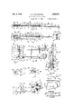
Figure l is a plan elevationof the entirecollapsible trailer vehicle; Fig. 2, 2. side elevation of the entire collapsible trailer vehicle; Fig; 3, an-
end elevation of the rear view of the entirecoh. lapsible trailer vehicle; Fig. 4, a front elevation of the tongue assembly; Fig. .5, .a side elevation of a spring shackle; Fig. 6, a front elevation of a spring shackle; Fig. 7, an end .elevation of a spring shackle; Fig. 8, a plan elevation of a spring bracket; Fig. 9, a side elevation of .a spring bracket; Fig. 10, an end elevation of a spring bracket;
Fig. 11, a side elevation of a spring shackle brack-- plan elevation of the leftrear. corner of .thebody.
portion of the collapsible trailervehicle as disclosed in Fig. 16; Fig. 18, a plan elevation of a portion of the axle together with aportion of its spring assembled-thereto; Fig. 19, a side elevation of a portion of the axle together with a portion' of its wheel and. spring assembled thereto; Fig. 20, 'a plan elevation of one of the separate end gate hinge brackets; Fig. 21, a side elevation of one of the separate end gate hinge brackets; Fig.
22, a plan e'levation of one of the end gate hinges; Fig. 23, a side elevation of one of the end gate hinges; Fig. 24, a partial sectional view taken onthe line 24-24-., Fig. 1; and Fig. 25, a sectional View of the axle members taken on the line 25125, Fig. 19.
Similar numerals refer to similar parts throughout theseveral views. x .1
' The body A of my collapsible trailer vehicle comprises a floor B; side members C and D, and end members E and F. The floor D may be constructed of theboards .1 which extend transverse- I ly' and are each vsuitablyattached to the angle irons 2 and 3 so as to formafixed unit there- With', theangle irons 2 andZ-lextending longitudinally of the body A and further extending beyond the front of thebody A, the angle irons 2 and 3 forming-a guide forthedraw bar .4. The draw bar. 4-is further guided at the forwardlendof the angleirons 2uand 3 by the member. 5 which extends across the bottom flanges of the angle irons 2 and 3 and around' the edges of its'vertical flanges; both ends 'of the member 5 being secured tothe' vertical flanges of the angle irons 2 and 3 by therivets- (if 'The member 3'7 is also attached to the horizontal flangesof the angle irons 2 and 3' by' the rivets 38, said member 3'7'a1so acting as a guide for the draw bar 4. The member 37 is extended to and suitab1y attached to the under side of "the floor B and is provided with the eye portions 39. The member 37 is provided with a hole '7 which is adapted for, alignment with the series of holes 40 which are located in the horizontal flange of the draw bar 4. The bolt 8 is adapted to pass through the hole '7 of the draw bar and through one of the series of holes 40, the seriesof holes 40 thus providing for. extending; the draw bar 4 beyond the forward end of the angle irons 2 and 3 to pro vide for positioning the trailer at the desired distance behind the vehicle to which the trailer is to be attached. The draw bar 4 is provided with a hole 9 for attaching to a tractor vehicle. The draw bar 4 may extend to the rear of the angle irons 2 and 3 in its minimum extended position beyond the forward ends of the angle irons 2 and 3.
It is to be noted that the floor B may, if desired, be constructed of a plurality or of a single metal member.
When the trailer is in its operative position, the lower surface of the boards 1 rest on the angle members 10 and 11. The side members and D are repectively provided with the tubularmembers 12 and '13 which are suitably and fixedly attached to the angle members and 11, the members 12 and 13 being slotted to fit over the vertical side of the angle members 12 and 18' as disclosed in detail in Fig. 24. Theangle members 14 and 15 are also respectivelyattach'ed' to the floor B at its forward and rearward. sides orrends;v
The side members C and D are also respectively provided with the members -16-and 17 which extend longitudinally through the tubular members. 12 and 13, the members 16 and 17 being preferably of round section.
It is to benoted that the angle members 10.:and 11 are provided attheir endsww-ith an upturned flange portion 18, as disclosed in Figs. 16-andi 17, the portions 18 being further provided with'flange portions 19 which contact with: the vertical flanges of .the anglemembers 14 and :15; Also the anglev members--14. and 15 are'lprovided' withthe flange portions 20 at. the. ends of:v their vertical flanges for the; purposes hereinafter disclosed.
The endq members'E and F are also respectively provided-with; the" tubular members m ands'22 through whichypassthe members 23 whichare preferably of round section.
The lower member 24 of the end members E and: F are also suitably and respectively fastened in the tubular members-21 and 220i the end membElISE. and F andiareyfmther contained. within the 'eye 25 .ofithexhinge:members-'26.; The; hingemembers 26,. adjacent the memberBFT are. further provided. with: the eyes' '2fl whichz pivotally engage the. pins 28 which aretsuitably' fastened in the eyes 39 of the' members 3 and 29.
It is. toxbe noted that the member 37 issecurely attached to 'thBTlllldBIi side of the floor B 'andxis so. located; as to engage the sides sot'thehinge members 26; the hinge: members'28 .thus'being located and guided by the member??? the member 37 extending: under and supportingthe: end member- E: Similarly the separate brackets 29; at the endof the floor Bfrom' thefmember 3.7,. are fastened'to the under'sidesof thefloor B andsup port and guide the hinge members 2fianclxthe end member F. the hinge members 26 at the-rear end of the vehicle: being also provided. with eyes 2-7 engaging the pins -28 of the brackets 29. It is tobe noted. that themember 37 and the members-29 will thus aid in maintaining the. endmembers E and F, together with their hingemembers26 in their transverse positions.
The upper members 32 of the end gate members Eand Fare provided, at their ends, with eyes 33 through which extend the upper members 16 and 17 of the side members C and D, the upper. members '16'and- 17 being retained therein" by the pins 34, spacers 35 being interposed between the eyes 33 and the end tubular members 12 and 13- of the side members C'and' D, said spacers 35 thereby engaging and locating the eyes 33 in their proper upright positions.-
The spring shackle brackets 42 are suitably and respectively fastened to the angle members 10 and 11 and are each provided with a boss 43 through which extends thehole 44. The springs 45 are composed of a plurality of leaves, are suitof the spring 45, together with the plate 47 which is adapted to engage the sides of the boss 43 of the spring shack1e-bracket42 and the surface at one. endof the eyes. at the end of the springs 45, the plate being retained in position by suitable fastening members passing through the holes 48 of the U shaped member 46.
The spring brackets 49 are suitably and respectivelyfastened to the angle members 10 and 11 and'areeach' provided with jaws 50 having holes 51 therethrough. The jaws 50 are adapted to engage the eyes at the ends of the spring 45, the eyes-of the spring being retained between the jaws 50 by suitable fastening members passing through the hnleszfiLof the'jaws .50iand through'the eyes of the :spring .45...
The brackets 52' areprovided with the slots 53 into which: the'springs 45 fit, the springs 45 being retainedtherein bythe clamp members 54 which, in turn, are fastenedv by the screws 55. The springs145.maybe-further'suitably restrained from longitudinal movementiin. the slots 53 of the brackets 52; Thet-brackets52 are further provided with spindle portions 56 on which are suitably mounted the 'bearingassemblies 57 and 58 on: which". in-turn, revolve-the hubs 59 which support the wheels fio as-disclosed in detail in Fig. 19. The hubs 59 are provided with hub caps 61 andrwith suitabledustfelts 62. The wheels are suitably-provided wi-th rim means for supporting'the tires 63and 75. Thebraokets 52 are further provided-with the studs 64 on which are pivotally mounted the outer ends of the axle members65 and67; the axle members being retained on the studs 64' by the nuts 66.
It is -"to be'noted that the'axle members 65 and 67' are'constructedof flat spring or resilient steel members similar-to'th'eleaves of the spring 45, theaxle - members 65 and 67 being assembled with their flat sidesextending in vertical planes to provide the maximum ability-for supporting the load of the trailer vehicle;
' Theaxl'emember 67 is provided with the bracket 68 which-maybe welded or otherwise suitably fastened to the axle member 67. The bracket 68 is previdedwithjaws 69'which engage and pivotally support'the eye portion 70 at the inner end of the a-xlemember'fifi; the eye portion 70 being pivotally: retained between the jaws 69 by the pin 71 and the pin'72i The bracket 68 is located at approximately the center'of thetrailer between the tires 63 and '75 and theaxlemember 67 has its inner end 73 extended beyond the bracket 68 so that the inner end 73 maybe maintained parallel with and adjacent the axle member 65 when the trailer vehicle assembly is in its non-collapsed or load carrying position, the inner end 73 of the axle member" 6.7 being maintained in its fixed position adjacent the axle member 65. by the clamp assembly G. The. clampassembly G comprises the clamp'member 77 which fits over the upper edges of'the'axle members 65 and 67, the clamp member 77 being. provided with the shouldered portion '78, which engages. the axle member 67, and the portion 79 which engages the'axle member 65. The hook member 80 engages the lower edges of the axle'members 65 and 67 and is provided with a shouldered portion 81 for engaging the axle member 81. The hook member 80 passesthrough the portion 79 and the upper part of the clamp member '77 and is provided with a threaded end which engages the wing nut 82. As the wingnut 82 is tightened on the hook member 80, the upper portion of the clamp member 77 together with the lower portion of the hook member 80 will .be forced into engagement with the axle members65 and 67 and the portion 79 of the clamp member 77 will be forced into engagement with the vertical face of the axle member 65, thus further forcing the axle members 65 and 67 together.
When it is desired to fold or collapse the trailer, the wing nut82 may be loosened and the clamp assembly G slidably moved off the'inner end .73 of the axle member 67 when the axle members 65 and 67 may be pivotally moved and folded about the pin 71.
When it is desired to collapse or fold the trailer assembly, the floor A may be swung upwardly to an upright position, either to the right or left side, Fig. 15 disclosing said floor A as being swung upwardly to the right side.
It is to be noted that the floor A may be swung upwardly from either side, the angle members '14 and 15 of the floor A beingsupported on the angle members and 11 duringthe swinging movement, the angle members 14 and 15 tending to pivotally move on the angle members 10 and 11 until the floor A is in an upright position, as disclosed in Figs. 13, 14, and'15, with the outer end surfaces of the boards 1 and the flange resting on the upper horizontal surface of one of the angle members 10 and 11. It is to be noted that there 1 is no direct pivotal connection between the angle members 14 and 15 and the angle members 10 and 11, the ends of the boards 1 and the angle members 14 and 15 merely contactually sliding on the upper horizontal surface of the angle members 10 and 11 during the swinging movement.
When the floor A has been swung upwardly as above described, the floor B will occupy a'vertical position adjacent either one of the side members C and D, the side members C and D always remaining in an upright position on vertical flanges of the angle members 10 and 11. During the swinging movement of the floor B, the endmembers E and F move with the floor B, the end members E and F always remaining pivotally attached to the floor B. When the floor B has been moved to its upright position adjacent one of the side members C or D, the end members E and F are pivotally moved to a position adjacent theouter' surface of the side member selected, as in'Figs'. 13, 14, and 15, where the side member C is dis-- closed as being between the floor'B an'dthe end member F.
It is to be noted that when the endmember F is pivotally moved to its position, as disclosed in Figs. 13, 14, and 15, the floor B together with its end members E and F will be supported in an upright position due to the side member D being held between the end members E and F and the floor B. This is accomplished by moving the hinge members 26 upward until the hinge ..members 26 extend parallel with the bottom surface of the boards 1 of the floor B, the end members E and F then being raised sufficiently to allow said end members E and F to be pivotally moved inwardly adjacent the side members C and D.
After the floor B and end members E and F have been folded as in Figs. 13, '14, and 15, the wing nut 82 may be loosened, the clamp assembly G slidably moved beyond the end '73 of-the axle member 67,.and the axle members 6'7 and .65 moved towards each other to .approximately the positions disclosed in Figs. 13 and 15, the tire 63 and itswheel parts moving towards the tire 75, the wheels and their tires 63 and being concentrically aligned in their folded orcollapsed positions. i i
If it is desired to fold the trailer vehicle into a still narrower transverse space, the .axlemember 67 may be moved to an extended position from the axle member 65 which will move the wheels 60 with i-ts'tire' 63 to a position behind the wheel 75, asdisclosed'in Fig.14.
It is to be noted that the floorB, together with its end members E and F and its draw bar "mechanism, maybe totally removed. from off the angles 14 and 15 and replaced with its draw bar mechanism. extending 'from the opposite end of the' trailer vehicle. .This will prove a'decided advantage when the trailer is constructed with its wheels and axle mechanism toward one end of the trailer instead-of on the center of the trailer as shown in Figs, 1 and 2. Due to load conditions inwhich the overhang of the load beyond the trailer bodymay vary,it' may be desired to distribute the load to different advan-. tage which may be accomplished by changing the relative position of the wheels and axle and the front end of the trailer body, thisvbeing accomplished'by changing the floor B end for end on its supports as above described.
"Iclaim:
1. In -a trailer vehicle, the combination of a floor assembly comprising floor'members, a pair of angle irons extending transversely to the floor members of said floor assembly, said angle irons being suitably attached to said floor members, approximately at their central portions, body side assemblies comprising angle irons at their base for looselysupporting said floor assembly, the angle irons of saidbody side assemblies being provided'at each of their ends with a U section extending at right angles therewith, angle irons secured at each endof said floor assembly, each of said last mentioned angle irons being provided with a flange portion extending between the U section at the" ends of the angle irons of said floor assembly for" guiding said floor assembly when moved from its position on the angle irons of said body side assemblies, and body end assemblies hinged on said floor'assembly and suitably connected with said body side sections.
2. In a-trailer vehicle, the combination of a pair of body side members, each provided with a horizontal flange at its base, the ends of said horizontal flange having an upturned U shaped portion 'and a floor assembly supported on the horizontal flanges of said bodyside members, said floor assembly being provided with angular mem bers at each of its ends, each of the angular members of saidfloor assembly having a flange extending atrightangles to the face of said floor assembly; together with a flange extending between the upturned U shaped portion of said body side members.
.3. Ina trailer vehicle, thencombin'ation of a pair of .body side members, each. providedwith' an inwardly extending horizontal flange provided' with channel portionsat each of their ends; and a floor assembly provided with members having an foutwardly extending flange, at each'of its ends,'for engaging the channel portions of the horizontal flanges of said body side memb'ersto permit said floor assembly to be guided to an uprightsupp'orted position on either of said body side; members. I
4'. In a .trailer'vehicle, the combination of body side members,.angleironsflhaving portions extending horizontally from said body-sidemembers, eachof said angle irons having upturned channel portions at each of their ends, and a floorassembly resting on the horizontal portions of the angle irons of said body side members and provided with vertically extending flange members, saidfloor assembly being located longitudinallyinthetrailer vehicle by the vertically extending flanges of said-floor assembly engaging the upturnedqportions ofsaid angle lions.
5. In a trailer vehicle, the combination of a pair of side members each provided with channel shaped-retaining: members at their: ends, a floor normally supported in-a horizontal position on said side members, said floor being maintained, when in a horizontal position, against longitudinalmovement by theedge surfaces of the opposite sides of the channel portions of said channelshaped retaining, members, said floor being adapted to be moved through and moved radially with its-corner portions moving between the open sides: of the channel portion of said channel shaped retaining members on either of said pair of side members to a folded position adjacent the other'of said side members, said floor being maintained, when in its folded position, against longitudinal movement by the surfaces of the closed sides of the channelportions of said'channel ishapedretainingmembers, end members, and mea'ns for folding said endmem-; bers adjacentione of said side members.
6. In. atrai-ler vehicle, the combination of body side: members,a floor: member supported on said body side member, and meansfor connecting said floormemberito both o'f-said body side memhere; said means permittingz saidfloor member to be optionally folded-teen upright position adjacent either of said body side-members, said means :comprising vertically;- extending. channel members: on said body side members. for receiving extensions of'said' member withinthe open sides of the channel members withsuflicient clearance topermitsaid floor1 member to be moved with aradialmovementsf-rom a horizontalposition to antuprigh't position.-
TL-In a .foldable vehicle; the combination'of a pair of body sidewmembers, angleironsi-suitably attached to each of said body'side members, said. angle irons each being provided with horizontal flanges havingachannelsection ateachof its ends, a floor member supported on the horizontal flanges of said angle irons, and angle irons suit-- ably attached to opposite sidesof said floor member, each of said last mentioned angle ironsbeing providedwith outwardly extending flange portions'extending between the sidesof the channel, sections of the horizontal fl'anges'of the angle irons of said body side members, said outwardly extending flange portions being adapted for movement betweenthe sides ofsaid'ch-annel sec-- tions to permit saidfloor member to be folded adjacent either of said body side members.
8. Ina folding vehicle, the'combination of a pair of body'side members each provided with; an angleiron member at its base, said angle iron members each being provided with a horizontally extending flange having upturned and inwardly extending channel sections atits ends, a floor assembly provided with angle iron members at two of its sides, each of said angle. iron members being provided with outwardly: extending flanges located? between the. upturned. and inwardly :extendingr'channel sections of the horizontally extending flanges of the angle iron members of said body side members, brackets suitably attached to the horizontally extending flanges of the angle iron m'embersof said body side members; a vehicle chassis suitably connected to said brackets, andv a pair of body side members pivotally connected with said'floor assembly.
9. In a folding vehicle, the combination of a pair of body: members suitably supported in permanent upright positions, each of saidbody members being provided with oppositely disposed and inwardly facing channel sections, and a floor assembly supported in a horizontally extending position onsaid body members when the vehicle is in an unfolded position, said floor assembly being supported on its edge in a vertically extending position adjacent one of said body memberswhen the vehicle is in a folded position, said floor assembly being provided with projecting members extending between the channel sections of said body members when the vehicle is in folded and unfolded positions.
10.-In a vehicle, the combination of a pair of body side members fixedly supported in upright positions, each of-said body side members being provided with upright members together with members extending transversely through said upright members, the-uppermost of said transversely extending members-extending outwardly from said upright members for a greater distance than the remainder of said transversely extending members, a floor assembly supported on said body side members, a second pair of body side members pivotally supported on said floor assembly, said second pair of body side members being provided with eye portions for fitting around. the ends of the uppermost transversely extending members of said first mentioned pair of body side members, means for securing said eye portions to the uppermost transversely extending members of said first mentioned pair of body side members, and means for spacing said eye portions from the upright members at the ends of said first mentioned pair of body side members.
11. In -a trailer vehicle, the combination of body side members, angle members suitably supported at the bottom of said body side members, each of said angle members being provided with a horizontal flange connected with a vertical flange located at its outer side, the ends of the horizontal flange being each provided with an upturned portion, said upturned portions being each provided with a relatively short flange ex tending vertically, at the inner side of said upturned portion, and'parallel with said first mentioned vertical flange located at the outer side of. each of said angle members, means for spacing said body side members, and a floor assembly supported on the horizontal flanges of said angle members, said floor assembly being secured together to extend in a single plane, said floor assembly being provided with flanges extending between and adapted to engage said first mentioned vertical flanges of said anglemembers, said last mentioned flanges of said floor assembly being further adapted to engage said relatively short flange of said upturned portions of said angle members.
12;: In a trailer vehicle, the combination of a floor, a bracket member suitably secured to the under side of said floor, said bracket member being fixedly mounted relative to said floor, said bracket member having its outer end extending in a fixed position beyond the edge of said floor, said bracket member being provided with a pivot portion adjacent its inner end and extending transversely relative to said bracket member, a hinge member pivotally mounted on said pivot portion of said bracket member, and a body member pivotally connected to the outer end of said hinge member, said body member being supported on the outer end of said bracket member, extending in a fixed position beyond the edge of said floor when said body member is in its assembled position relative to the floor of the trailer vehicle.
13. In a trailer vehicle, the combination of a pair of upright body side members each provided with an angle member having an upturned channel portion at each of its ends, said upturned portions having the open side of their channels oppositely disposed at the ends of said angle member, and a floor assembly provided with flange portions extending in a vertical plane at the corners thereof, said flange portions extending between the sides of the channels of the upturned portions of said angle members, said floor assembly being thereby adapted to be optionally folded in a vertical plane adjacent either of said pair of upright body side members, said flange portions of said floor assembly operatively moving between the sides of the channels of the upturned portions of said angle members.
14. In a trailer vehicle, the combination of a plurality of floor members, a pair of angle members extending transversely to said floor members, said angle members being secured to said floor members at their central portions, side body members each provided with a flange at their base for loosely supporting said floor members, a pair of angle members secured to said floor members and connecting the ends of each of the first mentioned angle members, and end body members pivot-ally mounted on said floor members.
15. In a foldable trailer, the combination of a body side member provided with an angle iron at its base, said angle iron being provided with an upturned channel section at each of its ends, and a floor assembly provided with angle irons at its ends, each of said angle irons of said floor assembly being provided with flanges at one of its ends, said flanges of the angle irons of said floor assembly extending substantially in a common plane, said floor assembly being adapted to be supported in an upright position adjacent said body side member and within the upturned channel sections at each end of the angle iron of said body side member, said flanges of said angle irons at the ends of said floor assembly resting on said angle irons of said body side member at points located within the upturned channel sections at each end of the angle iron of said body side member.
HANS H. STAUGAARD.
Priority Applications (1)
| Application Number | Priority Date | Filing Date | Title |
|---|---|---|---|
| US516014A US1982935A (en) | 1931-02-16 | 1931-02-16 | Collapsible trailer vehicle |
Applications Claiming Priority (1)
| Application Number | Priority Date | Filing Date | Title |
|---|---|---|---|
| US516014A US1982935A (en) | 1931-02-16 | 1931-02-16 | Collapsible trailer vehicle |
Publications (1)
| Publication Number | Publication Date |
|---|---|
| US1982935A true US1982935A (en) | 1934-12-04 |
Family
ID=24053753
Family Applications (1)
| Application Number | Title | Priority Date | Filing Date |
|---|---|---|---|
| US516014A Expired - Lifetime US1982935A (en) | 1931-02-16 | 1931-02-16 | Collapsible trailer vehicle |
Country Status (1)
| Country | Link |
|---|---|
| US (1) | US1982935A (en) |
Cited By (5)
| Publication number | Priority date | Publication date | Assignee | Title |
|---|---|---|---|---|
| US2558153A (en) * | 1948-04-07 | 1951-06-26 | Frank O Peterson | One wheel collapsible trailer |
| US4126324A (en) * | 1976-11-15 | 1978-11-21 | Browning Willard A | Collapsible trailer |
| EP0113154A1 (en) * | 1982-12-31 | 1984-07-11 | Foldi Products Holland B.V. | Collapsible freight car |
| WO2006066346A1 (en) * | 2004-12-23 | 2006-06-29 | Pearce Robert A | Convertible trailer |
| US20150076800A1 (en) * | 2013-09-19 | 2015-03-19 | Randy Davis | Rebuildable utility trailer |
-
1931
- 1931-02-16 US US516014A patent/US1982935A/en not_active Expired - Lifetime
Cited By (8)
| Publication number | Priority date | Publication date | Assignee | Title |
|---|---|---|---|---|
| US2558153A (en) * | 1948-04-07 | 1951-06-26 | Frank O Peterson | One wheel collapsible trailer |
| US4126324A (en) * | 1976-11-15 | 1978-11-21 | Browning Willard A | Collapsible trailer |
| EP0113154A1 (en) * | 1982-12-31 | 1984-07-11 | Foldi Products Holland B.V. | Collapsible freight car |
| US4671530A (en) * | 1982-12-31 | 1987-06-09 | Bussink Engineering B.V. | Collapsible freight car |
| WO2006066346A1 (en) * | 2004-12-23 | 2006-06-29 | Pearce Robert A | Convertible trailer |
| GB2438328A (en) * | 2004-12-23 | 2007-11-21 | Robert Pearce | Convertible trailer |
| GB2438328B (en) * | 2004-12-23 | 2008-12-17 | Robert Pearce | Convertible trailer |
| US20150076800A1 (en) * | 2013-09-19 | 2015-03-19 | Randy Davis | Rebuildable utility trailer |
Similar Documents
| Publication | Publication Date | Title |
|---|---|---|
| US4768806A (en) | Collapsible trailer | |
| US2879072A (en) | Collapsible trailer | |
| US4126324A (en) | Collapsible trailer | |
| US2469506A (en) | Folding wheel trailer | |
| US2080709A (en) | Trailer for automobiles | |
| US1939863A (en) | Boat trailer | |
| US2553959A (en) | Fifth wheel construction | |
| US9108683B2 (en) | Pivoting mud flap assembly | |
| US2777625A (en) | Cargo carrying attachment for automobile | |
| US1982935A (en) | Collapsible trailer vehicle | |
| US20040217578A1 (en) | Collapsible utility trailer | |
| US2556101A (en) | Body attachment for jeeps | |
| US3532236A (en) | Truck camper rig with camper axle dolly | |
| US3310344A (en) | Vehicle mud flap construction | |
| US2110944A (en) | Combination trunk and trailer | |
| US2169648A (en) | Motor vehicle transport | |
| US1925536A (en) | Means for transporting vehicles and the like | |
| JPS625103B2 (en) | ||
| CA2856735C (en) | Pivoting mud flap assembly | |
| US2113448A (en) | Trailer | |
| US2328138A (en) | Collapsible trailer | |
| US2100694A (en) | Skid carrier for motor vehicle transports | |
| US1893532A (en) | Truck body construction | |
| EP0008931A1 (en) | A folding tiltable trailer | |
| US3000523A (en) | Road vehicles |