US1982926A - Operating mechanism for clutches and the like - Google Patents
Operating mechanism for clutches and the like Download PDFInfo
- Publication number
- US1982926A US1982926A US566339A US56633931A US1982926A US 1982926 A US1982926 A US 1982926A US 566339 A US566339 A US 566339A US 56633931 A US56633931 A US 56633931A US 1982926 A US1982926 A US 1982926A
- Authority
- US
- United States
- Prior art keywords
- clutch
- solenoid
- switch
- coil
- contacts
- Prior art date
- Legal status (The legal status is an assumption and is not a legal conclusion. Google has not performed a legal analysis and makes no representation as to the accuracy of the status listed.)
- Expired - Lifetime
Links
- 239000004020 conductor Substances 0.000 description 6
- 230000000694 effects Effects 0.000 description 5
- 238000012423 maintenance Methods 0.000 description 5
- 238000010276 construction Methods 0.000 description 2
- 241000518994 Conta Species 0.000 description 1
- 240000002329 Inga feuillei Species 0.000 description 1
- 238000013459 approach Methods 0.000 description 1
- 238000010586 diagram Methods 0.000 description 1
- 239000002184 metal Substances 0.000 description 1
- 239000011435 rock Substances 0.000 description 1
- 238000000926 separation method Methods 0.000 description 1
Images


Classifications
-
- F—MECHANICAL ENGINEERING; LIGHTING; HEATING; WEAPONS; BLASTING
- F16—ENGINEERING ELEMENTS AND UNITS; GENERAL MEASURES FOR PRODUCING AND MAINTAINING EFFECTIVE FUNCTIONING OF MACHINES OR INSTALLATIONS; THERMAL INSULATION IN GENERAL
- F16H—GEARING
- F16H27/00—Step-by-step mechanisms without freewheel members, e.g. Geneva drives
- F16H27/04—Step-by-step mechanisms without freewheel members, e.g. Geneva drives for converting continuous rotation into a step-by-step rotary movement
- F16H27/10—Step-by-step mechanisms without freewheel members, e.g. Geneva drives for converting continuous rotation into a step-by-step rotary movement obtained by means of disengageable transmission members, combined or not combined with mechanisms according to group F16H27/06 or F16H27/08
-
- F—MECHANICAL ENGINEERING; LIGHTING; HEATING; WEAPONS; BLASTING
- F16—ENGINEERING ELEMENTS AND UNITS; GENERAL MEASURES FOR PRODUCING AND MAINTAINING EFFECTIVE FUNCTIONING OF MACHINES OR INSTALLATIONS; THERMAL INSULATION IN GENERAL
- F16D—COUPLINGS FOR TRANSMITTING ROTATION; CLUTCHES; BRAKES
- F16D67/00—Combinations of couplings and brakes; Combinations of clutches and brakes
- F16D67/02—Clutch-brake combinations
- F16D67/06—Clutch-brake combinations electromagnetically actuated
Definitions
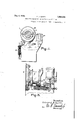
- Fig.1 is a vertical sectional View illustrating the application of .my invention to the intermittent driveof. an actuatingshaft for a shear or thelike.
- Fig 2 isan; end elevation. of the mechanism shown in Fig. 1.
- Fig. 3 is. av large scale sectional view on the line 3-3 of Fig.1.
- Fig.3a isa developed view of the cam members shown inFig. 1.
- Fig; 3b is a fragmentary sectional view on the line, 3b--3b of Fig. 1.
- - 4 is alarge scale sectional view on theline 4---'-4 of Fig.1.
- Fig. 5r is a fragmentary sectional view Fig; 1, illustrating a modified form of the invention.
- FIG. 6 is a, wiring diagram, illustrating the electrical connections by which the operations of the clutching and braking solenoids are secured.
- Figs; Tend 8 are views similar to Fig. 6, showing difierent conditions of the electrical apparatus.
- the driving power in the present instance is shown in the: form of a-continuously rotating gear:2 whichareceives-its rotation'from similar to any suitable source of power, not shown, said driving member 2 being journalledon a stationary quill or sleeve 3, concentric with the driven member 1.
- the constantly rotatinggear 2 has secured to its hub 4 a clutching memberii, providing a series of clutch teeth 6 which are adapted to cooperate with a similar series of clutch teeth 7-on a sliding collar 8.
- the latter is mounted for sliding movement on the projecting end of driven shaft 1, said projecting end being squared/or grooved as shown at 9,'Fig. 3b to prevent relative rotation between said collar Send the shaft 1.
- the collar 8 occupies theposition shownin Fig.
- the mechanism for securing the movement of col1ar:8,'to engage and disengage the clutch is here shown as embodying a slidable member 10. As shown in Figs. 1 and 3, said member 10 is mounted for sliding movement, inga direction parallel to the axis of shaft 1,, in suitable, guide- Ways 11, 11 provided by theframe bracketlZ.
- Themember 10 isconstantly urged to the-left
- the slidable member 10 carries a pin 16,-whereon is journalled a roller 17 received in a circumferential groove Saof clutch collar 8, The sides of said groove are in the form of camsurfaces, 18 and 19, as hereinafter describedyfor-cooperation with roller 17 to obtain the engaging and, disengaging movements of the clutch collar 8.
- The-normalposition of member 10, when the clutch is disengaged, is shown in Fig. 1 as in-.- volving a retraction of saidmember to the right, far enough to dispose a shoulder 20 thereof behind the hooked end 21 of a latch member .22, which-ispivoted as shownrat 23.
- the operation of thelatch 22 or 22, as the case may be, is preferably controlled, according to my invention, by a suitable solenoid, designated at 2'7 in Fig. 1 and also in Fig. 5,the plunger of said solenoid being connected, as shown at 28, to the latch, so that when the solenoid is energized, the latch will be lifted to bring about an operation of the clutch, in the manner'above described.
- a second solenoid 29 to effect, upon itsenergization, the release of a brake 30 which encircles a suitable drum 31 on the driven shaft 1, said brake being normally held contracted on said drum by a spring 32 acting through a lever 33.
- the plunger of solenoid 29 has a link connection 34 with the rock shaft 35,
- FIG. 6 I have shown diagrammatically theclutch solenoid 27 and the brake solenoid 2 9 in association with certain electric ci cuit arm 52.
- the apparatus includes a master switch 38, which, in the open or off position shown by Fig. 6, establishes, by its engagement with a stationary contact 39, a circuit (shown by heavy lines in Fig. 6) which includes the coil 40 of a movable contactor or relay device A, the latter comprising an arm 41 which, by the energization of coil 40, is moved from its broken line position to its full line position, where it engages, as shown, a fixed contact 42.
- a master switch 38 which, in the open or off position shown by Fig. 6, establishes, by its engagement with a stationary contact 39, a circuit (shown by heavy lines in Fig. 6) which includes the coil 40 of a movable contactor or relay device A, the latter comprising an arm 41 which, by the energization of coil 40, is moved from its broken line position to its full line position, where it engages, as shown, a fixed contact 42.
- contactor arm 41 also produces a circuitclosing movement of two bridging contacts 43 and 44, the former of which is operative with respect to a pair of fixed contacts 45, 45, while the latter is operative with respect to a similar pair of fixed contacts 46, 46.
- the arm 41 has an integral arm 41a engaging with the upper end of a rod 43a. to which the bridging contacts 43 and 44 are secure.
- FIG. 6 includes the lead between the coil 40 and the bus lead 37, said coil, the joined connectors 45, 45, another pair of nectors 4'7, 47, joined by a connector 48, the latter being normally in the circuit closing position of Fig. 6, and the lead from the contact 47 to the bus lead 36.
- One of the contacts is connected to one of the contacts 48 as indicated by the dotted line in Fig. 6.
- the connector 48 is associated with the movable member or plunger of the clutch solenoid 27 and is normally in circuit closing position when the solenoid 2'7 is deenergized.
- the master switch establishes electrical connection between two adjacent stationary contacts 49 and 50, the former being connected to the stationary contact 42, and the latter being connected to the coil 51 of a contactor or relay device B, the latter having a movable contact Said arm 52-is electrically connected, as shown at 53, with the movable arm 41 of contactor device A, and the two arms 41 and 52 are electrically connected, as shown at 54, to the side 36 of the supply line.
- a circuit is established, as shown in full-heavy lines, Fig. 7, through the coil 51 of contactor B, this circuit including the conductor 54, contacts 41, 42, 49 and 50, and the coil 51.
- This energization of coil 51 moves the contact arm 52 from the position shown in Fig. 6 to the position shown in Fig. 7, Where the contact 52 engages a stationary contact 55 that is in'circuit, as shown, with the brake solenoid 29.
- the engagement of the two contacts 52 and 55 completes a circuit through said brake solenoid,-'-this circuit including the conductors 54 and 53, the contacts 52 and 55, and the coil of solenoid 29, which is connected at one end to the side 37 of the supply.
- solenoid 29 releases the brake 30 which is normally effective to hold the shaft 1 stationary; coincident with the establishment, as above described, of a circuit through solenoid 29, aholdingicircuit for the contactor 13 2'7 b !v the above described-opening: or the "con- 15 fifitlbllthtd, by *reason' of the fact that t tactsfiwem oil the partionthe'bridgingmember movement of contactor arm ihzo shownin'F-ig. 7 is accompaniedby 'movement"0f two bridging connectors '56 and 5'7, the 'former adapted to bridge a pair of stationarycontacts58,
- a clutch adapted to connect driving and driven members for predetermined movements in unison, a brake normally operative on said driven member, solenoids whose energization procure the release of said brake and the operation of said clutch, a
- a. clutch adapted .to connect driving and driven members for predetermined movements in unison, a brake normally operative on said driven member, solenoids whose energization procure the release of said brake and the operation of said clutch, a switch whose movement to on position procures energization of said solenoids, means responsive to the ensuing operation of said driven member for de-energizing said solenoids, notwithstanding the maintenance of said-switch in its on position, and means operated by the return of said switch to 01f position for restoring the solenoid circuits to conditions that provide for energization thereof on the next movement of said switch to on position.
- a clutch adapted to connect driving and driven members for predetermined movements in unison, a. solenoid whose energization procures the operation of said clutch, a switch whose movement to on position procures energization of said solenoid, and means responsive to the ensuing operation of said driven member for de-energizing said solenoid, notwithstanding the maintenance of said switch in its on position.
- a clutch adapted toconnect driving and driven members for predetermined movements in unison, a solenoid whose energization procures the operation of said clutch, a switch whose movement to on position procures energization of said solenoid, means responsive to the. ensuing operation of said driven member for de-energizing said solenoid, notwithstanding the maintenance of said switch in its on position, and means operated by the return of said switch to its off position for restoring the circuit of said solenoid to a condition which provides for its energization on the next movement of said switch to on position.
- a onerevolution clutch for the intermittent connection of a driven member to a constantly running driving member, a brake for said driven member, a single control device adapted when moved in onedirection by the operator to procure the release of said brake and the engagement of said clutch means for subsequently automatically disengaging the clutch and applying the brake independently of the position of the control device, and means providing for re-engagement of said clutch'only after said control device has been moved in the opposite direction.
- a clutch adapted to connect driving and driven members for predetermined movements in unison, a solenoid-whose energization procures the operation of said clutch, a switch whose move- 12 ment to on position procures energization of said solenoid, automatic control means for deenergizing said solenoid to provide for disengagement of the clutch while the switch is in on position, and means to provide for a second operation of said clutch only after the switch has been moved manually to its off position.
Landscapes
- Engineering & Computer Science (AREA)
- General Engineering & Computer Science (AREA)
- Mechanical Engineering (AREA)
- Physics & Mathematics (AREA)
- Electromagnetism (AREA)
- Hydraulic Clutches, Magnetic Clutches, Fluid Clutches, And Fluid Joints (AREA)
Description
0e94, 1934. E. J. UINN 1,982,926
OPERATING MECHANISM FOR CLUTCHES AND THE LIKE Original Filed April 24, 1930 5 Sheets-Sheet l Fi .l.
. Snvencoa fidwtd Quinn Dec. 4, 1934. J. QUINN 1,982,926
OPERATING MECHANISM FOR CLUTCHES AND THE LIKE Original Filed April 24, 1930 5 Sheets-Sheet, 2 I
F gby hwz Dec. 4, 1934. E'IJ' QUlNN OPERATING MECHANISM FOR CLUTGHES AND THE LIKE Original Filed April 24, 1930 5 Sheets-Sheet 3 invenioR durzflragf. Quinn I flttoane Dec. 4, 1934.
E. J. QUINN 1,982,926
OPERATING MECHANISM FOR CLUTGHES AND THE LIKE Original Filed April 24, 1950 5 Sheets-Sheet 4 .lmreni OR.
(501.11%? Quinn% D 1934- E. J. QUINN 8 ,926
' OPERATING MECHANISM FOR CLUTC HES AND THE LIKE Original Filed April 24, 1930 5 Sheets-Sheet 5 flnlrenioR fdw-ard). Quinn bgmaw Patented Dec. 4, 1934 OPERATING MECHANISM'FOR CLUTCHES AND THE LIKE 7 Edward J- Quinn, Worcester, Mass, assignor to Morgan Construction Company,
Worcester,
Mass, a corporation of Massachusetts .Original application April 24, 1930, Serial No. 446,901. Divided and this application October 1, 1931,, Serial No 566,339
8' Claims. (Cl; 192-144) '-'The present invention relates to operating mechanism for clutches, and is adapted particularly for use with clutches in which the clutchingelementsare intermittently engaged. and disengaged, to procure predetermined angular movementsof adrivenmember, from a constantly rotating driving member. The present application is a division of; my copending application Serial No. 446,901,:filed April 24, v1330.
Theinvention resides-in an automatic electric control. for the clutching devices, arranged in proper interlockingrelation to the application and release of abraking member for theintermittently-driven,.machine. Otherand further objects and advantages of the invention will bemade apparent in the following detailed description thereof, in connection with which reference is had. to the accompanying drawings, wherein Fig.1 is a vertical sectional View illustrating the application of .my invention to the intermittent driveof. an actuatingshaft for a shear or thelike. Fig 2 isan; end elevation. of the mechanism shown in Fig. 1.
Fig. 3 is. av large scale sectional view on the line 3-3 of Fig.1. V
Fig.3a isa developed view of the cam members shown inFig. 1.
. Fig; 3b is a fragmentary sectional view on the line, 3b--3b of Fig. 1.
- 4 is alarge scale sectional view on theline 4---'-4 of Fig.1.
Fig. 5ris a fragmentary sectional view Fig; 1, illustrating a modified form of the invention.
.Fig: 6 is a, wiring diagram, illustrating the electrical connections by which the operations of the clutching and braking solenoids are secured. I
Figs; Tend 8 are views similar to Fig. 6, showing difierent conditions of the electrical apparatus.
'Like reference characters refer to like parts in the different figures.
wForpurposes of. illustration, I have shown the clutching. deviceswhich areoperated by the in- YEl'itlOl'lvflS appliedto the intermittent rotation of a driven shaft 1,-which may be employed, for example, to operate a metal cutting shear ,or the like, not; shown,--it being the function of the clutchito-impart, at intervals, a predetermined angular movement to said shaft, for the purpose ofi procuring a single operation of the shear or other devices, and then to disconnect said shaft from the drivingpower, until another operation is desired. The driving power in the present instanceis shown in the: form of a-continuously rotating gear:2 whichareceives-its rotation'from similar to any suitable source of power, not shown, said driving member 2 being journalledon a stationary quill or sleeve 3, concentric with the driven member 1. The constantly rotatinggear 2 has secured to its hub 4 a clutching memberii, providing a series of clutch teeth 6 which are adapted to cooperate with a similar series of clutch teeth 7-on a sliding collar 8. The latter is mounted for sliding movement on the projecting end of driven shaft 1, said projecting end being squared/or grooved as shown at 9,'Fig. 3b to prevent relative rotation between said collar Send the shaft 1. In the normal non-operative position of the parts, the collar 8 occupies theposition shownin Fig. 1, with its clutch teeth 7 out of engagementwith the rotating teeth. 6 of driving member Z -the driven shaft 1 under these conditions being-stationary. When the collar 8 ismoved to the left, Fig. 1, the clutch teeth 6 and 7 are engaged,.resulting in the rotation ofshaft 1 from the continuouslyrotating gear 2.
The mechanism for securing the movement of col1ar:8,'to engage and disengage the clutch, is here shown as embodying a slidable member 10. As shown in Figs. 1 and 3, said member 10 is mounted for sliding movement, inga direction parallel to the axis of shaft 1,, in suitable, guide- Ways 11, 11 provided by theframe bracketlZ.
Fig. 1, by the expansive action of spring 13, the latter, as here shown, being contained within a lengthwise recess of said member 10, so as to press at one end against said member; at the other end, said spring is seated ona relatively stationary abutment 14, which is carried by a screw 15 adjustablein the frame bracket 12. By means of, said screw, the member 14 is movable inand out, to vary, as desired, 'the expansive force of spring 13,-by which the member 1021s urged to the left'inFigl 1. 1
:The slidable member 10 carries a pin 16,-whereon is journalled a roller 17 received in a circumferential groove Saof clutch collar 8, The sides of said groove are in the form of camsurfaces, 18 and 19, as hereinafter describedyfor-cooperation with roller 17 to obtain the engaging and, disengaging movements of the clutch collar 8. The-normalposition of member 10, when the clutch is disengaged, is shown in Fig. 1 as in-.- volving a retraction of saidmember to the right, far enough to dispose a shoulder 20 thereof behind the hooked end 21 of a latch member .22, which-ispivoted as shownrat 23. When said latch member, 22 islifted clear of the shoulder 20, theexpansive force of spring 1 3-wi1ldrive the member 10 sharply to the left, and the roller 17 being then opposed to the left hand wall of groove 8a, at a point angularly removed from the raised cam surface 18, will shift the collar to the'left, to engage its teeth 7 with the teeth 6 of driving member 2. Thereupon, the rotation of collar 8 and with it the driven shaft 1 is inaugurated; such rotation in due time brings into play against the roller 17 the raised cam surface 18, whereby a retraction of member 10 to its original latched position is obtained. Thereafter, just before the collar 8 and shaft 1 complete a single revolution, the raised cam surface 19 approaches the position shown in Fig. 1, and since the roller 1'7 has been locked by latch 22 against left hand movement, the reaction between roller 1'7 and cam 19 will effect the right hand movement of collar 8 that is necessary to carry the teeth 7 out of engagement with the driver teeth 6.
Referring now to Fig. 5, I have shown a somewhat modified construction of the clutching and unclutching mechanism, as embodied in a slidable collar 8', which provides a pair of cam surfaces 24 and 25, and an operating member 10 which carries, for coaction with the respective cams, the two rollers 24' and 25'. When the latch 22 is raised to release said member 10' for its left hand movement, the engagement of roller 25 with the end of the collar 8', shifts the latter into clutching position,this occurring when the effective surface of cam 25 is angularly displaced from said roller 25'; the ensuing rotation engages cam 25 with said roller 25' and thereby returns the member 10 to its latched position. Thereafter, just before a single revolution of the shaft 1 has been completed, the effective portion of cam 24 arrives opposite the roller 24, and since said roller is locked against left hand movement, a right hand movement of the collar 8 must take place to disengage the clutch teeth 6' and 7. I
The operation of thelatch 22 or 22, as the case may be, is preferably controlled, according to my invention, by a suitable solenoid, designated at 2'7 in Fig. 1 and also in Fig. 5,the plunger of said solenoid being connected, as shown at 28, to the latch, so that when the solenoid is energized, the latch will be lifted to bring about an operation of the clutch, in the manner'above described. Also, as best shown in Fig. 4, I employ a second solenoid 29 to effect, upon itsenergization, the release of a brake 30 which encircles a suitable drum 31 on the driven shaft 1, said brake being normally held contracted on said drum by a spring 32 acting through a lever 33. The plunger of solenoid 29 has a link connection 34 with the rock shaft 35,
from which the lever 33 projects, so that when said solenoid is energized, the shaft 35is rocked in such a direction as to overcome the'force'of spring 32, thereby permitting the brake 30 to expand on drum 31, to release the shaft 1 for free rotation. The control and operation of the solenoids 27 and 29 is effected, according to my invention, by the arrangement of electrical apparatus shown diagrammatically in Figs. 6, '7 and 8, to which reference is now directed for the purpose of setting forth in full detail the manner in which my improved clutch operating mechanism may be electrically actuated and controlled.
Referring to Fig. 6, I have shown diagrammatically theclutch solenoid 27 and the brake solenoid 2 9 in association with certain electric ci cuit arm 52.
hereinafter described, for which the current supplied may be furnished by the and bus leadsv 36 and 37 respectively. The apparatus includesa master switch 38, which, in the open or off position shown by Fig. 6, establishes, by its engagement with a stationary contact 39, a circuit (shown by heavy lines in Fig. 6) which includes the coil 40 of a movable contactor or relay device A, the latter comprising an arm 41 which, by the energization of coil 40, is moved from its broken line position to its full line position, where it engages, as shown, a fixed contact 42. This movement of contactor arm 41 also produces a circuitclosing movement of two bridging contacts 43 and 44, the former of which is operative with respect to a pair of fixed contacts 45, 45, while the latter is operative with respect to a similar pair of fixed contacts 46, 46. As shown in Fig. 6, the arm 41 has an integral arm 41a engaging with the upper end of a rod 43a. to which the bridging contacts 43 and 44 are secure. By virtue of the connection thus made between the two contacts 45, 45, a holding circuit, to maintain the energization of contactor coil 40, notwithstanding a shift of the switch 38 to a different position, is established, and this holding circuit, as shown by the heavy broken lines in Fig. 6, includes the lead between the coil 40 and the bus lead 37, said coil, the joined connectors 45, 45, another pair of nectors 4'7, 47, joined by a connector 48, the latter being normally in the circuit closing position of Fig. 6, and the lead from the contact 47 to the bus lead 36. One of the contacts is connected to one of the contacts 48 as indicated by the dotted line in Fig. 6. The connector 48 is associated with the movable member or plunger of the clutch solenoid 27 and is normally in circuit closing position when the solenoid 2'7 is deenergized.
When the master switch 38 is shifted clockwise,
into the position represented by Fig. 7, eng
ment with stationary contact 39 is broken, thereby opening the direct circuit previously made by said switch through the contactor coil 40; however, the holding circuit above described is at this time undisturbed.- In the position shown by Fig. 7, the master switch establishes electrical connection between two adjacent stationary contacts 49 and 50, the former being connected to the stationary contact 42, and the latter being connected to the coil 51 of a contactor or relay device B, the latter having a movable contact Said arm 52-is electrically connected, as shown at 53, with the movable arm 41 of contactor device A, and the two arms 41 and 52 are electrically connected, as shown at 54, to the side 36 of the supply line. In consequence of connecting the contacts 49 and 50 by the switch 38, as shown in Fig. 7, a circuit is established, as shown in full-heavy lines, Fig. 7, through the coil 51 of contactor B, this circuit including the conductor 54, contacts 41, 42, 49 and 50, and the coil 51. This energization of coil 51 moves the contact arm 52 from the position shown in Fig. 6 to the position shown in Fig. 7, Where the contact 52 engages a stationary contact 55 that is in'circuit, as shown, with the brake solenoid 29. The engagement of the two contacts 52 and 55 completes a circuit through said brake solenoid,-'-this circuit including the conductors 54 and 53, the contacts 52 and 55, and the coil of solenoid 29, which is connected at one end to the side 37 of the supply. The energization of solenoid 29 releases the brake 30 which is normally effective to hold the shaft 1 stationary; coincident with the establishment, as above described, of a circuit through solenoid 29, aholdingicircuit for the contactor 13 2'7 b !v the above described-opening: or the "con- 15 fifitlbllthtd, by *reason' of the fact that t tactsfiwem oil the partionthe'bridgingmember movement of contactor arm ihzo shownin'F-ig. 7 is accompaniedby 'movement"0f two bridging connectors '56 and 5'7, the 'former adapted to bridge a pair of stationarycontacts58,
58*, and the latter adapted to bridge a pair of " stationary contacts 59, 59. The connectors 56 and 57 are mounted on a-rod'56a, the upper end of'which engages an arm 52a integral with thearm 52. *One'otthecontacts 59 is connected by a conductor '60 tothecoil 51, and the other contact 59"is connected-by a conduc'tor61 to a suitable limit switch 62. Thus; asshown by "the heavy-broken lines in Fig. 7, a holding circuit will be'established through the contactor coil 51 if the switch 62 "closed; :said circuit including switch 62-, conductor 61; contacts 59, -59,- cn'nec'tor '7, conductor 60, and coil 51. 1
. The above described ener'gization "of ''coil 51 to' move the'contact arm 52, also produoes the bridging of contacts 58," 58 bythe connector 56, and this establishes another electric circuit/which includes a coil 63 associated with a third contactor'or" relay device C,- -sa-idcircuit, 'as'snown in Fig. '7, being "completed through "'the' pa'irs 'of bridged contacts 58, 58 and 46, '46which are connected by a conductor '64. The contactor device C provides a movable contact arm 65,which*shifts from'thepositionshown in" 6 to the position shown'in Fig. 7. Wheri the coil 63 is energized, this-movement engages arm '65 with a stationary contact '66, so that an electrical circuit,-'as shown Lby'arrows inFig. '7, is established through the clutch solenoid 2'7, this 7 circuit including a 'pair of contacts 6'7; 67 which are normally bridged by a'"connector 68, in the same" fashion as the associated contacts 47, 4'7" are 1 nornially bridged by the associated connector 48, said connector 68, as well as the connector 48;be'ing associated with the plunger of *the solenoid 2'7 formovement therewith. When this 'e'nergization of *solenoid 27- occurs, the latch 22 (or-22')'*is raisedto release the'member '10 for {thereby engaging the clutch in the manner above described. Since the brake summon-294s: energized at the time of the bridgingof the "'c'ontacts58, 58 which-control the relay device C, the 5 latter operating to complete the circuit through the clutch' solenoid' 2'7 the clutch is not energized until after the bra-1x630 on the driven'shaftl has"been'releasemalthough the engagement of the clutch-occurs-a' relatively short time after the release of the brake as determinedby the setting "of the relay device 63. The left hand movement of collar 8 engages a surface 69 thereof with a roller '70 which, as shown in Fig. 2, is carried by an arm '71 pivoted at '72. Through suitable linkage '73, the movement of arm 71 is communicated to the switch 62 to close the same, thus establishing the holding circuit above described for the coil 51 of contactor or relay device B. 1
Immediately upon the energization of the clutch solenoid 27, as above described, the cylinder of said solenoid moves downwardly, and there occurs an opening movement of the two normally closed connectors 48 and 68, which are connected to the plunger, from the position shown in Fig. '7 to the position shown in Fig. 8. The effect of this movement, on the part of the connector 68, is to break the primary circuit, above described, through the solenoid coil 2'7; thereafter, the only current flow through said coil 27 must pass through the relatively \high resistance device '74, which is cut into series with said coil a l All noid energization :is to. break the' holding circuit shown in FigF6 fon the 'coil' 40 of contactor or relay device A; as a result of this, the conta'ct' arm 41 returns; as' shown in 8, to'normal positionywhereuponthe bridging members "43 and '44 are moved to'open the respective pairs of cont'aets 45, 45 ahd 46g46. Theopeningof the cont'acts 46g'46' breaks the' circuit shown in" Fig. '7 throughthe coil-'63 of "contactororrelay device C ;-:-this in' "turn allows the contact arm to separate 'f-rom the contact '66; thereby completely" deen'erg izingi the 'clutch solenoid 27. When. this occurs, the" bridg1ngmembers'48' and 68 return to their normalclosing" positions with respect to the contacts'4'7, A'Fand 6'7, 67, tespectively, but there is -no "reestablishment' atithis time of any holding circuit through the coilAOpbecause the a bridging member: 43 .is not 1 hi engagement with the contacts 45:45.
These last-described operations, taking place whi-le the master switch? 38:- still remains in the position-shown in Fig. '7; res'ulttfinally, as-shown in Fig-5' 8; the deenergization "of the contactor or' 'reiay devices A1and C; as' well as of the clutch solenoid 2'7f after the latter I has secured the release" of the clutch operating mem'ber '10 (or 10) The only coil that remains energized is thebrake solenoid "'coil- 29", this holding the brake BO inoperative while the d'esired revolution of the driven member 1 istaking place. That is' to=-'say,al though the separation of the contacts 41 and 42 in :the' circuit of "coil 51 has already takenplace, the holding circuit'for the device '3 :is still maintained through said coil, because'the switch 62"is still closed: consequently, 'the contact I arm 52 is maintained "in" engagement with the contact 55, as shown in Fig. 8, and the brake solenoid 29'is thus maintained'in an operative condition for the" duration of driving ofi'member 1.
Howeverg'vvhen the collar 8 (or 8) 'shifts to the right in the manner previously described';=to disengage the clutchythe operating arm '71 of. -switch 62fis'soim'oved by surface 69 :as to open said switch, whereby the coil 51 is deenergized; this resulted 'coursepinthe return of contact arm: 52 from the position *shown'in' Fig: 8'to the "position shown in Fig. .6; inconsequence of which the circuit of the brakersolenoid' 29 -isbroken, causing the brake 30 to be appliedito the" drivenshaftl justas the latter completes' its full revolution. I'hus, notwithstanding the maintenance of the master 'switch 38 in the on position, as shown in Figs. 7 and 8, there is no repetition of the clutching operation which has been inaugurated by said master switch, because the completion of the cycle of operations above described automatically re-establishes the conditions illustrated in Fig. 6. In other words, it is impossible for another clutching operation to occur, except as the operator may set out deliberately to inaugurate such operation; to do this, the operator must first return the master switch 38 to the off position (Figs. 1 and 6), and then, when he desires the operation to occur, shift said master switch to the on position (Fig. '7).
I claim,
1. In mechanism of the class described, a clutch adapted to connect driving and driven members for predetermined movements in unison, a brake normally operative on said driven member, solenoids whose energization procure the release of said brake and the operation of said clutch, a
switch whose movement to on positionprocures energizationof said solenoids, and means responsive to the ensuing operation of said driven member for de-energizing said solenoids, notwithstanding the maintenance of said switch in its on position.
2. In mechanism of the class described, a. clutch adapted .to connect driving and driven members for predetermined movements in unison, a brake normally operative on said driven member, solenoids whose energization procure the release of said brake and the operation of said clutch, a switch whose movement to on position procures energization of said solenoids, means responsive to the ensuing operation of said driven member for de-energizing said solenoids, notwithstanding the maintenance of said-switch in its on position, and means operated by the return of said switch to 01f position for restoring the solenoid circuits to conditions that provide for energization thereof on the next movement of said switch to on position.
3; In mechanism of the class described, a clutch adapted to connect driving and driven members for predetermined movements in unison, a. solenoid whose energization procures the operation of said clutch, a switch whose movement to on position procures energization of said solenoid, and means responsive to the ensuing operation of said driven member for de-energizing said solenoid, notwithstanding the maintenance of said switch in its on position.
4. In mechanism of the class described, a clutch adapted toconnect driving and driven members for predetermined movements in unison, a solenoid whose energization procures the operation of said clutch, a switch whose movement to on position procures energization of said solenoid, means responsive to the. ensuing operation of said driven member for de-energizing said solenoid, notwithstanding the maintenance of said switch in its on position, and means operated by the return of said switch to its off position for restoring the circuit of said solenoid to a condition which provides for its energization on the next movement of said switch to on position.
5. In mechanism of the class described, the combination with a constantly running driving member and an intermittently operated driven member, of a clutchoperable to effect the connection and disconnection of said members, a control device movable in one direction by the operator to procure shifting of said clutch from clutch for preventing a subsequent shift of the latter to operative position until said control device is'returned by the operator to its original position.
6. In mechanism of the class described, the combination with a constantly rumiing driving member and an intermittently operated driven member, of a clutch operable to effect the connection and disconnection ,of said members, a control device movable in one direction by the operator to procure shifting of said clutch from inoperative to operative position, for the connection of said members, means responsive to a predetermined rotation in unison of said members for shifting said clutch in the other direction to disconnect said members, and means brought into action by said last-mentioned shift of said clutch for preventing a subsequent connection of said members thereby until after said control device has been moved by the operator in the opposite direction.
7. In mechanism of the class described, a onerevolution clutch for the intermittent connection of a driven member to a constantly running driving member, a brake for said driven member, a single control device adapted when moved in onedirection by the operator to procure the release of said brake and the engagement of said clutch means for subsequently automatically disengaging the clutch and applying the brake independently of the position of the control device, and means providing for re-engagement of said clutch'only after said control device has been moved in the opposite direction.
8. In mechanism of the class described, a clutch adapted to connect driving and driven members for predetermined movements in unison, a solenoid-whose energization procures the operation of said clutch, a switch whose move- 12 ment to on position procures energization of said solenoid, automatic control means for deenergizing said solenoid to provide for disengagement of the clutch while the switch is in on position, and means to provide for a second operation of said clutch only after the switch has been moved manually to its off position.
EDWARD J. QUINN.
Priority Applications (1)
| Application Number | Priority Date | Filing Date | Title |
|---|---|---|---|
| US566339A US1982926A (en) | 1930-04-24 | 1931-10-01 | Operating mechanism for clutches and the like |
Applications Claiming Priority (2)
| Application Number | Priority Date | Filing Date | Title |
|---|---|---|---|
| US446901A US1982925A (en) | 1930-04-24 | 1930-04-24 | Clutch operating mechanism |
| US566339A US1982926A (en) | 1930-04-24 | 1931-10-01 | Operating mechanism for clutches and the like |
Publications (1)
| Publication Number | Publication Date |
|---|---|
| US1982926A true US1982926A (en) | 1934-12-04 |
Family
ID=27034786
Family Applications (1)
| Application Number | Title | Priority Date | Filing Date |
|---|---|---|---|
| US566339A Expired - Lifetime US1982926A (en) | 1930-04-24 | 1931-10-01 | Operating mechanism for clutches and the like |
Country Status (1)
| Country | Link |
|---|---|
| US (1) | US1982926A (en) |
-
1931
- 1931-10-01 US US566339A patent/US1982926A/en not_active Expired - Lifetime
Similar Documents
| Publication | Publication Date | Title |
|---|---|---|
| US1993413A (en) | Electric control method and means for power operated machinery | |
| US1982926A (en) | Operating mechanism for clutches and the like | |
| US1385369A (en) | Control device for automatic machines | |
| US2907434A (en) | Means for arresting the rotation of operating spindles of multi-spindle automatic lathes | |
| US2259574A (en) | Selective control system for power driven machine tools | |
| US2706544A (en) | Machine tool drive | |
| US2091449A (en) | Frictionally synchronized positive drive clutch | |
| US1606308A (en) | Pipe-cutting mechanism | |
| US3053364A (en) | Electromagnetic claw clutches | |
| US799720A (en) | Electromagnetic clutch. | |
| US1744228A (en) | Control system | |
| US3196711A (en) | Machine tool transmission arrangement | |
| US2465332A (en) | Reversing switch control of press machine motors | |
| US1121786A (en) | Motor-controller. | |
| US1982925A (en) | Clutch operating mechanism | |
| US1405640A (en) | Electrically-controlled transmission | |
| US1686584A (en) | Clutch | |
| US2155373A (en) | Control system | |
| US1357384A (en) | Controller for motor-driven machines | |
| US823085A (en) | Clutch-operating mechanism. | |
| US2830686A (en) | Safety device and system | |
| US1472844A (en) | Power-transmitting mechanism | |
| US1264378A (en) | Controlling system. | |
| US1538824A (en) | Apparatus for automatic speed control of electric motors | |
| GB487061A (en) | A device for automatically stopping wire-drawing machines in case of rupture of the wire |