US1982917A - Dispensing apparatus - Google Patents
Dispensing apparatus Download PDFInfo
- Publication number
- US1982917A US1982917A US641460A US64146032A US1982917A US 1982917 A US1982917 A US 1982917A US 641460 A US641460 A US 641460A US 64146032 A US64146032 A US 64146032A US 1982917 A US1982917 A US 1982917A
- Authority
- US
- United States
- Prior art keywords
- container
- measuring device
- ring
- cylinder
- coffee
- Prior art date
- Legal status (The legal status is an assumption and is not a legal conclusion. Google has not performed a legal analysis and makes no representation as to the accuracy of the status listed.)
- Expired - Lifetime
Links
Images

Classifications
-
- G—PHYSICS
- G01—MEASURING; TESTING
- G01F—MEASURING VOLUME, VOLUME FLOW, MASS FLOW OR LIQUID LEVEL; METERING BY VOLUME
- G01F11/00—Apparatus requiring external operation adapted at each repeated and identical operation to measure and separate a predetermined volume of fluid or fluent solid material from a supply or container, without regard to weight, and to deliver it
- G01F11/10—Apparatus requiring external operation adapted at each repeated and identical operation to measure and separate a predetermined volume of fluid or fluent solid material from a supply or container, without regard to weight, and to deliver it with measuring chambers moved during operation
- G01F11/12—Apparatus requiring external operation adapted at each repeated and identical operation to measure and separate a predetermined volume of fluid or fluent solid material from a supply or container, without regard to weight, and to deliver it with measuring chambers moved during operation of the valve type, i.e. the separating being effected by fluid-tight or powder-tight movements
- G01F11/20—Apparatus requiring external operation adapted at each repeated and identical operation to measure and separate a predetermined volume of fluid or fluent solid material from a supply or container, without regard to weight, and to deliver it with measuring chambers moved during operation of the valve type, i.e. the separating being effected by fluid-tight or powder-tight movements wherein the measuring chamber rotates or oscillates
- G01F11/24—Apparatus requiring external operation adapted at each repeated and identical operation to measure and separate a predetermined volume of fluid or fluent solid material from a supply or container, without regard to weight, and to deliver it with measuring chambers moved during operation of the valve type, i.e. the separating being effected by fluid-tight or powder-tight movements wherein the measuring chamber rotates or oscillates for fluent solid material
Definitions
- the bean to the retailers who, in turn, grind it to the order of their customers and put it up in paper bags as each sale is irnade.
- Another practice commonly 'f'ollowed is to grind the coffee at the roasting plant and to put up measured quantitiesin tin containers or cans which are tightly sealed so as to preserve the freshness and laroma of the coffee.
- the coffee is sealed under a vacuum or in an atmosphere of ⁇ an inert gas, such as nitrogen, carbon dioxide, or the like.
- an inert gas such as nitrogen, carbon dioxide, or the like.
- the producers and distributorsthus take much care to deliver 'thecofiee to the lretail purchaser in a fresh condition. Their control over it, however, ends ⁇ when the sale has been made Vand the goods are delivered.
- The'ihousewife or maid usually places a new supply of coffee ina jar lor similar container'and she takes a suitable 'quantityfrom the 'container whenever she prepares 4coffee for the table. Noattempt is made to rmaire such containers air tight, andr consequently, much ⁇ of the aroma and freshness offthe coiiee is lost before any great ⁇ pr 5porti ⁇ cn ⁇ 1v of the supply has been used. This fact, together with the variations 4fin measuring the "quantity of batches of the beverage, is chieii-yresponsible for ⁇ the common complaint as to the difference in taste of successive brews of the beverage made from -the'same supply of dry coffee.
- the present invention is especially ⁇ concerned with these conditions and it aims todevise an apparatus for overcoming these difficulties.
- ⁇ AIt is also an obect of the invention toprovide a l dispensing apparatus which can be used inconvnection with ⁇ the product Vof an individual pro-I prietor, but which cannot be used with other products, so that the care which a proprietor exercises 'in supplying a high grade product -to his 4trade can be carried forward into 'the kitchen of theuser with-the object of producing aibetter and more uniform cup ⁇ of dcoffee ⁇ and contributing to the satisfaction kof vthe ultimate consumer.
- Figures 1, 2 and 3 are perspective views :of the three 'elements of 4a measuring container constructed in accordance ⁇ with this invention
- Fig. '4 is a perspective view of the assembled container, the lowerjpart of the jar being broken V away? (c1. ce1- 107)
- Fig. 5 isv a plan View of the container shown in Figs. 1 and 4.;
- Fig. 6 is a .sectional view on the line '6-6, Fig. 5; v
- Fig. 7 is a View similar to Fig. 6 but illustrating the manner in which the dispensing operation is performed;
- FIG. 8 is a side elevation, partly in section, .of a different form of container adapted for the attachment thereto of the measuring device shown in Fig. l, said device 'being shown in dotted lines;
- the apparatus there shown comprises a container ⁇ 2, which Vmay conveniently take the form 'of a glass jar, a volumetric measuring device indicated in general at 3, and a sheet metal locking ring 4 for securing the parts 2 and 3 non-releasably to each other.
- thevjar 2 is provided With 'a circumferential enlargement -o-r collar portion 45 -againstwhich thelower -end of 4the ring 4 abuts and the measuring device has a corresponding circumferential member -6 against which the upper end of the ring bears. Between the portions 5 and 6 the surface of the jar 2 and of.
- the base of the rneasuringlwdevice 3 are of -gen- 'eral'ly cylindricalv form ⁇ and Lof ⁇ substantially the same-diameter, but thecylindrical surface rof the jar is interrupted 'by a circumferential groove 7, while the corresponding surface of the measuring device is interrupted by 'a similar groove 8.
- Theshoulders of these grooves adjacent to each other are made square or at right angles with reference to the cylindrical Ysurfaces of the parts or else are slightly undercut, and the locking ring 4 is provided -with upper-andlower series of ⁇ inwardly bent integral spring fingers I9 and 10, respectively, which snap ⁇ into the two grooves 8 and7,'resp ec'tively ⁇ .
- the measuring device must, however, be lreleased from the jar in forder -to permit 4the ⁇ re iill'ing of the jar when 'the supply of coffee in it has become exhausted.
- the ring 4 is ⁇ made with a breakable portion so :that
- the yring is made from a long narrow strip of sheet metal and the two end portions-are overlapped one upon the other and secured together by a soldered union 12, the extreme tip 14 of one end being left free and preferably being tapered to receive a winding key of the type commonly used in winding up the tear strip or rip strip of a tin can so that this end portion can easily be wound in the same manner and by a similar key sufficiently to break the soldered joint 12.
- the measuring device in the specific form Shown, comprises a cylinder 16, closed at its opposite ends, and mounted to revolve in a cylindrical casing 17.
- the casing is made integral with or is rigidly secured to a base 18.
- a measuring chamber which may extend entirely across the cylinder from one end thereof to the other, but which is provided with straight parallel side walls and with a movable bottom 21 fitting snugly between said walls'.
- the end of the chamber opposite to its bottom is normally open and the cylinder may be rotated about its own axis to bringv said open end into register with an inlet port 22 Fig. 6,. through which the coffee can ow freely from the container into the measuring chamber when the con.- tainer is in its inverted position.
- the cylinder can then be revolved into a diametrically opposite position in which its open end will be brought into register with the discharge port 23 in the casing, as shown in Fig. 7. If -the container is still maintained in its inverted position the coffee will drop. freely out of the measuring ,chamber by gravity. Consequently, uniformly measured quantities of coffee can be dispensed from the container at each operation of the measuring device.
- the cylinder fits tightly within the casing and the joint between the measuring device and the container is made relatively tight so ythat while the apparatus is not air tight in the strict scientific sense of that term, nevertheless it is sufficiently tight to prevent any substantial interchange of gaseous constituents between the interior of the apparatus and the outside atmossphere. Consequently, the aroma and freshness of the coffee will be preserved for a very considerable length of time, usually for such a period thatthe entire supply will have been used before any substantial deterioration has occurred.
- a screw 25 is threaded through the bottom piece 21 and the'head of this screw is held between the wall of the cylinder 16 and a buckled plate 26 which nts tightly between the walls of the chamber below the bottom 2l.
- a hole 27 through the cylinder 16 and in line with the screw head permits the introduction of a screw driver blade to rotate the screw. When so rotated it moves the bottom 21 upward or downward, depending upon the direction of such rotation.
- the buckled plate 26, with the screw 25 projecting through it is inserted in the measuring chamber and is slid downwardly until the margins of the plate bring up on the inner wall of the cylinder. The plate tends to straighten and its corners therefore dig into the walls of the chamber and effectually resist any tendency to move the plate upwardly.
- a washer 28 may or may not be used between the head of the screw and the plate 26.
- the casing is made with one open end, as indicated in Fig. 5, so that the cylinder may simply be slipped into it and then secured against removal by means of a screw 29 with its inner end riveted over.
- the outer end of the cylinder is provided with a thumb piece 30 for convenience in revolving the cylinder.
- a pin 31, Fig. cooperates with shoulders on the exposed end of the cylinder to limit the rotative movement of the cylinder to approximately a half turn.
- the construction above described provides a dispensing container in which a supply of coffee can be kept indefinitely and from which measured quantities can be discharged as needed. At the same time the construction of the apparatus is such that deterioration of the coffee will be reduced to an extremely low and tolerable rate. 1n addition, it provides anapparatus suited to the requirements of individual proprietors since they canfurnish their customers with a dispensing apparatus which will require the use of a locking ring 4 of va certain definite size. By adopting a size different from that of a competitor a proprietor can make it extremely difficult, if not impossible, for a customer to use this device with a competitors coffee.
- Such a can may be provided with a tear strip, or the edge of the base 18 may be grooved vertically, as shown at 34 in Fig. 5, to permit the introduction of a sharp pointed instrument behind the upper edge of the can where it can be forced downwardly and tear the top of the can open.
- the margin of the lcan can then be forced outwardly a little at a time until the entire base of the measuring device is freed from it.
- the top of the can 32 is designed to be closed by a cover 35,-Fig. 9.
- Fig. 10 shows the general type of can used by those proprietors who seal their coffee in inert gas, vacuum, or the like. These cans have a circumferential tear strip or rip strip, the end of which is shown in Fig. 10 at 36, this strip being formed in the outer wall of the can. Such a' can usually, or at least frequently, has an inner rim 37 over which the top can t frictionally when the can has been opened by tearing out the strip 36.
- the rim 37 is provided with integral inwardly bent spring fingers or lugs 38, like the lugs 33, and adapted to enter the groove 8 of the base 18 of the measuring device and lock this base to the top of the can after the cover has been removed, in exactly the manner that the lugs 33 lock the measuring device to the can 32 in the construction above described.
- This apparatus thus is useful both with coffee sold in bulk and also with that sealed in tin cans or similar containers.
- the apparatus is useful even without the ring 4, the base of the measuring device being secured to the jar by the ordinary screw connection, by a bayonet joint, or by any other releasable connection, such as those commonly used for securing a cover to a Jar.
- An apparatus of the character described comprising a container, a volumetric measuring device, and means for securing said device to said container against removal therefrom, comprising ing a ring carried by said container and provided with a plurality of spring lugs, and said device having a connecting part to be engaged by said lugs whereby such engagement will non-releasably secure said device to said container.
- An apparatus of the character described comprising a container, a volumetric measuring device, and means for securing said device to said container against removal therefrom, comprising a ring carried by said container and provided with a plurality of spring lugs, and said device having a connecting part to be engaged by said lugs whereby such engagement will non-releasably ⁇ secure said device to said container, said ring including a portion readily breakable to permit the release of said device when desired.
- An apparatus of the character described comprising a dispensing device including a casing, a cylinder mounted therein for rotative movement about the axis of the cylinder, said cylinder having an open ended measuring chamber, and said casing having inlet and discharge openingswith which said chamber may be brought into register at different points in its rotative movement to fill and discharge the chamber, said measuring chamber including a straight sided portion of substantially uniform internal diameter, a bottom mounted in said straight sided portion, a screw threaded through said bottom and having its head located within said cylinder, and a buckled retaining plate for said head located between the head of said screw and said bottom and jammed against the walls of the chamber to hold it in its buckled position.
- An apparatus of the character described comprising a container, a volumetric measuring device, and. means for securing said device to said container against removal therefrom, comprising a ring carried by said container and having parts for operatively engaging parts of said device to positively prevent the release of said device from said container' without substantially destroying the ring.
- An apparatus of the character described comprising a container, a volumetric measuring device, and means for securing said device to said container against removal therefrom, comprising a ring having parts adapted to be operatively engaged with parts of one of said elements by aA movement in a given direction, but thereafter positively preventing the separationof said ele- 1 ments, whereby an essential part of the apparatus must be substantially destroyed in order to remove said device from said container.
- An apparatus of the character described comprising a container, a volumetric measuring device, and means for securing said device to said container against removal therefrom, comprising a ring carried by said container' and having parts for operatively engaging parts of lsaid device to positively prevent the release of said device from said container, said ring having a breakable portion to permit the rupture of the ring when it is desired to remove said device from said container.
- An apparatus of the character described comprising a dispensing device including a casing, a cylinder mounted therein for rotative movement about the axis of the cylinder, said cylinder having an open ended measuring chamber, and said casing having inlet and discharge openings with which said chamber may be brought into register at different points in its rotative movement to flll and discharge the chamber, a container, and a unitary metallic locking means for securing said device to said container in such a manner that they cannot be separated without destroying said locking means.
- An apparatus of the character described comprising a container, a volumetric measuring device, and a unitary non-releasable metallic locking device for so securing together said container and said measuring device that the separation of said measuring device from said container is rendered impossible without destroying said locking device.
- An apparatus of the character described comprising a container adapted to hold a quantity of coffee or other granular material, a volumetric measuring device operable to discharge said material from the container in definite measured quantities but, so joined to said container as to normally maintain said container closed against any substntial interchange of air with the outside atmosphere, and a unitary non-releasable metallic locking device for so securing said measuring device to said container that the separation of the measuring device from the container is rendered impossible without destroying said locking device.
- a locking ring formed of a strip having a series of inwardly bent spring lugs struck up from the body of the ring below the upper ⁇ edge thereof and a series of inwardly bent spring lugs struck up from the body of the ring above the lower edge thereof, the free ends of the two series of lugs projecting in opposite directions, one end of said strip overlapping the other, and means forming a separable joint between the overlapped portions, said lend projecting freely from said joint.
Landscapes
- Physics & Mathematics (AREA)
- Fluid Mechanics (AREA)
- General Physics & Mathematics (AREA)
- Basic Packing Technique (AREA)
Description
Dec. 4, 1934.
c'. R. LOTHROP ET AL DISPENSING APPARATUS 2 Sheets-sheet 1 Filed NOV. 5, 1932 s... ali .ei-! .......iin HJM .lilinisil'lnmllni 1 Dec., 4, 1934- C. R. L oTHRoP Er AL 1,982,917
DISPENSING APPARATUS Filedy Nov. 5, 1932 2 Sheets-Sheet 2 30` dry coffeeused in making successive Abrews or Patented Dec. 4, 1934 UNITED STA n 1,982,917 msrENsING APPARATUS Charles R. Lothrop, Milton, and Oswald Cammann, Weston, Mass.
` Application November 5, 1932, VSerial No.1'i42141`60v Claims.
that merchandise coi'iee to sell this product in.
the bean to the retailers who, in turn, grind it to the order of their customers and put it up in paper bags as each sale is irnade. Another practice commonly 'f'ollowed is to grind the coffee at the roasting plant and to put up measured quantitiesin tin containers or cans which are tightly sealed so as to preserve the freshness and laroma of the coffee. Sometimes, in addition, the coffee is sealed under a vacuum or in an atmosphere of` an inert gas, such as nitrogen, carbon dioxide, or the like. The producers and distributorsthus take much care to deliver 'thecofiee to the lretail purchaser in a fresh condition. Their control over it, however, ends `when the sale has been made Vand the goods are delivered. The'ihousewife or maid usually places a new supply of coffee ina jar lor similar container'and she takes a suitable 'quantityfrom the 'container whenever she prepares 4coffee for the table. Noattempt is made to rmaire such containers air tight, andr consequently, much `of the aroma and freshness offthe coiiee is lost before any great `pr 5porti`cn`1v of the supply has been used. This fact, together with the variations 4fin measuring the "quantity of batches of the beverage, is chieii-yresponsible for `the common complaint as to the difference in taste of successive brews of the beverage made from -the'same supply of dry coffee.
The present invention is especially `concerned with these conditions and it aims todevise an apparatus for overcoming these difficulties. `AIt is also an obect of the invention toprovide a l dispensing apparatus which can be used inconvnection with `the product Vof an individual pro-I prietor, but which cannot be used with other products, so that the care which a proprietor exercises 'in supplying a high grade product -to his 4trade can be carried forward into 'the kitchen of theuser with-the object of producing aibetter and more uniform cup `of dcoffee `and contributing to the satisfaction kof vthe ultimate consumer.
The nature of `the invention will loe readily understood from the following description when read in connection with the accompanying -drawings, -and the novel features will be 4particularly pointed out *in the 'appended claims.
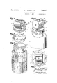
lin Athe drawings, Figures 1, 2 and 3 are perspective views :of the three 'elements of 4a measuring container constructed in accordance `with this invention;
Fig. '4 "is a perspective view of the assembled container, the lowerjpart of the jar being broken V away? (c1. ce1- 107) Fig. 5 isv a plan View of the container shown in Figs. 1 and 4.;
Fig. 6 is a .sectional view on the line '6-6, Fig. 5; v
. Fig. 7 'is a View similar to Fig. 6 but illustrating the manner in which the dispensing operation is performed;
`Fig. 8 is a side elevation, partly in section, .of a different form of container adapted for the attachment thereto of the measuring device shown in Fig. l, said device 'being shown in dotted lines;
Fig. 9 is a lsectional view ofa cover rfor the containershown in Fig. Svand Fig. 10 is a sectional view` of the upper part of another form of container `adapted for use With the measuring device shown in Fig. 1.
Referring first to Figs. 1 to 7, inclusive, the apparatus there shown comprises a container `2, which Vmay conveniently take the form 'of a glass jar, a volumetric measuring device indicated in general at 3, and a sheet metal locking ring 4 for securing the parts 2 and 3 non-releasably to each other. For this purpose thevjar 2 is provided With 'a circumferential enlargement -o-r collar portion 45 -againstwhich thelower -end of 4the ring 4 abuts and the measuring device has a corresponding circumferential member -6 against which the upper end of the ring bears. Between the portions 5 and 6 the surface of the jar 2 and of. the base of the rneasuringlwdevice 3 are of -gen- 'eral'ly cylindricalv form` and Lof `substantially the same-diameter, but thecylindrical surface rof the jar is interrupted 'by a circumferential groove 7, while the corresponding surface of the measuring device is interrupted by 'a similar groove 8. Theshoulders of these grooves adjacent to each other are made square or at right angles with reference to the cylindrical Ysurfaces of the parts or else are slightly undercut, and the locking ring 4 is provided -with upper-andlower series of `inwardly bent integral spring fingers I9 and 10, respectively, which snap` into the two grooves 8 and7,'resp ec'tively`. with the free ends-of the lugs in engagement with the yshoulders just mentioned. Itvvill be clear from aninspection of Figs. 4 and 6 that when the parts are in this relationship the measuring device 3 Will be secured vviirmly to the jar or container 2.` Furthermore, due to the `nature of the construction it is `practically impossible for a person to 'remove the measuring device from the container without either destroying one of the elements 2, v3 4or 4, or "at least so mutilating it that it lcannot 'be lused yfor -further for its intended function.
1 l The measuring device must, however, be lreleased from the jar in forder -to permit 4the `re iill'ing of the jar when 'the supply of coffee in it has become exhausted. For lthis purpose the ring 4 is `made with a breakable portion so :that
LGO
izo
irlo
it can be taken off easily but will be destroyed in so doing. As shown in Fig. 2 the yring is made from a long narrow strip of sheet metal and the two end portions-are overlapped one upon the other and secured together by a soldered union 12, the extreme tip 14 of one end being left free and preferably being tapered to receive a winding key of the type commonly used in winding up the tear strip or rip strip of a tin can so that this end portion can easily be wound in the same manner and by a similar key sufficiently to break the soldered joint 12. This destroys the ring and permits the separation of the parts 2 and 3 from each other,
, In using this apparatus it is contemplated that when the housewife purchases a fresh supply of coffee she will transfer it immediately from the bag, can, or other container in which it has been sold to the jar 2. With this purchase a ring 4 will be given her. After filling the jar with the coffee she places the ring over the top of the jar and forces it down until it strikes the shoulder 5, this movement resulting in snapping the lugs into the groove?. She then inserts the lower reduced end of the base of the measuring device in the top of the ring and presses it down until it brings up on the shoulder 6. Before this oecurs, however, the` rings 9 will have snapped into the groove 8, thus locking the measuring device and the jar securely together. Preferably a rubber gasket is introduced between the meeting ends of the parts 2 and 3 to reduce air leakage through this joint.
The measuring device, in the specific form Shown, comprises a cylinder 16, closed at its opposite ends, and mounted to revolve in a cylindrical casing 17. -The casing is made integral with or is rigidly secured to a base 18. Within the cylinder is a measuring chamber which may extend entirely across the cylinder from one end thereof to the other, but which is provided with straight parallel side walls and with a movable bottom 21 fitting snugly between said walls'. The end of the chamber opposite to its bottom is normally open and the cylinder may be rotated about its own axis to bringv said open end into register with an inlet port 22 Fig. 6,. through which the coffee can ow freely from the container into the measuring chamber when the con.- tainer is in its inverted position. After the' cham.- ber has been filledr in this manner the cylinder can then be revolved into a diametrically opposite position in which its open end will be brought into register with the discharge port 23 in the casing, as shown in Fig. 7. If -the container is still maintained in its inverted position the coffee will drop. freely out of the measuring ,chamber by gravity. Consequently, uniformly measured quantities of coffee can be dispensed from the container at each operation of the measuring device. In addition, thecylinder fits tightly within the casing and the joint between the measuring device and the container is made relatively tight so ythat while the apparatus is not air tight in the strict scientific sense of that term, nevertheless it is sufficiently tight to prevent any substantial interchange of gaseous constituents between the interior of the apparatus and the outside atmossphere. Consequently, the aroma and freshness of the coffee will be preserved for a very considerable length of time, usually for such a period thatthe entire supply will have been used before any substantial deterioration has occurred. f
In order to enable the user to adjust the volume of the measuring chamber 20 to her individual requirements, a screw 25 is threaded through the bottom piece 21 and the'head of this screw is held between the wall of the cylinder 16 and a buckled plate 26 which nts tightly between the walls of the chamber below the bottom 2l. A hole 27 through the cylinder 16 and in line with the screw head permits the introduction of a screw driver blade to rotate the screw. When so rotated it moves the bottom 21 upward or downward, depending upon the direction of such rotation. In assembling these parts the buckled plate 26, with the screw 25 projecting through it, is inserted in the measuring chamber and is slid downwardly until the margins of the plate bring up on the inner wall of the cylinder. The plate tends to straighten and its corners therefore dig into the walls of the chamber and effectually resist any tendency to move the plate upwardly. A washer 28 may or may not be used between the head of the screw and the plate 26.
, For convenience in assembling the cylinder 16 in its casing, the casing is made with one open end, as indicated in Fig. 5, so that the cylinder may simply be slipped into it and then secured against removal by means of a screw 29 with its inner end riveted over. The outer end of the cylinder is provided with a thumb piece 30 for convenience in revolving the cylinder. A pin 31, Fig. 1, cooperates with shoulders on the exposed end of the cylinder to limit the rotative movement of the cylinder to approximately a half turn.
The construction above described provides a dispensing container in which a supply of coffee can be kept indefinitely and from which measured quantities can be discharged as needed. At the same time the construction of the apparatus is such that deterioration of the coffee will be reduced to an extremely low and tolerable rate. 1n addition, it provides anapparatus suited to the requirements of individual proprietors since they canfurnish their customers with a dispensing apparatus which will require the use of a locking ring 4 of va certain definite size. By adopting a size different from that of a competitor a proprietor can make it extremely difficult, if not impossible, for a customer to use this device with a competitors coffee.
ids
For those proprietors who put up their coffee the can. Such a can may be provided with a tear strip, or the edge of the base 18 may be grooved vertically, as shown at 34 in Fig. 5, to permit the introduction of a sharp pointed instrument behind the upper edge of the can where it can be forced downwardly and tear the top of the can open. The margin of the lcan can then be forced outwardly a little at a time until the entire base of the measuring device is freed from it. The top of the can 32 is designed to be closed by a cover 35,-Fig. 9. l
, Fig. 10 shows the general type of can used by those proprietors who seal their coffee in inert gas, vacuum, or the like. These cans have a circumferential tear strip or rip strip, the end of which is shown in Fig. 10 at 36, this strip being formed in the outer wall of the can. Such a' can usually, or at least frequently, has an inner rim 37 over which the top can t frictionally when the can has been opened by tearing out the strip 36. For the purposes of this invention the rim 37 is provided with integral inwardly bent spring fingers or lugs 38, like the lugs 33, and adapted to enter the groove 8 of the base 18 of the measuring device and lock this base to the top of the can after the cover has been removed, in exactly the manner that the lugs 33 lock the measuring device to the can 32 in the construction above described.
This apparatus thus is useful both with coffee sold in bulk and also with that sealed in tin cans or similar containers. `In addition, the apparatus is useful even without the ring 4, the base of the measuring device being secured to the jar by the ordinary screw connection, by a bayonet joint, or by any other releasable connection, such as those commonly used for securing a cover to a Jar.
While we have herein shown and described preferred embodiments of our invention, it will be understood that the invention may be embodied in other forms without departing from the spirit or scope thereof.
Having thus described our invention, what we desire to claim as new is:
1. An apparatus of the character described, comprising a container, a volumetric measuring device, and means for securing said device to said container against removal therefrom, comprising ing a ring carried by said container and provided with a plurality of spring lugs, and said device having a connecting part to be engaged by said lugs whereby such engagement will non-releasably secure said device to said container.
2. An apparatus of the character described, comprising a container, a volumetric measuring device, and means for securing said device to said container against removal therefrom, comprising a ring carried by said container and provided with a plurality of spring lugs, and said device having a connecting part to be engaged by said lugs whereby such engagement will non-releasably` secure said device to said container, said ring including a portion readily breakable to permit the release of said device when desired.
3. An apparatus of the character described, comprising a dispensing device including a casing, a cylinder mounted therein for rotative movement about the axis of the cylinder, said cylinder having an open ended measuring chamber, and said casing having inlet and discharge openingswith which said chamber may be brought into register at different points in its rotative movement to fill and discharge the chamber, said measuring chamber including a straight sided portion of substantially uniform internal diameter, a bottom mounted in said straight sided portion, a screw threaded through said bottom and having its head located within said cylinder, and a buckled retaining plate for said head located between the head of said screw and said bottom and jammed against the walls of the chamber to hold it in its buckled position.
4. An apparatus of the character described, comprising a container, a volumetric measuring device, and. means for securing said device to said container against removal therefrom, comprising a ring carried by said container and having parts for operatively engaging parts of said device to positively prevent the release of said device from said container' without substantially destroying the ring.
5. An apparatus of the character described, comprising a container, a volumetric measuring device, and means for securing said device to said container against removal therefrom, comprising a ring having parts adapted to be operatively engaged with parts of one of said elements by aA movement in a given direction, but thereafter positively preventing the separationof said ele- 1 ments, whereby an essential part of the apparatus must be substantially destroyed in order to remove said device from said container. f
6. An apparatus of the character described, comprising a container, a volumetric measuring device, and means for securing said device to said container against removal therefrom, comprising a ring carried by said container' and having parts for operatively engaging parts of lsaid device to positively prevent the release of said device from said container, said ring having a breakable portion to permit the rupture of the ring when it is desired to remove said device from said container.
7. An apparatus of the character described, comprising a dispensing device including a casing, a cylinder mounted therein for rotative movement about the axis of the cylinder, said cylinder having an open ended measuring chamber, and said casing having inlet and discharge openings with which said chamber may be brought into register at different points in its rotative movement to flll and discharge the chamber, a container, and a unitary metallic locking means for securing said device to said container in such a manner that they cannot be separated without destroying said locking means.
8. An apparatus of the character described comprising a container, a volumetric measuring device, and a unitary non-releasable metallic locking device for so securing together said container and said measuring device that the separation of said measuring device from said container is rendered impossible without destroying said locking device. 120
9. An apparatus of the character described, comprising a container adapted to hold a quantity of coffee or other granular material, a volumetric measuring device operable to discharge said material from the container in definite measured quantities but, so joined to said container as to normally maintain said container closed against any substntial interchange of air with the outside atmosphere, and a unitary non-releasable metallic locking device for so securing said measuring device to said container that the separation of the measuring device from the container is rendered impossible without destroying said locking device.
10. A locking ring formed of a strip having a series of inwardly bent spring lugs struck up from the body of the ring below the upper `edge thereof and a series of inwardly bent spring lugs struck up from the body of the ring above the lower edge thereof, the free ends of the two series of lugs projecting in opposite directions, one end of said strip overlapping the other, and means forming a separable joint between the overlapped portions, said lend projecting freely from said joint.
' 145 CHARLES R. LOTHROP.
OSWALD CAMMANN.
Priority Applications (1)
| Application Number | Priority Date | Filing Date | Title |
|---|---|---|---|
| US641460A US1982917A (en) | 1932-11-05 | 1932-11-05 | Dispensing apparatus |
Applications Claiming Priority (1)
| Application Number | Priority Date | Filing Date | Title |
|---|---|---|---|
| US641460A US1982917A (en) | 1932-11-05 | 1932-11-05 | Dispensing apparatus |
Publications (1)
| Publication Number | Publication Date |
|---|---|
| US1982917A true US1982917A (en) | 1934-12-04 |
Family
ID=24572486
Family Applications (1)
| Application Number | Title | Priority Date | Filing Date |
|---|---|---|---|
| US641460A Expired - Lifetime US1982917A (en) | 1932-11-05 | 1932-11-05 | Dispensing apparatus |
Country Status (1)
| Country | Link |
|---|---|
| US (1) | US1982917A (en) |
Cited By (12)
| Publication number | Priority date | Publication date | Assignee | Title |
|---|---|---|---|---|
| US2742195A (en) * | 1952-02-11 | 1956-04-17 | Merck & Co Inc | Dropper closure for containers |
| US2779512A (en) * | 1954-07-08 | 1957-01-29 | Steele | Powder dispenser |
| US3893599A (en) * | 1972-10-25 | 1975-07-08 | Cornelius Co | Means for dispensing |
| US4162751A (en) * | 1977-01-03 | 1979-07-31 | Lillian Hetland | Rotary measuring chamber with size adjustment |
| US5651231A (en) * | 1994-08-26 | 1997-07-29 | Garland; Thomas A. | Valving |
| US5765339A (en) * | 1994-08-26 | 1998-06-16 | Garland; Thomas A. | Diaper pail |
| US20080044267A1 (en) * | 2006-06-23 | 2008-02-21 | Gunther Holzwarth | Portion feed device for packaging |
| US20080296297A1 (en) * | 2005-08-04 | 2008-12-04 | Olympus Corporation | Lid structure of reagent container |
| US20130168418A1 (en) * | 2010-09-06 | 2013-07-04 | Eugene Druyan | Container for Dispensing Liquid Doses |
| US20190326006A1 (en) * | 2018-04-24 | 2019-10-24 | Arrix, Inc. | Systems and methods for medication management |
| WO2020146917A1 (en) * | 2019-01-17 | 2020-07-23 | Silvio Morello | A measured powder dispenser |
| US11335448B2 (en) | 2018-04-24 | 2022-05-17 | Arrix, Inc. | Systems and methods for medication management |
-
1932
- 1932-11-05 US US641460A patent/US1982917A/en not_active Expired - Lifetime
Cited By (17)
| Publication number | Priority date | Publication date | Assignee | Title |
|---|---|---|---|---|
| US2742195A (en) * | 1952-02-11 | 1956-04-17 | Merck & Co Inc | Dropper closure for containers |
| US2779512A (en) * | 1954-07-08 | 1957-01-29 | Steele | Powder dispenser |
| US3893599A (en) * | 1972-10-25 | 1975-07-08 | Cornelius Co | Means for dispensing |
| US4162751A (en) * | 1977-01-03 | 1979-07-31 | Lillian Hetland | Rotary measuring chamber with size adjustment |
| US5651231A (en) * | 1994-08-26 | 1997-07-29 | Garland; Thomas A. | Valving |
| US5765339A (en) * | 1994-08-26 | 1998-06-16 | Garland; Thomas A. | Diaper pail |
| US7648037B2 (en) * | 2005-08-04 | 2010-01-19 | Olympus Corporation | Lid structure of reagent container |
| US20080296297A1 (en) * | 2005-08-04 | 2008-12-04 | Olympus Corporation | Lid structure of reagent container |
| US20080044267A1 (en) * | 2006-06-23 | 2008-02-21 | Gunther Holzwarth | Portion feed device for packaging |
| US20130168418A1 (en) * | 2010-09-06 | 2013-07-04 | Eugene Druyan | Container for Dispensing Liquid Doses |
| US9016529B2 (en) * | 2010-09-06 | 2015-04-28 | Eugene Druyan | Container for dispensing liquid doses |
| US20190326006A1 (en) * | 2018-04-24 | 2019-10-24 | Arrix, Inc. | Systems and methods for medication management |
| US10896750B2 (en) * | 2018-04-24 | 2021-01-19 | Arrix, Inc. | Systems and methods for medication management |
| US11335448B2 (en) | 2018-04-24 | 2022-05-17 | Arrix, Inc. | Systems and methods for medication management |
| WO2020146917A1 (en) * | 2019-01-17 | 2020-07-23 | Silvio Morello | A measured powder dispenser |
| CN113453587A (en) * | 2019-01-17 | 2021-09-28 | 西尔维奥·莫雷洛 | Metered powder dispenser |
| US11452394B2 (en) | 2019-01-17 | 2022-09-27 | Silvio MORELLO | Measured powder dispenser |
Similar Documents
| Publication | Publication Date | Title |
|---|---|---|
| US1982917A (en) | Dispensing apparatus | |
| US4074827A (en) | Multi-purpose closure for containers | |
| US2840124A (en) | Reuseable dispensing cover | |
| US3861284A (en) | Cup lids for use with teabags and the like | |
| US9114920B1 (en) | Beverage container lid with integral snack and beverage enhancing features | |
| NZ210579A (en) | Spouted container and cover therefor | |
| US3077213A (en) | Self-contained measuring and dispensing spout | |
| US2104332A (en) | Rotatable dispensing and measuring device | |
| US2034067A (en) | Container for ice cream, etc. | |
| US1914766A (en) | Bottle cap | |
| US3694235A (en) | Disposable food-vending package | |
| US3162882A (en) | Merchandising package | |
| US3262600A (en) | Tamper-proof replaceable cap | |
| US2750081A (en) | Cover member for dispensing valve structure | |
| US2321869A (en) | Dispenser for dry materials | |
| US10029821B2 (en) | Retainable scoop and container | |
| US1590636A (en) | Collapsible container | |
| US1775959A (en) | Dispensing receptacle | |
| US2332768A (en) | Package for granular material | |
| US1875379A (en) | Container | |
| WO2017034544A1 (en) | Beverage container lid with integral snack and beverage enhancing features | |
| US2262812A (en) | Canned liquid dispenser | |
| US4109830A (en) | Tiltable trap chamber with stack aiding feature | |
| US3226000A (en) | Cup with destruction inducing means | |
| US1741991A (en) | Paste ejector |