US1981908A - Boat - Google Patents
Boat Download PDFInfo
- Publication number
- US1981908A US1981908A US563909A US56390931A US1981908A US 1981908 A US1981908 A US 1981908A US 563909 A US563909 A US 563909A US 56390931 A US56390931 A US 56390931A US 1981908 A US1981908 A US 1981908A
- Authority
- US
- United States
- Prior art keywords
- boat
- disc
- vessel
- lug
- rudder
- Prior art date
- Legal status (The legal status is an assumption and is not a legal conclusion. Google has not performed a legal analysis and makes no representation as to the accuracy of the status listed.)
- Expired - Lifetime
Links
- 230000001276 controlling effect Effects 0.000 description 19
- 230000006978 adaptation Effects 0.000 description 3
- 238000010276 construction Methods 0.000 description 3
- 238000000034 method Methods 0.000 description 3
- 230000001419 dependent effect Effects 0.000 description 2
- 230000000694 effects Effects 0.000 description 2
- 239000002184 metal Substances 0.000 description 2
- 230000000452 restraining effect Effects 0.000 description 2
- XLYOFNOQVPJJNP-UHFFFAOYSA-N water Substances O XLYOFNOQVPJJNP-UHFFFAOYSA-N 0.000 description 2
- 229910000831 Steel Inorganic materials 0.000 description 1
- 238000005452 bending Methods 0.000 description 1
- 238000007664 blowing Methods 0.000 description 1
- 238000006073 displacement reaction Methods 0.000 description 1
- 238000012986 modification Methods 0.000 description 1
- 230000004048 modification Effects 0.000 description 1
- 230000001105 regulatory effect Effects 0.000 description 1
- 238000004904 shortening Methods 0.000 description 1
- 239000010959 steel Substances 0.000 description 1
Images


Classifications
-
- A—HUMAN NECESSITIES
- A63—SPORTS; GAMES; AMUSEMENTS
- A63H—TOYS, e.g. TOPS, DOLLS, HOOPS OR BUILDING BLOCKS
- A63H23/00—Toy boats; Floating toys; Other aquatic toy devices
- A63H23/02—Boats; Sailing boats
- A63H23/04—Self-propelled boats, ships or submarines
-
- B—PERFORMING OPERATIONS; TRANSPORTING
- B63—SHIPS OR OTHER WATERBORNE VESSELS; RELATED EQUIPMENT
- B63H—MARINE PROPULSION OR STEERING
- B63H25/00—Steering; Slowing-down otherwise than by use of propulsive elements; Dynamic anchoring, i.e. positioning vessels by means of main or auxiliary propulsive elements
- B63H25/02—Initiating means for steering, for slowing down, otherwise than by use of propulsive elements, or for dynamic anchoring
- B63H25/04—Initiating means for steering, for slowing down, otherwise than by use of propulsive elements, or for dynamic anchoring automatic, e.g. reacting to compass
Definitions
- V16 Claims. (Cl. 46-37) This invention relates to boats, and more particularly to boats provided with control means for causing them to move in a predetermined The present invention relatesparticularly to means for controlling the movement of toy sail boats, andthe like, but it is to beunderstood that it is applicable to toy motor boats and other devices as will hereinafter appear.
- the present invention may be used for that purpose.
- atoy boat with a control for causing the boat tov move in a predetermined direction or seriesof directions
- Thev particularembodimentsfof the inventionv selected for illustration cause the boat to travel out over the water straight ahead orisubstantially y straight ahead for a predetermined period of time ora predeterminedA distance and then to turn around and return to the original starting point.
- I preferably employ means for turning the 4tiller bar to an angular position after a definite predetermined travel, and for maintaining the tillerbar in such an angular position until the boat comes about or reverses ⁇ its direction, whereupon the main boom of the boat swings from the newly presented Windward side to the leeward side of the vessel and causes the tiller to assume a position enabling the vessel to travel in the reverse direction to its original starting position or to position in proximity to the originall starting position.
- I also provide means for allowing a vessel to be put out running free and to come about and I'return close hauled.
- the sheets are allowed to be fully extended, which permits the sails and the associated booms-toassume a free running position.
- the comingabout mechanism As the comingabout mechanism is released, the boat swings about or reverses its direction, and as it begins to straighten out on its return, the coming-about mechanism causes the sheets to be drawn up, resulting in the sails assuming a fclose hauled position for the return movement.
- the sheets are actuated after the tiller has been moved to an angular position,and ⁇ the vessel sets out on a different tack with the main sail automatically vswung into the proper position.
- This setting can be varied to produce any desired Aor predetermined movement ofV the vessel.
- the device is equally applicable. tov ayawl, in which'there are three sails to be hauled in, and can be modified to'haul in as many sails 'as the 95 vessel carries.
- the mechanism is adaptable to any type of sailing vessel and can haul in one or a plurality .of sails.
- a small wind vane preferably formed of metal, and mounted as a flag or the like on the boat, is adapted tohold the rudder in angular position while the boatis turning about, and then releases the mechanism to return the rudder to its normal position.
- the controlling means of the present invention comprises a spring actuated disc, an escapement or latch releasing mechanism controlled so as to be released at any predetermined time, means for engaging the tiller bar of the vessel to actuate the rudder for turning the boat, and a stop for maintaining the tiller bar in its angular position only until the vessel has come about.
- Figure 1 is a fragmentary side elevation or a sailing boat provided with my novel control means
- Figure 2 is a fragmentary plan View of the, deck portion of the boat shown in Figure l, illustrating in detail thel arrangement of my ⁇ controlling means;
- Figure 3 is a plan view similar to Figure 2 showing the device in operating position
- Figure 4 is a fragmentary elevational view of a vessel similar to the vessel shown in Figure 1, but provided with the modiiied form of my device which is adapted to be used when the vessel is sailing close hauled;
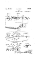
- FIG. 5 is a fragmentary plan view of the deck construction and the mounting of my controlling means thereon;
- Figure 6 is a fragmentary elevational View of a motor boat provided With myV novel controlling means
- Figure '7 is a fragmentary plan view of the motor boat shown in Figure 6;
- Figure 8 is a fragmentary plan View of an embodiment forv putting out running free and returning close hauled.
- Figure 9 is an elevational View of the spool shown in Figure 8, with the sheets in section.
- the boat is indicated generally bythe reference numerallo. It has the hull portion 11, the keel 12, and is provided with a main sail indicated by the numeral 13. The bottom edge of the sail 13 is attached to the main boom 14, which is pivotally connected to a suitable mast, not shown. ⁇
- the sail 13 is secured to the boom 14 by means of the lacing 15, as is well known and does not need to be described, in detail.
- a vertically mounted pivotal post member 16 Projecting through the rearwardly extending portion of the hull 11 is a vertically mounted pivotal post member 16 provided at its lower end with the projecting flat rudder portion 17.
- a pin 18 prevents the upward movement of the post 16.
- a cap member 19 is secured to the upper portion of the post ⁇ 1,6,which projects upwardly past the deck lineof'thefvessel and is provided with a diametrical opening adapted to receive the tiller bar 20.
- This tiller bar 20 is secured in the opening in the' cap 19 and serves to impart rotating movement to the rudder 17.
- the outer end of the tiller bar 20 is provided with a loop or eye portion 21 which receives vone end of a spring 22.
- the other endof the spring 22 is secured in a suitable eye member 23screwed or otherwise fastened into the deck end of the hull 11.
- the spring 22 is provided for ⁇ normally maintaining the rudder in a straight line vor/substantially straight line position.
- the disc 24 is provided with a suitable projecting lug member 27 adapted to be normally engaged by a lug or pawl member 28 provided on the release lever 29. This release lever is pivoted on the deck and in the plane of the disc 24 by means of a pin 30.
- the extending end of the lever 29 is provided with an enlarged portion adapted to receive a pull chain or cable member 31 which is connected to the rotating portion 32 of a time-piece or control mechanism 33.
- This control mechanism may comprise a watch or any suitable actuated means.
- it is an ordinary time-piece provided with the usual spiral, spring (not shown), this springbeing Wound by a prg.. jecting stem 34, and connected to turn shaft 32.
- stop-watch might be used for this purpose and adapted to be so set that upon a given amount of rotation or given number of rotations of the rotating mechanism 32,v the cable member 31 will pull the latching memberv 29 from engagement with the lug ⁇ 27 of the disc 24 and allow the,
- the rotating member or shaft 3,2 has aY pointer 32a. cooperating with a scale B2b which may be, graduated to indicate the time or distance of means, in the manner now employedY in setting4 a stem windingr watch.
- a scale B2b which may be, graduated to indicate the time or distance of means, in the manner now employedY in setting4 a stem windingr watch.
- the disc 24 is provided with an upwardly projecting lug memben 35V carried preferably near the outer periphery thereof.
- a second lug member 36 depends from the lower surface of the disc 2,4 and is positioned in radial alignment with the lug 35, but is spaced a short distance inwardly therefrom.
- the lug 35 may comprise a peg member adapted to seat in a corresponding opening in the disc 24. 1f desired, several openings might be provided at different distances from the center of the disc, such as the hole indicated at 35a, which would actuate thetiller to effect tacking instead of coming-about completely.
- partial rudder actionv only is effected, the action being controlled by the position which the lug 35 oc-y cupies with respect to the centerof the disc.
- This stop mechanism comprises a stop lever 38 preferably formed of a steel rod of suflicient diameter to resist bending,this rod passing through two bearings supports 39, 39 fastenedto the deck of the hull.
- the rod 38 has the upwardly extending end portion which is flattened to provide a stop means which engages the depending lug 36 secured to the disc r24.
- This upturned and attenedfend 40 is adapted to hold the disc 24 from further rotation and results in the tiller bar 20 being held in the angular position shown in Figure 3 while the boat is swinging about.
- the boom 14, actuated by the'sail 13 swings from the Windward side ⁇ of the vessel to the leeward side thereofthe boom k14 contacting the upwardlyv extending end 41A of the rod 38. This causes the rod 38 to be turned or ro'- tated in the bearings 39 and releases the lug 36 from the stop 40. ⁇
- the spring 26 then urges the disc to rotate f further in a counter-clockwise direction
- the tiller bar 20 returns to itsnormal position, and is held by the tension in the spring member 22 connected therewith.
- a stop member 42 is provided o-n the deck of the hull 1l and projects upwardly to Contact with the depending lug'36 of the disc 24 to limit further rotational movement of the disc after the. tiller bar has once been actuated and disengaged.
- the boom 14 carrying the main sail 13 swings from the Windward side thereof ⁇ to theleeward side, causing the upturned end 41 of the control rod 38 to be knocked over, resulting in release-of the lug 36 and thefurther rotation ⁇ ofl the disc 24 to itsfinoperative position, where it is.v stopped by means of the lug 42.
- the tiller bar returns to its normal position due to the tension in the spring member 22, and the result is that the boat is reversed and returns to its original starting position in a straight line or substantially straight or at least along its path of travel outwardly from its starting point.
- the control mechanism33 may be regulated so that it will operate at any desired time, and the position of the stop 40 may be such that thetiller'bar can beheld at an angle either greater or less than that shown in Figure 3, depending upon the space in which the vessel 10 has to come about and return to its original position.
- a knot is-formed in the end of the sheet and forms a loop adapted to fit over a control or latching bar 49 which is carried in suitable bearings fastened to the deck of the hull 11.
- the latching bar 49 is preferably of U-shaped structure and fits intotsuitable openings formed in a v yoke or supporting member -50 fastened by means of -the stud member 5l into the hull l1.
- the outwardly projecting end of the latching rod 49 isl adapted to have abutting contact with the depending lug 36 secured to the disc 24. As the disc 24 rotates, the lug 36 thereof is adapted to engage the stop provided by the control rod 38', and is held in this position While the vessel swings about.
- a secondary sheet 52 is secured outwardly from the sheet 45 upon the boom 14'l and passes through a second eyelet 53 positioned on the tiller bar ⁇ 20'.
- This second sheet 52 is of much greater length than the sheet 45 and is adapted to allow the boom 14 to swing to its free running position.
- the end of the sheet 52 is fastened to a stanchion or pin member 54 secured in the deck of the hull 11. y y f It is to be understood that the eyes 46 and 53 are adjustable along the tiller bar 20, and the distancethat the eyes are positioned from the pivot point 19 is dependent upon the leverage de- However, when the boat is traveling beforethe windymorevpressure on'the rudder is required,
- 6l is provided with means for receiving a spring erence numeral 55. It is provided with a propeller 56 adapted to be energized by any suitable motor means, such as a rubber band or a This detail forms no part of the present invention.
- a rudder member is adapted to be placed in a cut out portion of the hull and has the rudder post 59 attached thereto extending upwardly 3 through the hull 55 and surmounted at its upper end by a cap member 60.
- the cap member is provided with a suitable opening for receiving the tiller bar 6l, this tiller bar corresponding to the tiller bar 20 of the embodiment shown in
- the outer end of the tiller bar member 62 which normally urges the tiller bar into the straight line position, best shown in Figure 7, the rudder member 58 is aligned with the longitudinal axis of the hull 55.
- the other end of the spring 62 is secured in a suitable support fastened in the hull 55 of the boat and indicated by the numeral 64.
- the mechanism for rotating the tiller bar 61 about the rudder post 59 is the same as that shown in Figures l to 5, Vand comprises the disc 24 with the upwardly projecting lug 35 and the downwardly projecting lug 36".
- the escapement or release lever 29" ( Figure 7) lis shown as in its operative position, holding the disc 24 against rotation.
- 'Ihe spring meniber 26" is adapted to rotate the disc 24 upon release of the lever 29 and forces the lug 35 into contact with the tiller bar 61 holding the tiller bar in an angular position.
- the depending lug 36 of the disc 24" is adapted 4to contact with thev end 65 of a control rod 66, and holds the tiller bar 6l in angular position with respect to the hull 55.
- the control 66 which is adapted to be mounted in suitable bearings 67 secured to the deck of the hull 55, extends forwardly and at its ends is provided with enlarged circular portion 68 adapted to t around an eccentric 69 secured to a flag stair 70.
- a small metal flag or vane is mounted on the staif 70 and serves as a means for releasing the lug 36" from the end of the rod 65 and permitting the tiller bar to assume its normal position.
- the flag 71 is initially set in a position corresponding to the direction'in which the Wind is blowing as the vessel is put out.
- the r'e. lease mechanism 29 operates and the disc 24" rotates, causing the boat to start to come about, the ilag 7l isaiected by the wind and rotates the eccentric 69.
- the flag '71 assumes a position 189 degrees irom the position shown in Figure l7, and causes the eccentric 69 to pull the control rod 66 forwardly, releasing the vlug 36 from the end 65 thereof and allowing the disc 24 to rotate back to its position against the stop lug 42.
- the spring 62 then, turns the tiller bar 6l to normal position, causing the rudder 58 to straighten the ship out and return it to its original starting position.
- the coming-about mechanism is provided as in the embodiment of Figures 4 and 5. It comprises the disc 86 having the upwardly projectingl lug 81 corresponding to the lug 35 of Figure 4, and is provided with a suitable spring, not shown, for rotating the disc in a counter-clockwise direction.
- the disc is provided with the usual depending lug, not shown, corresponding to the lug 36 of Figure 4, this lug being adapted to be engaged by the usual stop mechanism 82, similar to the control rod 33 of Figurer l. 'Ihe operation of the device up to this point is as described in connection with Figures l to 3 and needs no further detailed description.
- the flattened upturned end portion 83 of the stop mechanism holds the tiller bar 84 in angular position for changing the tack of the boat and allowing it to come about.
- This latching bar is mounted for longitudinal movement in a suitable guide or support 86 secured to the deck of the vessel, and is provided with a collar 87 for limiting the movement of the rod in the guide.
- the latching rod 85 has sliding engagement in a suitable yoke or supporting member 88 corresponding to the member 50 of Figure 4.
- This yoke'rnember is provided for permitting the vessel to maneuver as described in connection with Figures 4 and 5, which maneuver isexactly the opposite of the maneuver possible in connection ⁇ with Figures 8 and 9.
- the lower portion of the latching rod 85 has av projecting portion 89 which is adapted to form a release f or the sheet controlling mechanism indicated at 90.
- This sheet controlling mechanism comprises a reel 91 provided with an outwardly projecting pawl 92 adapted to be engaged by a suitable dog 93 pivoted on a pivot shaft 94 secured to the deck of the vessel.
- the reel 91 comprises one of a pair of discs adapted to form the outer surfaces of a pulley indicated at 95.
- the jib sail or other sheet 96 and the main sail sheet 97 arevadapted to be secured about the pulley portion of the sheet controlling mechanism 90.
- the controlling mechanism is adapted to be supported by means of a shaft 98 suitably mounted in the deck of the vessel and is provided with a spring 99 adapted to rotate the reel 91 and the associated pulley 95 in' a counter-clockwise direction.
- the projecting end portion 89 of the latching rod 85 may be formed soas to provide a stop for limiting the amount of rotation of the reel 91, so that the disc will rotate only to a position where the pawl 92 is engaged bythe projecting portion 89 of the rod. This will resultin the rod causing the boom and main vsail to assume a position which is not a close hauled position and which will result in the 'boat changing tack from not coming completely about and returning to its starting position.
- a vessel may s et out on a given tack and at a preselected period of time change tackand vary its course without returning to,v itsoriginal p'osition.
- v ⁇ f 1 It is also contemplated that the spring 99 may be rotated justsufliciently so that the tension within the spring'will cause the disc 91 to rotate only to the amount desired for changing the tack of a vessel without completely reversing its movement. This adjustment may be made such that the disc 91 will make 1, 2, or a plurality of revolutions, depending upon the tension which has been put into the spring member 99 and will thus vary the angular direction that the vessel assumes in setting out on its new tack.
- My novel movement controlling mechanism for boats is thus applicable to either sailing vessels or motor boats, and can be used on either to control the movement thereof. Also, the device is operative upon boats which may be sailing against the wind in one direction and with the wind in the opposite direction. I do not intend to be limited to the exact details shownI and described, but only in so far as deiined by the spirit and scope of the appended claims.
- steering means mechanically to reverse the direction of travel of the boat after a preselected timecontrolled movement, andmeans for positively returning'the steering-.means to initial position upon reversal of the'boat.
- a boatymovement-'controlling mechanism comprising a disc, means for'rotating said disc, latching means restraining said disc, means for releasing said latching means When said boat has n releasing said stop means when saidboat has turned about to return said tiller to its initial unrotated' position.
- a lrotatable disc In a sailing boat, a lrotatable disc, latching means therefor, adjustable latch releasing mechanism, steeringv means for said boat, means carried by said discffor engaging said steering means when saidy disc is rotated, stopf means for maintaining said steering Vmeans inactuated position, and means actuated by *the change of tack ⁇ of saidv boat for releasing saidflast named means when said boat has turnedabout. ⁇ g
- a rudder In a boat, a rudder, steering means secured to said rudder, rotating means adapted to engage said steering means at a predetermined time for automatically forcing said steering means to an angular position with respect to said boat, stop means for maintaining said steering means in said angular position, and means adapted to release said stop means to return said rudder automatically to normal position.
- movement controlling mechanism comprising a disc, spring means for rotating said disc, latching means restraining said disc,Y
- adjustable means for releasing said latching means when said boat has beeny moving a predetermined period of time, a rudder for guiding said boat, a tiller bar secured to said rudder, a projecting lug on said disc adapted to force said tiller bar automatically .into an angular position with respect to said boat upon rotation of said disc, stop means for holding said disc in position for maintaining said tiller bar in said angular position, and means for releasing said stop means to return said tiller bar automatically to normal position.
- time controlled means adapted to engage said steering means after a predetermined time to displace said steering means angularly
- adjustable pin means carried by said time controlled means for determining the angular displacement of said steering means, and means actuated by change of tack of said boat for releasing said steering means to initial position.
Landscapes
- Engineering & Computer Science (AREA)
- Ocean & Marine Engineering (AREA)
- Chemical & Material Sciences (AREA)
- Combustion & Propulsion (AREA)
- Mechanical Engineering (AREA)
- Soil Working Implements (AREA)
Description
ml """www "u 36 H. G. DUGAN Bom Filed Sept. 2'1, 1931l Nov. '27, 1934.
5 sheets-sheet 1 V f r M9 i H. G. DUGAN Nov. 27, 1934.
BOAT
Filed Sept. 21, 1951 3 Sheets-Sheet 2 Nov. 27,` 1934. H. G. DUGAN BOAT Filed sept. 21,'1951 .'5 Sheets-Sheet 3 m Y@ ew', w IIIIIIHI @of 5 W3@ om l (f, w 3 YM 7 6 Patented Nov. 27, 1934 PATENT OFFICE y BOATA I i Hugh G. Dugan, Hinsdale, Ill. Application September 21, 1931, Serial No. 563,909
V16 Claims. (Cl. 46-37) This invention relates to boats, and more particularly to boats provided with control means for causing them to move in a predetermined The present invention relatesparticularly to means for controlling the movement of toy sail boats, andthe like, but it is to beunderstood that it is applicable to toy motor boats and other devices as will hereinafter appear.
It is' to be understood also that if, for any reason, it is desired to have a pilotless full-sized `or substantially full-sized boat go out over the water and return, the present invention, particularly in its broader aspects, may be used for that purpose. Although it has heretofore been known to provide atoy boat with a control for causing the boat tov move in a predetermined direction or seriesof directions, there has been nol provision, as far Vas I am aware, for causing'the boat to proceedin a straight line or substantially straight line direction for any desired predetermined-dis-v tance, and then to reverse itself and return in a straight line or substantially straight` line toits original position.
Thev particularembodimentsfof the inventionv selected for illustration cause the boat to travel out over the water straight ahead orisubstantially y straight ahead for a predetermined period of time ora predeterminedA distance and then to turn around and return to the original starting point.
I therefore propose vto provide, in. a `boat of either the ysail boat or motor boat type, 'adjustable means for enabling the boat to proceed in accordance with the movements outlined above.
' In providing a sail boat, for instance, with such a controlling means, I preferably employ means for turning the 4tiller bar to an angular position after a definite predetermined travel, and for maintaining the tillerbar in such an angular position until the boat comes about or reverses` its direction, whereupon the main boom of the boat swings from the newly presented Windward side to the leeward side of the vessel and causes the tiller to assume a position enabling the vessel to travel in the reverse direction to its original starting position or to position in proximity to the originall starting position.
In some instances, such as in boat is proceeding close hauled orv is sailing intov the wind,` after a predetermined distance orf.
cases where a periodoftime has been traversed, and the tiller bar, has been turned angularly to reverse or turn the `boat about, it is desirableto allowthe boo-m carrying the main sail to swing outwardly so that the boat in returning may run free before the wind, and I provide meansfor releasing the sheet or halyard holding the boom in its close hauled position and allowing the boom to swing into the free running position. The tiller bar is at the same time returned to its normally aligned position to cause the boat to return toits original starting point or toposition in proximity thereto.
' I also provide means for allowing a vessel to be put out running free and to come about and I'return close hauled. In this maneuver,l the sheets are allowed to be fully extended, which permits the sails and the associated booms-toassume a free running position. As the comingabout mechanism is released, the boat swings about or reverses its direction, and as it begins to straighten out on its return, the coming-about mechanism causes the sheets to be drawn up, resulting in the sails assuming a fclose hauled position for the return movement.
Itis alsofcontemplated to provide adjustabler means for allowing a boat to-put out on a given course, and at a preselected period of time, to change tack and set out on a second coursevat an angle tothe rs't course, but not necessarily to 80 come about entirely. In this adaptation the main sheet or` halyard or boom sheet or halyardand the jib sail sheet or halyar'd are both lset at a position dependent upon `the direction of the wind and the direction in which the boat is to beset out. At a A preselected distance, or time, the sheets are actuated after the tiller has been moved to an angular position,and`the vessel sets out on a different tack with the main sail automatically vswung into the proper position. This setting can be varied to produce any desired Aor predetermined movement ofV the vessel.
The device is equally applicable. tov ayawl, in which'there are three sails to be hauled in, and can be modified to'haul in as many sails 'as the 95 vessel carries. Thus the mechanism is adaptable to any type of sailing vessel and can haul in one or a plurality .of sails.
It is also an'object of my invention to adapt the movementacontrolling means described in connection with a sailing boat to the 'ordinary type of toy motor boat, which type of boat usually is propelled by some type of steam power or a clock-lspring motor, and which is equipped with a rudder normally causing the boat to proceed in a 'straight line direction. In this adaptation, a small wind vane, preferably formed of metal, and mounted as a flag or the like on the boat, is adapted tohold the rudder in angular position while the boatis turning about, and then releases the mechanism to return the rudder to its normal position.
The controlling means of the present invention comprises a spring actuated disc, an escapement or latch releasing mechanism controlled so as to be released at any predetermined time, means for engaging the tiller bar of the vessel to actuate the rudder for turning the boat, and a stop for maintaining the tiller bar in its angular position only until the vessel has come about. Various modifications and adaptations of the specic illustrated construction of my invention are contemplated.
In order to acquaint those skilled in the artwith the specific details of construction and operation of my invention, I shall now describe it more completely in connection with the accompanying drawings, in which:
Figure 1 is a fragmentary side elevation or a sailing boat provided with my novel control means;
Figure 2 is a fragmentary plan View of the, deck portion of the boat shown in Figure l, illustrating in detail thel arrangement of my` controlling means;
Figure 3 is a plan view similar to Figure 2 showing the device in operating position;
Figure 4 is a fragmentary elevational view of a vessel similar to the vessel shown in Figure 1, but provided with the modiiied form of my device which is adapted to be used when the vessel is sailing close hauled;
Figure 5 is a fragmentary plan view of the deck construction and the mounting of my controlling means thereon;
Figure 6 is a fragmentary elevational View of a motor boat provided With myV novel controlling means;
Figure '7 is a fragmentary plan view of the motor boat shown in Figure 6;
Figure 8 is a fragmentary plan View of an embodiment forv putting out running free and returning close hauled; and
Figure 9 is an elevational View of the spool shown in Figure 8, with the sheets in section.
Referring now in more detail to Figures 1, 2 and 3, the boat is indicated generally bythe reference numerallo. It has the hull portion 11, the keel 12, and is provided with a main sail indicated by the numeral 13. The bottom edge of the sail 13 is attached to the main boom 14, which is pivotally connected to a suitable mast, not shown.`
The sail 13; is secured to the boom 14 by means of the lacing 15, as is well known and does not need to be described, in detail.
Projecting through the rearwardly extending portion of the hull 11 is a vertically mounted pivotal post member 16 provided at its lower end with the projecting flat rudder portion 17. A pin 18 prevents the upward movement of the post 16. A cap member 19 is secured to the upper portion of the post` 1,6,which projects upwardly past the deck lineof'thefvessel and is provided with a diametrical opening adapted to receive the tiller bar 20. This tiller bar 20 is secured in the opening in the' cap 19 and serves to impart rotating movement to the rudder 17. The outer end of the tiller bar 20is provided with a loop or eye portion 21 which receives vone end of a spring 22. The other endof the spring 22 is secured in a suitable eye member 23screwed or otherwise fastened into the deck end of the hull 11. The spring 22 is provided for` normally maintaining the rudder in a straight line vor/substantially straight line position.
Mountedin a horizontal planeabove the deckv portion is..a.disc member 24.Which is` secured to a pin member 25 adapted to project down into, and be secured to the hull 11. A suitable spring member 26 is secured around the pin member 25 and serves to urge the disc into rotation in a counterclockwise direction, as indicated by the arrow in Figure 2. It is to be understood, however, that the direction of rotation is optional and may be reversed. The disc 24 is provided with a suitable projecting lug member 27 adapted to be normally engaged by a lug or pawl member 28 provided on the release lever 29. This release lever is pivoted on the deck and in the plane of the disc 24 by means of a pin 30.
The extending end of the lever 29 is provided with an enlarged portion adapted to receive a pull chain or cable member 31 which is connected to the rotating portion 32 of a time-piece or control mechanism 33. This control mechanism may comprise a watch or any suitable actuated means. In the illustrated embodiment it is an ordinary time-piece provided with the usual spiral, spring (not shown), this springbeing Wound by a prg.. jecting stem 34, and connected to turn shaft 32.
It is contemplated that an ordinary type. of stop-watch might be used for this purpose and adapted to be so set that upon a given amount of rotation or given number of rotations of the rotating mechanism 32,v the cable member 31 will pull the latching memberv 29 from engagement with the lug`27 of the disc 24 and allow the,
disc toy rotate under tension of the spring 26. The rotating member or shaft 3,2 has aY pointer 32a. cooperating with a scale B2b which may be, graduated to indicate the time or distance of means, in the manner now employedY in setting4 a stem windingr watch. By freeing the stem 34 from the clock-spring or other4` driving means, the cable, chainror other iiexible element 31 may be wound upon or unwound from the shaft 32 to the desired extent so that uponn engaging thev stem to connect the driving means with shaft 32 the pointer 32h will be positioned to indicate the 'A time duration of travel of the boat` before it is reversed. Obviously, the less the slack present in flexible element 31 the less the'amount of travel of the boat before itis reversed, and-the greater the slack the greater the amount of travel.
The disc 24 is provided with an upwardly projecting lug memben 35V carried preferably near the outer periphery thereof. A second lug member 36 depends from the lower surface of the disc 2,4 and is positioned in radial alignment with the lug 35, but is spaced a short distance inwardly therefrom. It is to be understoodthat the lug 35 may comprise a peg member adapted to seat in a corresponding opening in the disc 24. 1f desired, several openings might be provided at different distances from the center of the disc, such as the hole indicated at 35a, which would actuate thetiller to effect tacking instead of coming-about completely. Thus, under` this condition, partial rudder actionv only is effected, the action being controlled by the position which the lug 35 oc-y cupies with respect to the centerof the disc.
Upon rotation of the disc 24, the lugs 35 and 36 rotate therewith, the lug 35 contacting the in Athis position, a stop mechanism indicated/generally by the reference numeral`3'7` causing thev disc to remain stationary 'at-this point.
This stop mechanism comprises a stop lever 38 preferably formed of a steel rod of suflicient diameter to resist bending,this rod passing through two bearings supports 39, 39 fastenedto the deck of the hull. The rod 38 has the upwardly extending end portion which is flattened to provide a stop means which engages the depending lug 36 secured to the disc r24. This upturned and attenedfend 40 is adapted to hold the disc 24 from further rotation and results in the tiller bar 20 being held in the angular position shown in Figure 3 while the boat is swinging about. As the boat completes its turning movement, the boom 14, actuated by the'sail 13 swings from the Windward side` of the vessel to the leeward side thereofthe boom k14 contacting the upwardlyv extending end 41A of the rod 38. This causes the rod 38 to be turned or ro'- tated in the bearings 39 and releases the lug 36 from the stop 40.`
The spring 26 then urges the disc to rotate f further in a counter-clockwise direction, and
after the lug passes the center line of the ship, the tiller bar 20 returns to itsnormal position, and is held by the tension in the spring member 22 connected therewith. A stop member 42 is provided o-n the deck of the hull 1l and projects upwardly to Contact with the depending lug'36 of the disc 24 to limit further rotational movement of the disc after the. tiller bar has once been actuated and disengaged. Thus it is apparent that the boat is initially tially reversed position; It is held in this posi-.- tion by the stop40.
As the vessel swings about, the boom 14 carrying the main sail 13 swings from the Windward side thereof `to theleeward side, causing the upturned end 41 of the control rod 38 to be knocked over, resulting in release-of the lug 36 and thefurther rotation `ofl the disc 24 to itsfinoperative position, where it is.v stopped by means of the lug 42. The tiller bar returns to its normal position due to the tension in the spring member 22, and the result is that the boat is reversed and returns to its original starting position in a straight line or substantially straight or at least along its path of travel outwardly from its starting point. The control mechanism33 may be regulated so that it will operate at any desired time, and the position of the stop 40 may be such that thetiller'bar can beheld at an angle either greater or less than that shown in Figure 3, depending upon the space in which the vessel 10 has to come about and return to its original position. v
It is obvious that other suitable releasing means might be employed in place. of the control mechanism 33 and the release lever 29, and it is contemplated that the release means might be so formed that the disc 24 would be held against rotation until a certain period oftime, then allowed to rotate as described, and returned to its original position to fbe in'readiness for a further operation at asecond given period lof time, resulting in continued movement of theship rst inA straight line direction and thenin a circular or reversing direction.v
. Referring to the embodiment shown in Figures 4 and 5, the 'controlling means forthe movement of the vessel areidentical with those representedin Figures 1 to 3. However, this embodiment `is intended to be used in cases where the vessel is sailing close hauled as in the case f when the vessel is sailing against the wind. In such cases, when the vessel comes about it returns running .free before the wind with the sails extended at practically right anglesy to the direction of movement'of the vessel. It is thus necessary to provide some meansy for releasing the sheets controlling the movement of the' booms to which the sails are connected so that upon turning movement of the vessel, the booms will bepermitted to swing outwardly to their free running positions. This means is provided in this embodiment. f
Referring to Figures 4 'and 5 it will be observed thatthe boom 14 is held in close hauled position by 'means-of the main sheet member 45. This sheet member is adapted to pass through a suitable eye 46 secured to the tiller bar 20 and fromthe eye 46 is carried to a suitable latching mechanism indicated generally at 47.
A knot is-formed in the end of the sheet and forms a loop adapted to fit over a control or latching bar 49 which is carried in suitable bearings fastened to the deck of the hull 11. The latching bar 49 is preferably of U-shaped structure and fits intotsuitable openings formed in a v yoke or supporting member -50 fastened by means of -the stud member 5l into the hull l1. The outwardly projecting end of the latching rod 49 isl adapted to have abutting contact with the depending lug 36 secured to the disc 24. As the disc 24 rotates, the lug 36 thereof is adapted to engage the stop provided by the control rod 38', and is held in this position While the vessel swings about. Asvthe vessel comes about, the boom 14 swings from the Windward side thereof to the leeward side, knocking the control rod 38 about its support and releasing .the lug 36. Further rotation ofthe disc 24' causes the lug 36 to push the latchingy rod 49 out of engagement withvthe yoke member 50 causing the knot formed in the end 48 of the'sheet 45 to become disengaged and releasing the boom'14 from its close hauled position.
A secondary sheet 52 is secured outwardly from the sheet 45 upon the boom 14'l and passes through a second eyelet 53 positioned on the tiller bar`20'. This second sheet 52 is of much greater length than the sheet 45 and is adapted to allow the boom 14 to swing to its free running position. The end of the sheet 52 is fastened to a stanchion or pin member 54 secured in the deck of the hull 11. y y f It is to be understood that the eyes 46 and 53 are adjustable along the tiller bar 20, and the distancethat the eyes are positioned from the pivot point 19 is dependent upon the leverage de- However, when the boat is traveling beforethe windymorevpressure on'the rudder is required,
which'means that the running free sheet passes 15o through the eye farthest from the rudder; post, to effect more leverage on the rudder.
Thus it is apparent that a ship starting out in a close hauled position is adapted to. return in a free running position by the release of the sheet 45. This is accomplished simultaneously with the turning of the ship and as the ship comes about the boom swings to its free running position automatically. 'Ihe remainder of the control mechanism for controlling the movement of the vessel is similar to that shown in Figures 1 to 3 and needs no further 'detailed description.y
The embodiment shown in Figures 6 and 7 is adapted to be applied to a motorboat instead. of
' a sailing vessel. In applying my movement-conthe hull` of a motor boat is indicated by the refi clock-spring mo-tor.
l Figures l to 5.
6l is provided with means for receiving a spring erence numeral 55. It is provided with a propeller 56 adapted to be energized by any suitable motor means, such as a rubber band or a This detail forms no part of the present invention.
A rudder member is adapted to be placed in a cut out portion of the hull and has the rudder post 59 attached thereto extending upwardly 3 through the hull 55 and surmounted at its upper end by a cap member 60. The cap member is provided with a suitable opening for receiving the tiller bar 6l, this tiller bar corresponding to the tiller bar 20 of the embodiment shown in The outer end of the tiller bar member 62 which normally urges the tiller bar into the straight line position, best shown in Figure 7, the rudder member 58 is aligned with the longitudinal axis of the hull 55. The other end of the spring 62 is secured in a suitable support fastened in the hull 55 of the boat and indicated by the numeral 64. The mechanism for rotating the tiller bar 61 about the rudder post 59 is the same as that shown in Figures l to 5, Vand comprises the disc 24 with the upwardly projecting lug 35 and the downwardly projecting lug 36".
The escapement or release lever 29" (Figure 7) lis shown as in its operative position, holding the disc 24 against rotation. 'Ihe spring meniber 26" is adapted to rotate the disc 24 upon release of the lever 29 and forces the lug 35 into contact with the tiller bar 61 holding the tiller bar in an angular position. The depending lug 36 of the disc 24" is adapted 4to contact with thev end 65 of a control rod 66, and holds the tiller bar 6l in angular position with respect to the hull 55. The control 66, which is adapted to be mounted in suitable bearings 67 secured to the deck of the hull 55, extends forwardly and at its ends is provided with enlarged circular portion 68 adapted to t around an eccentric 69 secured to a flag stair 70. A small metal flag or vane is mounted on the staif 70 and serves as a means for releasing the lug 36" from the end of the rod 65 and permitting the tiller bar to assume its normal position.
The flag 71 is initially set in a position corresponding to the direction'in which the Wind is blowing as the vessel is put out. When the r'e. lease mechanism 29 operates and the disc 24" rotates, causing the boat to start to come about, the ilag 7l isaiected by the wind and rotates the eccentric 69. As the boat completes its movement the flag '71 assumes a position 189 degrees irom the position shown in Figure l7, and causes the eccentric 69 to pull the control rod 66 forwardly, releasing the vlug 36 from the end 65 thereof and allowing the disc 24 to rotate back to its position against the stop lug 42. The spring 62 then, turns the tiller bar 6l to normal position, causing the rudder 58 to straighten the ship out and return it to its original starting position.
It may be desired to have a vessel, particularly if it is a sailing vessel, put out running free and return close hauled. 'Io accomplish this result, I provide an adjustable setting for automatically controlling the sheets governing the position of all the sails. Referring to the detailed embodiment of Figures 8 and 9, the coming-about mechanism is provided as in the embodiment of Figures 4 and 5. It comprises the disc 86 having the upwardly projectingl lug 81 corresponding to the lug 35 of Figure 4, and is provided with a suitable spring, not shown, for rotating the disc in a counter-clockwise direction.
The disc is provided with the usual depending lug, not shown, corresponding to the lug 36 of Figure 4, this lug being adapted to be engaged by the usual stop mechanism 82, similar to the control rod 33 of Figurer l. 'Ihe operation of the device up to this point is as described in connection with Figures l to 3 and needs no further detailed description.
The flattened upturned end portion 83 of the stop mechanism holds the tiller bar 84 in angular position for changing the tack of the boat and allowing it to come about. As the boom releases the stop mechanism the lower depending lug `engages the end of a latching bar 85 similar to the latching bar 49 of Figure 4. This latching bar is mounted for longitudinal movement in a suitable guide or support 86 secured to the deck of the vessel, and is provided with a collar 87 for limiting the movement of the rod in the guide.
The latching rod 85 has sliding engagement in a suitable yoke or supporting member 88 corresponding to the member 50 of Figure 4. This yoke'rnember is provided for permitting the vessel to maneuver as described in connection with Figures 4 and 5, which maneuver isexactly the opposite of the maneuver possible in connection `with Figures 8 and 9. The lower portion of the latching rod 85 has av projecting portion 89 which is adapted to form a release f or the sheet controlling mechanism indicated at 90.
This sheet controlling mechanism comprises a reel 91 provided with an outwardly projecting pawl 92 adapted to be engaged by a suitable dog 93 pivoted on a pivot shaft 94 secured to the deck of the vessel.
The reel 91 comprises one of a pair of discs adapted to form the outer surfaces of a pulley indicated at 95. The jib sail or other sheet 96 and the main sail sheet 97 arevadapted to be secured about the pulley portion of the sheet controlling mechanism 90. The controlling mechanism is adapted to be supported by means of a shaft 98 suitably mounted in the deck of the vessel and is provided with a spring 99 adapted to rotate the reel 91 and the associated pulley 95 in' a counter-clockwise direction.
It` is thus apparent that as the boat is set out iro running free, the sheets 96 and 9'7'will be extended to their full length, causing the pulley 95 to .be rotated to increase the tension of the spring member 99. The dogA 93 is then placed in engagement with the pawl 92 for holding the mechanism in the proper position and theboat sets out running free. At a suitable preselected time, the releasing mechanism releases the disc 80 and allows the lug 81 to move the tiller bar 84 to an 'angular position, resulting in the boat changing its direction. This causes the boom to swing from the newly presented Windward side to the le'eward side of the vessel., -releasing the stop mechanism 82 and allowing the lower projecting lug mounted on the disc 80 to engage the end of the latching rod 89. This results in causing the projecting end 89 of the latching rod to engage the otherend of the pivoted member 93, releasing vthe pawl 92 and allowing the mechanism' 90 to rotate in a counter-clockwise direction.
This results in the sheets96 and 97 beingl drawn inwardly about the pulley and causing the boom to assume a close hauled position. Thus the vessel, which has set out with the boom in a free running position returns in a -close hauled position. l 7
If desired, the projecting end portion 89 of the latching rod 85 may be formed soas to provide a stop for limiting the amount of rotation of the reel 91, so that the disc will rotate only to a position where the pawl 92 is engaged bythe projecting portion 89 of the rod. This will resultin the rod causing the boom and main vsail to assume a position which is not a close hauled position and which will result in the 'boat changing tack from not coming completely about and returning to its starting position.
Ihus a vessel may s et out on a given tack and at a preselected period of time change tackand vary its course without returning to,v itsoriginal p'osition. v` f 1 It is also contemplated that the spring 99 may be rotated justsufliciently so that the tension within the spring'will cause the disc 91 to rotate only to the amount desired for changing the tack of a vessel without completely reversing its movement. This adjustment may be made such that the disc 91 will make 1, 2, or a plurality of revolutions, depending upon the tension which has been put into the spring member 99 and will thus vary the angular direction that the vessel assumes in setting out on its new tack.
While I have shown but one method of permitting the tiller bar to be released from its angular position as the boat reverses its direction', it is to be understood that there are several methods of performing this operation, and I do not intend to be limited to the exact method shown.
My novel movement controlling mechanism for boats is thus applicable to either sailing vessels or motor boats, and can be used on either to control the movement thereof. Also, the device is operative upon boats which may be sailing against the wind in one direction and with the wind in the opposite direction. I do not intend to be limited to the exact details shownI and described, but only in so far as deiined by the spirit and scope of the appended claims.
I claim:
l. The combination with a pilotless boat having means for steering the same, means for initially holding the steering means in position to direct the boat away from starting position,
steering means mechanically to reverse the direction of travel of the boat after a preselected timecontrolled movement, andmeans for positively returning'the steering-.means to initial position upon reversal of the'boat.
2. In a boatymovement-'controlling mechanism comprising a disc, means for'rotating said disc, latching means restraining said disc, means for releasing said latching means When said boat has n releasing said stop means when saidboat has turned about to return said tiller to its initial unrotated' position. f
" 3.\Ina sailing-vesseLa disc, latching means therefor, latch lreleasing mechanism, steering means for said `boat, means on said disc having abutting engagement with said steering means when said latch releasing mechanism isoperated, stop means engaging sai'd disc for maintaining, said steering means "in actuated position while said boat is turning about, and means for releasingsaid lastinamed vmeans when saidboat has completelyturned about. Y f f Q 4. In a sailing boat, a lrotatable disc, latching means therefor, adjustable latch releasing mechanism, steeringv means for said boat, means carried by said discffor engaging said steering means when saidy disc is rotated, stopf means for maintaining said steering Vmeans inactuated position, and means actuated by *the change of tack `of saidv boat for releasing saidflast named means when said boat has turnedabout.` g
5. In a sail boat, a disc-'mounted for rotation upon -said boat,l latching means therefor, latch releasing mechanism,v a main sail for said boat,
a main sheet securedto saidmainsail and holdj ing said main sail in position with respect to said boat, steering `means for said boat, means for rotating said disc to cause said steering means to be forced to an angular-position with'respect to said boat, means for releasing said main sheet when said boat has turned about, and means for allowing said main sail to assume a free running position with respect to said boat after said boat has turned about.
6. In a boat, sails therefor, booms secured to said sails, main sheets attached to said booms and normally holding said booms in position with respect to said vessel, secondary sheets secured to said booms and inoperative when said main sheets are in normal position, means for reversing automatically the movement of said vessel, means actuated by said reversing means to release said main sheets, means secured to said sheets for allowing said booms to assume a free running position with respect to said vessel when said sheets are released.
'7. In a boat, a rudder, steering means secured to said rudder, rotating means adapted to engage said steering means at a predetermined time for automatically forcing said steering means to an angular position with respect to said boat, stop means for maintaining said steering means in said angular position, and means adapted to release said stop means to return said rudder automatically to normal position.
8. In a boat, movement controlling mechanism comprising a disc, spring means for rotating said disc, latching means restraining said disc,Y
adjustable means for releasing said latching means when said boat has beeny moving a predetermined period of time, a rudder for guiding said boat, a tiller bar secured to said rudder, a projecting lug on said disc adapted to force said tiller bar automatically .into an angular position with respect to said boat upon rotation of said disc, stop means for holding said disc in position for maintaining said tiller bar in said angular position, and means for releasing said stop means to return said tiller bar automatically to normal position.
9. In a sailing vessel having sails therefor, booms secured to said sails, sheets attached to said booms, rotating means comprising a spring actuated spool mounted on the deck of said vessel, said sheets having their free ends secured to said rotating means, and release mechanism actuated by changing of tack of said vessel to release said rotating means to cause said sheets to be Wound about said spool. l
10. In a sailing boat, sails therefor, booms secured to said sails, sheets secured to said sails, tack changing mechanism, means for actuating said tack changing mechanism, stop means for holding said tack changing mechanism in actuated position, release means operable upon change of tack of saidboat to disengage said tack changing mechanism, and rotating means for securing said sheets in a predetermined position, said release means actuating said rotating means to cause said sheets to be adjusted to a position corresponding to the change of tack of said boat.
11. In a pilotlcss sailing Vessel, a main sail, sheets attached thereto, coming about mechanism for changing the tack of said vessel, releasable sheet engaging means, rotatable spring actuated sheet engaging means, the movement of said vessel being determined by securing said sheets selectively to one of said sheet engaging means.
12. The combination with a pilotless boat having a main sail, of rudder means for steering said boat, rotatable means for forcing said rudder means out of normal position, means .for locking said last named means in rotated position,
and means actuated by said main sail for releasing said locking means.
13. The combination with a pilotless boat having amain sail and sheets for controlling the position of said main sail, of rudder means for steering said boat, rotatable means for forcing said rudder means out of normal position, means for locking said last named means in rotated position, means actuated by said main sail for releasing said locking means, and means actuated upon release of said locking means for shortening said sheets.
14. The combination with a pilotless boat having a main sail and sheets for controlling the position of said main sail, of rudder means for steering said boat, rotatable means for forcing said rudder means out of normal position, means for locking said last named means in rotated position, means actuated by said main sail for releasing said locking means, and means actuated upon release of said locking" means for lengthening said sheets.
15. In combination, in a boat having steering means therefor, a clockwork mechanism, a springactuated disc rotatably mounted on said boat adjacent said steering means and normally restrained against rotation, means for releasing said l disc connected to said clockwork mechanism, means carried by said disc for angularly displacing said steering means to change the tack of said boat, and means actuated by change of tack of said boat for returning said disc to normal position and for releasing said steering means.
16. In combination, in a boat having steering means therefor, time controlled means adapted to engage said steering means after a predetermined time to displace said steering means angularly, adjustable pin means carried by said time controlled means for determining the angular displacement of said steering means, and means actuated by change of tack of said boat for releasing said steering means to initial position.
HUGH G. DUGAN.
Priority Applications (1)
| Application Number | Priority Date | Filing Date | Title |
|---|---|---|---|
| US563909A US1981908A (en) | 1931-09-21 | 1931-09-21 | Boat |
Applications Claiming Priority (1)
| Application Number | Priority Date | Filing Date | Title |
|---|---|---|---|
| US563909A US1981908A (en) | 1931-09-21 | 1931-09-21 | Boat |
Publications (1)
| Publication Number | Publication Date |
|---|---|
| US1981908A true US1981908A (en) | 1934-11-27 |
Family
ID=24252379
Family Applications (1)
| Application Number | Title | Priority Date | Filing Date |
|---|---|---|---|
| US563909A Expired - Lifetime US1981908A (en) | 1931-09-21 | 1931-09-21 | Boat |
Country Status (1)
| Country | Link |
|---|---|
| US (1) | US1981908A (en) |
Cited By (5)
| Publication number | Priority date | Publication date | Assignee | Title |
|---|---|---|---|---|
| US2561831A (en) * | 1946-10-26 | 1951-07-24 | Robert S Wentworth | Toy sailboat with steering means |
| US3308577A (en) * | 1964-05-20 | 1967-03-14 | Arthur W Holt | Miniature sailing game controlled by photocells |
| US3903828A (en) * | 1974-02-11 | 1975-09-09 | W L Green & Co Inc | Wind vane self-steering apparatus |
| US4220107A (en) * | 1979-05-24 | 1980-09-02 | Jacobs Terrence D Sr | Wind controlled self-steering mechanism |
| RU2301101C2 (en) * | 2005-06-09 | 2007-06-20 | Николай Николаевич Новоселов | Toy sailing-ship |
-
1931
- 1931-09-21 US US563909A patent/US1981908A/en not_active Expired - Lifetime
Cited By (5)
| Publication number | Priority date | Publication date | Assignee | Title |
|---|---|---|---|---|
| US2561831A (en) * | 1946-10-26 | 1951-07-24 | Robert S Wentworth | Toy sailboat with steering means |
| US3308577A (en) * | 1964-05-20 | 1967-03-14 | Arthur W Holt | Miniature sailing game controlled by photocells |
| US3903828A (en) * | 1974-02-11 | 1975-09-09 | W L Green & Co Inc | Wind vane self-steering apparatus |
| US4220107A (en) * | 1979-05-24 | 1980-09-02 | Jacobs Terrence D Sr | Wind controlled self-steering mechanism |
| RU2301101C2 (en) * | 2005-06-09 | 2007-06-20 | Николай Николаевич Новоселов | Toy sailing-ship |
Similar Documents
| Publication | Publication Date | Title |
|---|---|---|
| US2359366A (en) | Submerged barge and towboat | |
| US1981908A (en) | Boat | |
| US1681415A (en) | Wind-controlled steering gear | |
| US3371529A (en) | Wind indicator sailing aid | |
| Cunliffe | The Complete Yachtmaster: Sailing | |
| US3606852A (en) | Rudder | |
| US1846458A (en) | Helm controlling device for yachts | |
| US96550A (en) | Improvement in kites | |
| US2864990A (en) | Automatic pilot | |
| US3163954A (en) | Fishing apparatus with automatic bobbing mechanism | |
| Cunliffe | The complete day skipper: skippering with confidence right from the start | |
| US2561831A (en) | Toy sailboat with steering means | |
| US1054851A (en) | Life-boat. | |
| US1252877A (en) | Means for indicating the position of self-propelled vessels. | |
| US3326161A (en) | Davit and platform for boats | |
| US1773973A (en) | Remote control apparatus for miniature boats | |
| US1136476A (en) | Toy sail-boat. | |
| Spyrou | Historical trails of ship broaching-to | |
| US2141452A (en) | Means for launching lifeboats | |
| US1268016A (en) | Aquatic toy. | |
| Willis | The capability of sailing warships part 1: Windward performance | |
| US2060792A (en) | Ship's lifesaving device | |
| US238785A (en) | Chkistian jensen | |
| US493826A (en) | james | |
| US84873A (en) | Improvement in beiiaying-cleats |