US1979799A - Conveyer mechanism - Google Patents
Conveyer mechanism Download PDFInfo
- Publication number
- US1979799A US1979799A US702840A US70284033A US1979799A US 1979799 A US1979799 A US 1979799A US 702840 A US702840 A US 702840A US 70284033 A US70284033 A US 70284033A US 1979799 A US1979799 A US 1979799A
- Authority
- US
- United States
- Prior art keywords
- articles
- tracks
- article
- along
- conveyer
- Prior art date
- Legal status (The legal status is an assumption and is not a legal conclusion. Google has not performed a legal analysis and makes no representation as to the accuracy of the status listed.)
- Expired - Lifetime
Links
Images

Classifications
-
- B—PERFORMING OPERATIONS; TRANSPORTING
- B65—CONVEYING; PACKING; STORING; HANDLING THIN OR FILAMENTARY MATERIAL
- B65G—TRANSPORT OR STORAGE DEVICES, e.g. CONVEYORS FOR LOADING OR TIPPING, SHOP CONVEYOR SYSTEMS OR PNEUMATIC TUBE CONVEYORS
- B65G17/00—Conveyors having an endless traction element, e.g. a chain, transmitting movement to a continuous or substantially-continuous load-carrying surface or to a series of individual load-carriers; Endless-chain conveyors in which the chains form the load-carrying surface
- B65G17/06—Conveyors having an endless traction element, e.g. a chain, transmitting movement to a continuous or substantially-continuous load-carrying surface or to a series of individual load-carriers; Endless-chain conveyors in which the chains form the load-carrying surface having a load-carrying surface formed by a series of interconnected, e.g. longitudinal, links, plates, or platforms
- B65G17/063—Conveyors having an endless traction element, e.g. a chain, transmitting movement to a continuous or substantially-continuous load-carrying surface or to a series of individual load-carriers; Endless-chain conveyors in which the chains form the load-carrying surface having a load-carrying surface formed by a series of interconnected, e.g. longitudinal, links, plates, or platforms the load carrying surface being formed by profiles, rods, bars, rollers or the like attached to more than one traction element
-
- B—PERFORMING OPERATIONS; TRANSPORTING
- B65—CONVEYING; PACKING; STORING; HANDLING THIN OR FILAMENTARY MATERIAL
- B65G—TRANSPORT OR STORAGE DEVICES, e.g. CONVEYORS FOR LOADING OR TIPPING, SHOP CONVEYOR SYSTEMS OR PNEUMATIC TUBE CONVEYORS
- B65G2201/00—Indexing codes relating to handling devices, e.g. conveyors, characterised by the type of product or load being conveyed or handled
- B65G2201/02—Articles
Definitions
- This invention relates to, a conveyer mechf anism and is particularly adapted for conveying 5 along the path.
- 'Ihe object of the invention is to provide a simple and inexpensive conveyer mechanism.
- Another object is to provide a conveyer which will be continuously operating, but which, at the same time, will effect stopping of the articles being conveyed at predetermined locations.
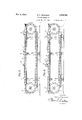
- Figure 1 is a top plan view of the conveyer mechanism.
- Fig. 2 is an enlarged transverse sectional view taken on the line 2-2 of Fig. 1.
- Fig. 3 is an enlarged longitudinal sectional view of a part of the mechanism.
- Fig. 4 is a view similar to Fig. 3 showing the mechanism at a dierent position in its operation.
- the conveyer mechanism comprises, in gen' eral, two parallel tracks 1, preferably horizontal, and a pair of endless conveyer chains 2, one arranged adiacent each track.
- the tracks l constitute, in eiect, skids upon which the articles 3 are pushed along.
- the 'articles 3 illustrated are channel bars which extend across the tracks and are adapted to be moved along the tracks. Where the channel bars 3 are in the course of fabrication into side hars for automobile frames, for instance, va-
- machines i are located at convenient points along and on opposite sides of the conveyer tracks.
- the bars 3 are pushed along the tracks i. by means of push blocks 5 arranged at predetermined spaced intervals on the endless chains 2.
- the blocks 5 extend above the upper plane or level of the tracks l and are caused to engage hars 3 as the chains 2 are moved along the tracks.
- the present invention provides a very simple means for effecting stopping of the article at the desired location adjacent each machine without stopping the conveyer chains 2.
- a stop 6 is provided on each track or rail at the desired location for stopping the article adjacent each machine.
- the stops 6 are adiustably mounted on the tracks so that they will stop the articles at any desired location for different machines.
- the stops 6 extend vertically upward on the tracks, a sufhcient height to prevent further movement of the article along the tracks except that the articles be lifted over the stops and placed on the tracks on the other side.
- the push blocks 5 In order to provide for continuous operation of the chains 2, the push blocks 5 have their forward sides inclined sufficiently to cause the article 3, when it engages stops 6, as shown in Fig.
- the inclination of the forward side of the push blocks 5 will depend upon the work at hand and also upon whether the conveyer tracks are horizontal. It should be sufficiently steep to overcome the friction in pushing the articles 3 along the tracks. On the other hand, it should be of suflciently gradual acclivity to facilitate i raising of the articles at the respective stops.
- the stops 6 may be positioned so as to stop the article at any desired angle for the operator and need not require that the article be stopped at right angles to the conveyer. ther facilitated by providing two chains 2,- one adjacent each rail. By providing rails to carry the articles thereby freeing the chains of any load, a very simple and efdcient conveyer is obtained, and one which will not require constant 105 repair and adjustment.
- a conveyeimechanism comprising a skid lie This is furlo@ for receiving and conveying articles along a predetermined path, a stop adjustably mounted on the skid to prevent further movement of an article along the skid until the article is operated upon, and constantly moving means normally below the level of said skid top having a plurality of spaced upwardly extending push blocks projecting above the level of said skid top for engaging articles on the skid and moving the articles therealong, the push blocks be-v ing adapted to pass beneath the articles when the latter engage a stop preventing their further movement along the skid.
- a conveyer mechanism comprising a skid for receiving and conveying articles along a predetermined path, a stop adjustably mounted on the skid to prevent further movement of an article along the skid until the article is operated upon, and constantly moving means having a plurality of spaced upwardly extendnig push blocks for engaging articles on the skid and mov ing the articles therealong, the push blocks having inclined forward surfaces for raising the articles when the latter engage a stop and a1- lowing the push blocks to then pass underneath the article.
Landscapes
- Engineering & Computer Science (AREA)
- Mechanical Engineering (AREA)
- Pusher Or Impeller Conveyors (AREA)
Description
Nov. 6, 1934. w. F. HEINEMAN 1,979,799
ONVEYER MECHANISM Filed Dec. 18, 1935 2 Sheets-Sheet 1 N Y N Il E WarrenFfHenemcm l ATTORNEY.
Nov. 6, 1934. w. F. HEINEMAN CONVEYER' MECHANISM Filed Deo. 18, 1953 2 Sheets-Sheet 2 INVENTOR.
Warren E' Henemcm BY' ya K5 ATTORNEY.
Fatented Non. d, i934 srares (ONVEYIER,v MECHANIISM Application December 18, 1933, Serial No. 702,840
Claims.
This invention relates to, a conveyer mechf anism and is particularly adapted for conveying 5 along the path.
'Ihe object of the invention is to provide a simple and inexpensive conveyer mechanism.
Another object is to provide a conveyer which will be continuously operating, but which, at the same time, will effect stopping of the articles being conveyed at predetermined locations.
Other objects and advantages will be pointed out hereinafter.
The accompanying drawings illustrate the preferred embodiment of the invention and the views are as follows:
Figure 1 is a top plan view of the conveyer mechanism.
Fig. 2 is an enlarged transverse sectional view taken on the line 2-2 of Fig. 1.
Fig. 3 is an enlarged longitudinal sectional view of a part of the mechanism.
Fig. 4 is a view similar to Fig. 3 showing the mechanism at a dierent position in its operation.
The conveyer mechanism comprises, in gen' eral, two parallel tracks 1, preferably horizontal, and a pair of endless conveyer chains 2, one arranged adiacent each track.
The tracks l constitute, in eiect, skids upon which the articles 3 are pushed along. The 'articles 3 illustrated are channel bars which extend across the tracks and are adapted to be moved along the tracks. Where the channel bars 3 are in the course of fabrication into side hars for automobile frames, for instance, va-
` rious machine and riveting operations must he performed upon them. For this purpose, machines i are located at convenient points along and on opposite sides of the conveyer tracks.
The bars 3 are pushed along the tracks i. by means of push blocks 5 arranged at predetermined spaced intervals on the endless chains 2. The blocks 5 extend above the upper plane or level of the tracks l and are caused to engage hars 3 as the chains 2 are moved along the tracks.
as a bar 3 comes to position adjacent an operator of a machine 4, the operator removes the bar from the tracks and carries out the desired machining or riveting operation on the bar and then replaces the bar on the tracks where it is pushed along to the position of the next machine and operator. It is not always possible for (Cl. ISS-49) all pf the operators to perform their work in the desired synchronism and in sc me instances the bar may be conveyed beyond the desired location on the tracks before the particular operator is ready to take it off from the tracks.
To overcome this difculty, the present invention provides a very simple means for effecting stopping of the article at the desired location adjacent each machine without stopping the conveyer chains 2. To this end a stop 6 is provided on each track or rail at the desired location for stopping the article adjacent each machine. The stops 6 are adiustably mounted on the tracks so that they will stop the articles at any desired location for different machines. The stops 6 extend vertically upward on the tracks, a sufhcient height to prevent further movement of the article along the tracks except that the articles be lifted over the stops and placed on the tracks on the other side. In order to provide for continuous operation of the chains 2, the push blocks 5 have their forward sides inclined sufficiently to cause the article 3, when it engages stops 6, as shown in Fig. 4, to rise and allow the blocks 5 to pass beneath, after which the article 3 drops back to the tracks 1 and remains adjacent the stops 6 until an operator lifts it oif the tracks. When the operator has completed an operation on the article 3, he places it on the tracks on the lefthand side of the stops 6 where it is again pushed along the tracks by the push blocks 5 until it reaches the next pair of stops 6.
The inclination of the forward side of the push blocks 5 will depend upon the work at hand and also upon whether the conveyer tracks are horizontal. It should be sufficiently steep to overcome the friction in pushing the articles 3 along the tracks. On the other hand, it should be of suflciently gradual acclivity to facilitate i raising of the articles at the respective stops.
The stops 6 may be positioned so as to stop the article at any desired angle for the operator and need not require that the article be stopped at right angles to the conveyer. ther facilitated by providing two chains 2,- one adjacent each rail. By providing rails to carry the articles thereby freeing the chains of any load, a very simple and efdcient conveyer is obtained, and one which will not require constant 105 repair and adjustment.
Various embodiments of the invention may be employed within the scope of the claims.
I claim:
1. A conveyeimechanism comprising a skid lie This is furlo@ for receiving and conveying articles along a predetermined path, a stop adjustably mounted on the skid to prevent further movement of an article along the skid until the article is operated upon, and constantly moving means normally below the level of said skid top having a plurality of spaced upwardly extending push blocks projecting above the level of said skid top for engaging articles on the skid and moving the articles therealong, the push blocks be-v ing adapted to pass beneath the articles when the latter engage a stop preventing their further movement along the skid.
2. A conveyer mechanism comprising a skid for receiving and conveying articles along a predetermined path, a stop adjustably mounted on the skid to prevent further movement of an article along the skid until the article is operated upon, and constantly moving means having a plurality of spaced upwardly extendnig push blocks for engaging articles on the skid and mov ing the articles therealong, the push blocks having inclined forward surfaces for raising the articles when the latter engage a stop and a1- lowing the push blocks to then pass underneath the article.
3. In combination, two parallel rails for supporting articles for movement therealong, a plurality of stops extendingupwardly from said rails and adjustably mounted thereon at predetermined locations, an endless conveyer having a plurality of spaced upwardly extending push blocks for pushing articles along said rails, and means for effecting relative vertical movement between said push blocks and an article Leraren..
when the latter engages a stop to allow said push blocks to pass beneath the article and continue their movement unobstructed while the article is stopped at the location determined by the stop.
4.. In combination, two parallel rails for rerceiving and supporting articles for movement l along 'a predetermined path, a plurality of stops extending upwardly from said rails and adjustably mounted thereon at predetermined locations, and an endless conveyer adjacent each rail having a plurality of spaced upwardly extending push blocks for pushing articles along said rails, said blocks having inclined forward faces to effect a raising of an article when the latter engages a stop and allowv the passing of the blocks beneath the article whilethe latter is retained by the stop.
5. In combination, two parallel horizontal rails, a plurality of machines arranged along either side of said rails for performing work on articles conveyed therealong, a plurality of stops extending upwardly from said rails, one stop being provided on each rail adjacent the location of each machine, an endless -chain arranged ad- .jacent each rail for continuous movement therealong in one direction and a plurality of spaced push blocks extending upwardly from each chain above the top level of the rails for pushing articles successively along said rails, said push blocks having inclined forward faces for effecting raising of the articles as they engage successive stops along the tracks and allowing the blocks to pass beneath the articles unobstructed.
WARREN F. HEINEMAN.
Priority Applications (1)
| Application Number | Priority Date | Filing Date | Title |
|---|---|---|---|
| US702840A US1979799A (en) | 1933-12-18 | 1933-12-18 | Conveyer mechanism |
Applications Claiming Priority (1)
| Application Number | Priority Date | Filing Date | Title |
|---|---|---|---|
| US702840A US1979799A (en) | 1933-12-18 | 1933-12-18 | Conveyer mechanism |
Publications (1)
| Publication Number | Publication Date |
|---|---|
| US1979799A true US1979799A (en) | 1934-11-06 |
Family
ID=24822811
Family Applications (1)
| Application Number | Title | Priority Date | Filing Date |
|---|---|---|---|
| US702840A Expired - Lifetime US1979799A (en) | 1933-12-18 | 1933-12-18 | Conveyer mechanism |
Country Status (1)
| Country | Link |
|---|---|
| US (1) | US1979799A (en) |
Cited By (3)
| Publication number | Priority date | Publication date | Assignee | Title |
|---|---|---|---|---|
| US3272308A (en) * | 1959-12-03 | 1966-09-13 | Parke Davis & Co | Mechanical loader and conveyor mechanism for handling relatively small and breakablearticles |
| US3944057A (en) * | 1974-06-24 | 1976-03-16 | Alvey, Inc. | Article propelling mechanism for conveying apparatus |
| US4361221A (en) * | 1980-10-14 | 1982-11-30 | Eastman Kodak Company | Film transporting apparatus |
-
1933
- 1933-12-18 US US702840A patent/US1979799A/en not_active Expired - Lifetime
Cited By (3)
| Publication number | Priority date | Publication date | Assignee | Title |
|---|---|---|---|---|
| US3272308A (en) * | 1959-12-03 | 1966-09-13 | Parke Davis & Co | Mechanical loader and conveyor mechanism for handling relatively small and breakablearticles |
| US3944057A (en) * | 1974-06-24 | 1976-03-16 | Alvey, Inc. | Article propelling mechanism for conveying apparatus |
| US4361221A (en) * | 1980-10-14 | 1982-11-30 | Eastman Kodak Company | Film transporting apparatus |
Similar Documents
| Publication | Publication Date | Title |
|---|---|---|
| US4465177A (en) | Elevator for a conveying system | |
| US3788497A (en) | Flow-thru palletizer and depalletizer | |
| US3469887A (en) | Apparatus for branching off floating articles | |
| GB1409391A (en) | Threedimensional operating conveyor | |
| US3659726A (en) | Palletizing apparatus | |
| KR960003629A (en) | Plate transport between drive chain and workstation | |
| US1979799A (en) | Conveyer mechanism | |
| US4732256A (en) | Storage unit for a conveyor system | |
| US1969276A (en) | Merchandise handling system | |
| US2944702A (en) | Pallet unloading machine | |
| US2514104A (en) | Conveyer mechanism | |
| US3353651A (en) | Article accumulator | |
| US2829762A (en) | Live conveyor | |
| GB1029508A (en) | Improvements in or relating to apparatus for conveying objects at different levels | |
| US2422726A (en) | Bottle conveyor | |
| US2984366A (en) | Conveyor system | |
| GB1225975A (en) | ||
| US2948386A (en) | Conveying and storing units | |
| US3090504A (en) | Apparatus for stacking slab-like elongated articles on edge | |
| ES366496A1 (en) | Variable-speed transport apparatus | |
| US3717102A (en) | Parts conveyor pallet and means for supporting same on an initial pair of rails and switching same to a second pair of rails | |
| US2530419A (en) | Can unscrambler | |
| US3512630A (en) | Live storage | |
| US2901082A (en) | Conveyor system | |
| US3520399A (en) | Flat sheet conveyer |