US1979035A - Automatic monitoring system - Google Patents
Automatic monitoring system Download PDFInfo
- Publication number
- US1979035A US1979035A US406571A US40657129A US1979035A US 1979035 A US1979035 A US 1979035A US 406571 A US406571 A US 406571A US 40657129 A US40657129 A US 40657129A US 1979035 A US1979035 A US 1979035A
- Authority
- US
- United States
- Prior art keywords
- amplifier
- signal
- output
- sound
- volume
- Prior art date
- Legal status (The legal status is an assumption and is not a legal conclusion. Google has not performed a legal analysis and makes no representation as to the accuracy of the status listed.)
- Expired - Lifetime
Links
Images


Classifications
-
- H—ELECTRICITY
- H04—ELECTRIC COMMUNICATION TECHNIQUE
- H04B—TRANSMISSION
- H04B1/00—Details of transmission systems, not covered by a single one of groups H04B3/00 - H04B13/00; Details of transmission systems not characterised by the medium used for transmission
- H04B1/62—Details of transmission systems, not covered by a single one of groups H04B3/00 - H04B13/00; Details of transmission systems not characterised by the medium used for transmission for providing a predistortion of the signal in the transmitter and corresponding correction in the receiver, e.g. for improving the signal/noise ratio
-
- H—ELECTRICITY
- H03—ELECTRONIC CIRCUITRY
- H03G—CONTROL OF AMPLIFICATION
- H03G3/00—Gain control in amplifiers or frequency changers
-
- H—ELECTRICITY
- H03—ELECTRONIC CIRCUITRY
- H03G—CONTROL OF AMPLIFICATION
- H03G3/00—Gain control in amplifiers or frequency changers
- H03G3/20—Automatic control
-
- H—ELECTRICITY
- H03—ELECTRONIC CIRCUITRY
- H03G—CONTROL OF AMPLIFICATION
- H03G5/00—Tone control or bandwidth control in amplifiers
- H03G5/16—Automatic control
- H03G5/18—Automatic control in untuned amplifiers
- H03G5/20—Automatic control in untuned amplifiers having discharge tubes
-
- H—ELECTRICITY
- H03—ELECTRONIC CIRCUITRY
- H03G—CONTROL OF AMPLIFICATION
- H03G5/00—Tone control or bandwidth control in amplifiers
- H03G5/16—Automatic control
- H03G5/18—Automatic control in untuned amplifiers
- H03G5/22—Automatic control in untuned amplifiers having semiconductor devices
-
- H—ELECTRICITY
- H03—ELECTRONIC CIRCUITRY
- H03G—CONTROL OF AMPLIFICATION
- H03G9/00—Combinations of two or more types of control, e.g. gain control and tone control
- H03G9/02—Combinations of two or more types of control, e.g. gain control and tone control in untuned amplifiers
- H03G9/04—Combinations of two or more types of control, e.g. gain control and tone control in untuned amplifiers having discharge tubes
- H03G9/10—Combinations of two or more types of control, e.g. gain control and tone control in untuned amplifiers having discharge tubes for tone control and volume expansion or compression
-
- H—ELECTRICITY
- H04—ELECTRIC COMMUNICATION TECHNIQUE
- H04R—LOUDSPEAKERS, MICROPHONES, GRAMOPHONE PICK-UPS OR LIKE ACOUSTIC ELECTROMECHANICAL TRANSDUCERS; ELECTRIC HEARING AIDS; PUBLIC ADDRESS SYSTEMS
- H04R3/00—Circuits for transducers
Definitions
- This invention relates to an automatic monitoring system, and more particularly to a system for automatically controlling the amplification ratio of an electron discharge amplifier in accordance with the volume and frequency of the
- the invention is particularly applicable to an amplifier for use with an electric phonograph pick-up or photoelectric pick-up and will be particularly described with reference thereto. It is obvious, however. that it is capable of various other uses.
- the volume of an orchestral production from full volume to low may vary as much as one hundred thousand to one, whereas the maximum ratio obtainable in a phonograph record ordinarily does not exceed one-fifth of this amount. It is evident, therefore, that the volume of the reproduced music from such record is considerably dis- 2c torted and that the true distinctions between the various sound intensities is not obtained.
- the high and low frequency tones do not maintain the same audible relation to the intermediate frequency tones.
- extraneous noises such as film noises or needle scratch, are ordinarily of comparatively high pitch and are more obvious when the signal an intensity is low and the bass notes such as a kettle drum predominate when the signal intensity is hi h.
- This invention provides means for varying the amplification of the systemin accordance with the strength of the impressed signal whereby the volume ratio is caused to approximate that of the original production.
- the invention also provides for varying the ratio of the high and low frequency notes in accordance with the output volume of the amplifier so that the higher frequencies are discriminated against when the output signal is small and the lower frequencies are discriminated against when the output signal is large.
- the invention further provides means for limiting the output of the amplifier so that the tubes, loud speaker and other equipment do not become overloaded, with consequent distortion.
- Means is also included for preventing instanto taneous operation of the monitoring system whereby the efiect of sudden percussive sounds is minimized.
- the various monitoring devices are also provided with frequency discrimination characteristics whereby the monitoring effect may be controlled both as to volume and as to frequency.
- a re- 0 sistance is inserted in the circuit with the control element of the electron discharge device and a current is passed through the resistance proportional to the average value of the intensity of the impressed signal.
- the voltage drop thus obtained 5 is caused to decrease the normal bias of the control element in accordance with the applied signal whereby the amplification characteristics of the amplifier are varied in similar proportion.
- a second resistance is inserted in the control circuit and a current is caused to pass therethrough which is proportional to the volume of the output signal when the signal exceeds a given value.
- the voltage drop of the second resistance is opposed to that in the first resistance and prevents the bias of the control element from being reduced below a predetermined value.
- a volume control tube may be inserted in the plate circuit of the electron discharge device, and utilized for cutting down the impedance external to the plate circuit 35 and thereby lowering the amplification of the electron discharge device as the output intensity increases.
- a filter is included in the input circuit of the amplifier and means is provided for varying the characteristics of the filter in accordance with the volume of the output signal. Said means is so arranged that the filter is caused to discriminate against high frequencies when the output volume is low and to discriminate against low frequencies when the output volume is high.
- the invention also consists in certain new and original features of construction and com- 1 binations of parts hereinafter set forth and claimed.
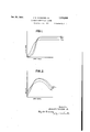
- Fig. 1 is a curve illustrating the relation between the input signal and output signal at different frequencies
- Fig. 2 is a curve illustrating the gain ratio of an amplifier. necessary to produce the relation of output signal to input signal illustrated in Fig. 1;
- Fig. 3 is a schematic diagram of an amplifying system for a phonograph pick-up constructed in accordance with the present invention
- Fig. 4 is a schematic diagram of a system for controlling the potentiometer setting.
- Fig. 5 is a schematic diagram of a modified form of the invention.
- Fig. 1 the relation between the input signal and the output signal of an amplifier operating in accordance with the present invention is illustrated. It is to be noted that for high frequencies at low intensity the output signal does not increase so rapidly with increase of input signal as does the output signal for low frequencies. This gives better proportioning of tone intensities for good quality with weak volume and further aids the elimination of scratch or stray sounds of high pitch when the volume of desired sounds is weak and scratch would otherwise be noticeable.
- the output signal is limited so that tube coupling devices and loud speakers are not overloaded.
- the overload' device may have a frequency characteristic so that low tones, for example, will cause limiting action at lower output power for low frequencies than for high frequencies.
- Fig. 2 illustrate the gain ratio of the amplifier required to produce the relation of output signal to input signal shown in Fig. 1, showing a maximum amplifier gain for output voltages of the amplifier just a little less than the maximum permissible.
- the gain ratio of the amplifier may be actuated by tone averages as well as by energy averages, so that a sustained increase in 800 cycle tone may produce an increase in the gain ratio for 100 cycles and also for 6000 cycles.
- the gain ratio in the vicinity of 100 cycles may be determined from energy only in the vicinity of 100 cycles, that for 800 cycles from energy in the vicinity of 800 cycles, and that in the vicinity of 6000 cycles from energy in the vicinity of 6000 cycles.
- FIG. 3 A schematic arrangement of an amplifier in accordance with this invention incorporating all three features, is shown in Fig. 3. It is to be understood that the circuit is adaptable to systerns in which voltages are supplied by rectifiers or other power pack devices, and with common sources for supplying plate filament and bias voltages and to systems using separate heater tubes rather than the conventional three electrode tube.
- the source of electrical currents is shown to be a phonograph pick-up device 1, and the device for converting from electrical energy to sound is the loud speaker 2 including voice and field windings 3 and 4, respectively.
- the invention is also shown as applied to a photoelectric pick-up comprising a photoelectric cell which is energized by a battery 81 and coupled with the amplifier through transformer 82.
- the photoelectric cell may be operated by light rays from light source 83 which are focused by lens 84 through an aperture 85 in plate 86 onto the sound record carried by film 87 in a manner well known in the art.
- Light source 83 may be energized from a suitable current source 88.
- Doublepole, double throw switch 89 may be used to connect the amplifiers to either phonograph pick-up 1 or photoelectric pick-up 80. It is obvious that the current may be suitably amplified before being applied to the system herein disclosed or additional output amplifiers may be employed as required.
- an amplifier including tube devices 5, 6 in cascade, followed'by tubes 7 and 8 in a push pull arrangement.
- the control of the amplifier operation is solely by the operation of tube 5, which is actuated by the weak signals from the pick-up device 1. This is controlled as to intensity characteristics by direct voltage inserted into the grid circuit of tube 5.
- Resistor 9 inserts voltage into the grid circuit depending on the intensity of input to the amplifier, determining especially the gain characteristics for low intensities. The voltage impressed here is in such a manner as to decrease the bias or potential of the control element, thereby decreasing the internal impedance of the tube.
- Resistor 10 on the other hand inserts voltage into the grid circuit depending upon the output of the amplifier, determining the characteristics for high signal intensities.
- This voltage is inserted into the grid circuit in such a manner as to increase the bias, thereby increasing the internal impedance of the tube.
- the tube is controlled as to frequency characteristics in part by the natureof the circuits supplying D. C. voltage to resistors 9 and 10, and further directly by means of variable condensers 11 and 12, which in connection with choke 13 constitute a wave filter with variable characteristics.
- This wave filter is controlled by solenoid device 14.
- the control of direct current through 9 involves an amplifier 15 actuated also from voltage source 1 prior to tube 5, so that amplified power is available fcr actuating rectifier device 18.
- a condenser 19 which in connection with the resistor 9 and the rectifier circuit controls the timing of change of voltage across resistor 9. With increasing intensity due to pick-up 1, the rectifier 18 must supply charge for increasing voltage across condenser 19, as well as for supplying the current conduction through 9, so that extremely'sudden effects may be smoothed out.
- the operation of the circuit as regards resistor 10 is quite similarto that as regards resistor 9.
- the energy for the direct current through 10 is supplied from transformer 20 subsequent to amplifier tube 5, and in this case the output transformer of the entire amplifier circuit. Energy from the output circuit is fed through windings 21 and 22 through resistors 23 and 24 and filter network 25 if desired. so that low frequency energy passes more readily than high frequency energy, and limiting action for low frequencies may occur for lower energy values in transformer 20 than for high frequencies.
- the energy passed actuates rectifier 26 which supplies direct current to resistor 10.
- a bias 27 may be supplied for the rectifier 28 so that rectification does not occur until the output voltage of the amplifier has reached a desired limit. Thus there may be no bias due to 10 whatsoever until the current through 9 has reached a considerable value.
- the current through 10 rapidly opposes the effect of current through v9 to cut down the amplification of tube 5.
- An additional filter28 may be supplied subsequent to rectification to cut down on any residual audio tone currents which might otherwise get into the grid circuit of tube 5.
- the channel for control of frequency characteristics of gain of tube 5 is also shown as controlled by output power of the entire amplifier.
- This control may be from windings 21 and 22 which supply control current for resistor 10, a separate winding may be used however.
- control power passes through resistors 29 and 30, actuating rectifier 31 which produces direct voltage across condenser 32 and resistor 33 which are included in the grid circuit of three electrode rectifier 34, the plate circuit of which is actuated by an A. C. source 35 operating through transformer 36.
- the impedance of the rectifier 34 is controlled by the bias on the rectifier control circuit due to current in resistor 33, and with large intensities in the amplifier output circuit, the impedance of the tube is low and large currents are rectified by device 34.
- the rectified output is filtered by devices 37 and passes through the windings of solenoid 14, the plunger of which drives variable condensers 11 and 12.
- the action will normally be such that increased intensities in the output lower the capacities of the condensers, thereby permitting high notes to pass well, but with the intensity of output weak, the capacity of condensers 11 and 12 will be increased, with nearly complete elimination of scratch or other high frequency sounds not desired.
- tube 5 is adjusted by means of potentiometer 38 to give a low reading of meter 39 with pick-up device 1 inoperative. Then with weak and low intensities, the bias thrown into the circuit by resistor 9 increases the reading of 39, because of the lessened bias. For higher intensities, the reading of the meter diminishes because of the reverse bias due to resistor 10.
- a bias control which may be used if desired is shown in Fig. 4, in which the meter 39 is of a relay type so that the bias due to potentiometer 38 will set itself automatically to cause the tube to pass a certain amount of current.
- a contact 39a which is closed when the meter currentislessthanthe desired minimum amount. This contact operates a controller device 395 to move the potentiometer 38 until the plate current exceeds the desired minimum value, when no further change will be produced.
- Fig. 5 shows a modified form of monitoring system for controlling the amplification of signals derived from phonograph pick-up 1, amplified by tubes 5, 6, '7 and 8 and applied to loud speaker 2.
- the various elements which are similar to those shown in Fig. 3 have been given similar reference numerals.
- the grid potential of tube 5 is controlled by the current passed through resistance 9, which varies in response to variations in the applied signal. This is opposed for high signal outputs by the current in resistance 10 in the manner described in connection with Fig. 3.
- V voltage
- the grid circuit of tube 5 is provided with a high resistance 40, for example, 5 megohms shunted by by-pass condenser 41 having a capacity, for example, of .1 mf.
- the current drawn in the grid circuit of tube 5 when a large signal is impressed causes a potential drop in resistance 40 which prevents an abnormal reduction in the grid pofiential, thereby avoiding an overload of the tu e.
- a volume control tube 42 in the plate circuit of tube 5.
- the impedance of tube 42 is controlled by the current fiowing through resistance 60 which is included in the grid circuit thereof.
- the current in resistance 60 is controlled in accordance with the output signal through secondary winding 61 of transformer 20 which is connected through a filter 62 to a rectifying device 63.
- Rectifying device 63 may have a source of biasing potential 64 associated therewith to prevent the device from operating when the output signal falls below a given intensity. With signals above this given intensity a current is produced in resistance 60 which lowers the impedance of tube 42, thereby cutting down the impedance external to the plate circuit of tube 5 and lowering the amplification of the system as the output intensity increases.
- the impedance of tube 42 is also controlled by the voltage drop in resistance 71 in the plate circuit thereof which operates to vary the impedance in accordance with the current flowing in said plate circuit.
- the circuit for controlling tone on high intensities and low intensities is of a vacuum tube control type instead of the electro-mechanical type shown in Fig. 3.
- tubes 43 and 44 are in series with filter condensers 45 and 46 respectively from terminals of choke 13 to grid return circuit of tube 5.
- the plates of these tubes are shunt fed by suitable high impedance chokes 47 and 48.
- the impedance of the tubes from plate to filament is controlled by bias resistor 49 and condenser 50, which are supplied by direct current derived from the final amplifier output.
- Potentiometer may be connected in the grid circuit of-amplifier tube 6 to provide a manual volume control which operates solely on the output current and does not interfere with the efiicient operation of the automatic monitoring system.
- the amplification characteristics of amplifying tube 5 is primarily controlled by the potential drop in resistance 9. This varies in accordance with the strength of the impressed i signal whereby the amplification ratio of the tube is increased for large signals and decreased for weak signals.
- a suitable filter net work 1'7 is provided which preferably discriminates against high frequencies so that extraneous noises of high '1 pitch, such as needle scratch and film noises, will be largely suppressed when the signal intensity is low.
- the potential drop in resistance 10 is utilized for preventing the output volume from becoming excessive and also for preventing predominant notes of low frequency from afiecting the operation of the system. This is accomplished as above pointed out by causing a current to fiow in resistance 10 which is proportional to the strength of the output signal when the output signal exceeds a given minimum, thereby increasing the bias of tube 5 and cutting down its output current. Filter net work 25 is made to discriminate against low frequency notes so that the predominant eifect of such notes at high intensity is minimized.
- Condenser 19 which is connected across resistance 9, introduces a time delay into the control circuit and prevents the current in resistance 9 from changing in response to instantaneous changes in input signal intensity. This also prevents a sudden concussion, .such as the sound of a kettle drum, from disrupting the entire system.
- Tube 42 which is connected in the plate circuit of tube 5,-serves as a further limiting device and is operated in response to high intensity output signals for limiting the amplification of the entire system. 7
- variable impedance filter net work comprising condensers 11 and 12 in Fig. 3 and tubes selection, in substantially its true ratio of intensity and tone.
- control havebeerr disclosed as applied to the various tubes for determining their amplification characteristics. It is obvious. however, that other control systems may be employed if desired without departing from the present invention.
- an automatic control system therefor comprising means controlled by the signal strength for varying the amplification characteristics of said amplifier in accordance with the strength of the impressed signal, and means controlled by the output volume for preventing said amplifier from being overloaded when strong signals are applied thereto.
- an automatic control system comprising means controlled by the strength of signal for causing said amplifier to discriminate against high frequencies when the signal strength is small and against low frequencies when the signal strength is large.
- an automatic control system comprising means controlled'by the strength of signal for causing said amplifier to discriminate against high frequencies when the signal strength is small.
- an automatic control system comprising means controlled by the strength of signal for causing said amplifier to discriminate against low frequencies when the signal strength is large.
- an automatic control system comprising means controlled by the signal strength for varying the amplification characteristics of said amplifier in accordance with the strength of the impressed signal, and means controlled by the output volume for varying the amplification characteristics of said amplifier inversely as the output volume of said amplifier when said output volume exceeds a predetermined value.
- an electron discharge amplifying system including an electron discharge device, an automatic control system comprising 'means controlled by the signal strength for decreasing the internal impedance of said devieednversely as the signal strength until the output volume reaches a predetermined value and means controlled by the output volume for increasing said impedance when the output signal exceeds said predetermined value.
- an electron discharge amplifying system including an electron discharge device having a control element, an automatic control system comprising means controlled by the signal strength for decreasing the bias of said element in accordance with the strength of the input signal until the output volume reaches a predetermined value, and means controlled by the output volume for increasing said bias when the output signal exceeds said predetermined value.
- an amplifying system including an electron discharge device having a control element, a resistance included in the circuit of said control element, means controlled by the signal strength for passing a direct current through said resistance varying in accordance with the volume of the input signal, a second resistance in the circuit of said control element, and means controlled by the output volume for causing a direct current to pass through said second resistance varying in accordance with the output volume of said amplifier, said resistances being so arranged 80 that the voltage drops produced therein are in mutually opposing relationship.
- a filter in the input circuit thereof, and means controlled by the signal strength for varying the characteristics of said filter in accordance with the signal intensity in the output circuit of said amplifier whereby said filter is caused to discriminate against high frequencies when the output intensity is low and to discriminate against low frequencies when the output intensity is high, and a limiting device included in said amplifier and controlled by the intensity of the output signal to limit said signal to a predetermined value.
- a filter in the input circuit thereof having a variable impedance, and means controlled by the signal strength for varying the impedance of said filter in accordance with the signal intensity of said amplifier whereby said filter is caused to discriminate against high frequencies when the output intensity is low and to discriminate against low frequencies when the output intensity is high, said means comprising a solenoid associated with said variable impedance and operated in accordance with the signal strength in the output circuit of said amplifying system.
- a filter in the input circuit thereof including a variable impedance space discharge device, and means controlled by the signal strength for varying the impedance of said device in accordance with the signal intensity in the output circuit of said amplifier so that said filter is caused to discriminate against high frequencies when the outputintensity is low and discriminate against low frequencies when the output intensity is high.
- a system for reproducing sound from a record including an electric pick-up, an amplifying system therefor and a sound propagating device associated therewith, means controlled by the signal strength for automatically controlling the amplification characteristics in accordance with the strength of the impressed signals whereby the volume ratio between strong and weak signals in the sound propagating device exceeds the volume ratio produced by the electrical pickup, and means controlled by the output volume for limiting the amplification characteristics of said amplifier when the output signal exceeds a predetermined value whereby the rated capacity of said system will not be exceeded.
- an automatic control system comprising means controlled by the signal intensity for causing said amplifier to discriminate against high frequency tones when the signal intensity is low whereby the effect of needle scratch, film noises and other extraneous noises is reduced.
- an automatic control system comprising means controlled by the signal intensity for causing said amplifier to discriminate against low frequency tones when the signal intensity is high.
- a main amplifier means for impressing energy due to the sound variations from said record on said amplifier, means for controlling the gain ratio of said amplifier by and in accordance with the changes in the average intensity of the sound energy obtained from said record in such manner that the gain ratio of the amplifier increases with increase in input sound no strength up to a given limiting value within the capacity of the amplifier and means whereby the gain ratio of said amplifier decreases with further increase in input sound strength.
- a sound record In a sound reproducing system, a sound record, a pick-up device therefor, a sound propagating device fed by said pick-up device, and means controlled by variations in the signal volume picked up by said pick-up device for varying the discrimination against undesired tone frequencies.
- a sound record In a sound reproducing system, a sound record, a pick-up device therefor, a sound propagating device fed by said pick-up device, and means controlled by variations in the signal volume received from said pick-up device for discriminating against high frequency notes with small signal volume and against low frequency notes with large signal volume.
- a sound 130 record a pick-up device therefor, a sound propagating device fed by said pick-up device, and means controlled by variations in the signal volume received from said pick-up device for discriminating against high frequency notes with 5 small signal volume.
- a sound record In a sound reproducing system, a sound record, a pick-up device therefor, a sound propagating device fed by said pick-up device, and means controlled by the variations in signal 1 volume received from said pick-up device for discriminating against low frequency notes with large signal volume.
- a sound reproducing system a sound record, a pick-up device therefor, a dynamic ex- 145 panding amplifier fed by said pick-up device, a sound propagating device fed by said amplifier, a variable load fed by said amplifier, and means controlled by the output of said amplifier for determining the value of said load.
- a sound record In a sound reproducing system, a sound record, a pick-up device therefor, a dynamic amplifier fed by said pick-up device, a sound propagating device fed by said amplifier, a control device fed by the output of said amplifier and responsive only to low frequency tones for limiting the gain ratio of said amplifier.
- a sound record In a sound reproducing system, a sound record, a pick-up device therefor, a variable filter fed by said pick-up device, a sound propagating device fed by said filter, and means controlled by variations in the volume of low frequency tones only for varying the frequencies passed by said filter.
- a sound record In a sound reproducing system, a sound record, a pick-up device therefor, a variable filter fed by said pick-up device, a sound propagating device fed by said filter, and a control device fed by said filter and responsive to low frequency times only for operating the variable filter to pass more freely the higher frequencies when the low frequency tones are strong and to pass more freely the lower frequencies when the low frequency tones are weak.
- a sound record In a sound reproducing system, a sound record, a pickup device therefor, a variable filter fed by said pick-up device, a sound propagating device fed by said filter, and means controlled by the amount of energy from said pick-up device for varying the frequency transmission characteristics of said filter.
Landscapes
- Engineering & Computer Science (AREA)
- Signal Processing (AREA)
- Computer Networks & Wireless Communication (AREA)
- Physics & Mathematics (AREA)
- Acoustics & Sound (AREA)
- Amplifiers (AREA)
- Networks Using Active Elements (AREA)
Description
Cd. 30, 1934. J M 41 1,979,035
AUTOMATIC MONITORING SYSTEM Filed Nov. 12, 1929 3 Sheets-Sheet l FIGJ.-
BOOON 600w \NPUT SIGNAL 6000- Q E \OOrv \NPUT S1GNAL avwentoz JOHN HAYS HAMMOND JR. abtomwl Oct. 30, 1934. H, HAMMQND' JR 1,979,035
AUTOMATIC MONITORING SYSTEM Filed Nov. 12. 1929 3 Sheets-Sheet 2 JOHN HAYS HAMMONDJR 351 flbto'vn v itaienied @ct. 30, 1934 STATES PATENT OFFICE AUTOMATIC MONITORING SYSTEM Application November 12, 1929, Serial No. 406,571
Claim. (01. ire-100.4)
This invention relates to an automatic monitoring system, and more particularly to a system for automatically controlling the amplification ratio of an electron discharge amplifier in accordance with the volume and frequency of the The invention is particularly applicable to an amplifier for use with an electric phonograph pick-up or photoelectric pick-up and will be particularly described with reference thereto. It is obvious, however. that it is capable of various other uses. I The volume of an orchestral production from full volume to low may vary as much as one hundred thousand to one, whereas the maximum ratio obtainable in a phonograph record ordinarily does not exceed one-fifth of this amount. It is evident, therefore, that the volume of the reproduced music from such record is considerably dis- 2c torted and that the true distinctions between the various sound intensities is not obtained. Furthermore, when the intensity of the signals in a phonograph amplifier or other sound producing device is high or low, the high and low frequency tones do not maintain the same audible relation to the intermediate frequency tones. For example, extraneous noises, such as film noises or needle scratch, are ordinarily of comparatively high pitch and are more obvious when the signal an intensity is low and the bass notes such as a kettle drum predominate when the signal intensity is hi h.
This invention provides means for varying the amplification of the systemin accordance with the strength of the impressed signal whereby the volume ratio is caused to approximate that of the original production.
The invention also provides for varying the ratio of the high and low frequency notes in accordance with the output volume of the amplifier so that the higher frequencies are discriminated against when the output signal is small and the lower frequencies are discriminated against when the output signal is large.
The invention further provides means for limiting the output of the amplifier so that the tubes, loud speaker and other equipment do not become overloaded, with consequent distortion.
Means is also included for preventing instanto taneous operation of the monitoring system whereby the efiect of sudden percussive sounds is minimized. The various monitoring devices are also provided with frequency discrimination characteristics whereby the monitoring effect may be controlled both as to volume and as to frequency.
This is accomplished in accordance with the present invention by providing means for varying the impedance of one of the electron discharge amplifiers in accordance with the volume of the input and output signals. For this purpose a re- 0 sistance is inserted in the circuit with the control element of the electron discharge device and a current is passed through the resistance proportional to the average value of the intensity of the impressed signal. The voltage drop thus obtained 5 is caused to decrease the normal bias of the control element in accordance with the applied signal whereby the amplification characteristics of the amplifier are varied in similar proportion.
In order to prevent the output signal from ris- 7o ing to a volume which would overload the amplifier and cause distortion, a second resistance is inserted in the control circuit and a current is caused to pass therethrough which is proportional to the volume of the output signal when the signal exceeds a given value. The voltage drop of the second resistance is opposed to that in the first resistance and prevents the bias of the control element from being reduced below a predetermined value.
As a further means for preventing overload in the output circuit amplifier, a volume control tube may be inserted in the plate circuit of the electron discharge device, and utilized for cutting down the impedance external to the plate circuit 35 and thereby lowering the amplification of the electron discharge device as the output intensity increases.
In order to control the ratio of amplification for different tone frequencies, a filter is included in the input circuit of the amplifier and means is provided for varying the characteristics of the filter in accordance with the volume of the output signal. Said means is so arranged that the filter is caused to discriminate against high frequencies when the output volume is low and to discriminate against low frequencies when the output volume is high.
The invention also consists in certain new and original features of construction and com- 1 binations of parts hereinafter set forth and claimed.
Although the novel features which are believed to be characteristic of this invention will be particularly pointed out in the claims appended hereto, the invention itself, as to its objects and advantages, the mode of its operation and the manner of its organization may be better understood by referring to the following description taken in connection with the accompanying drawings forming a part thereof, in which Fig. 1 is a curve illustrating the relation between the input signal and output signal at different frequencies;
Fig. 2 is a curve illustrating the gain ratio of an amplifier. necessary to produce the relation of output signal to input signal illustrated in Fig. 1;
Fig. 3 is a schematic diagram of an amplifying system for a phonograph pick-up constructed in accordance with the present invention;
Fig. 4 is a schematic diagram of a system for controlling the potentiometer setting; and
Fig. 5 is a schematic diagram of a modified form of the invention.
Like reference characters denote like parts in the several figures of the drawings.
In the following description and in the claims parts will be identified by specific names for convenience, but they are intended to be as generic in their application to simflar parts as the art will permit.
Referring to Fig. 1, the relation between the input signal and the output signal of an amplifier operating in accordance with the present invention is illustrated. It is to be noted that for high frequencies at low intensity the output signal does not increase so rapidly with increase of input signal as does the output signal for low frequencies. This gives better proportioning of tone intensities for good quality with weak volume and further aids the elimination of scratch or stray sounds of high pitch when the volume of desired sounds is weak and scratch would otherwise be noticeable. At high input intensities, the output signal is limited so that tube coupling devices and loud speakers are not overloaded. The overload' device may have a frequency characteristic so that low tones, for example, will cause limiting action at lower output power for low frequencies than for high frequencies.
The curves of Fig. 2 illustrate the gain ratio of the amplifier required to produce the relation of output signal to input signal shown in Fig. 1, showing a maximum amplifier gain for output voltages of the amplifier just a little less than the maximum permissible.
Distortion due to curvature of characteristics is prevented by the use of time lag and time average devices. The curves shown do not represent instantaneous characteristics as do usual curves of vacuum discharge tubes, but the change of gain ratio requires time and sustained effect.
Further, in some of the simpler types of instruments in accordance with this invention, the gain ratio of the amplifier may be actuated by tone averages as well as by energy averages, so that a sustained increase in 800 cycle tone may produce an increase in the gain ratio for 100 cycles and also for 6000 cycles. In more complex apparatus, however, the gain ratio in the vicinity of 100 cycles may be determined from energy only in the vicinity of 100 cycles, that for 800 cycles from energy in the vicinity of 800 cycles, and that in the vicinity of 6000 cycles from energy in the vicinity of 6000 cycles.
A schematic arrangement of an amplifier in accordance with this invention incorporating all three features, is shown in Fig. 3. It is to be understood that the circuit is adaptable to systerns in which voltages are supplied by rectifiers or other power pack devices, and with common sources for supplying plate filament and bias voltages and to systems using separate heater tubes rather than the conventional three electrode tube.
In this arrangement, the source of electrical currents is shown to be a phonograph pick-up device 1, and the device for converting from electrical energy to sound is the loud speaker 2 including voice and field windings 3 and 4, respectively.
The invention is also shown as applied to a photoelectric pick-up comprising a photoelectric cell which is energized by a battery 81 and coupled with the amplifier through transformer 82. The photoelectric cell may be operated by light rays from light source 83 which are focused by lens 84 through an aperture 85 in plate 86 onto the sound record carried by film 87 in a manner well known in the art. Light source 83 may be energized from a suitable current source 88. Doublepole, double throw switch 89 may be used to connect the amplifiers to either phonograph pick-up 1 or photoelectric pick-up 80. It is obvious that the current may be suitably amplified before being applied to the system herein disclosed or additional output amplifiers may be employed as required.
Interposed between switch 89 and loud speaker 2 is an amplifier including tube devices 5, 6 in cascade, followed'by tubes 7 and 8 in a push pull arrangement. The control of the amplifier operation is solely by the operation of tube 5, which is actuated by the weak signals from the pick-up device 1. This is controlled as to intensity characteristics by direct voltage inserted into the grid circuit of tube 5. Resistor 9 inserts voltage into the grid circuit depending on the intensity of input to the amplifier, determining especially the gain characteristics for low intensities. The voltage impressed here is in such a manner as to decrease the bias or potential of the control element, thereby decreasing the internal impedance of the tube. Resistor 10 on the other hand inserts voltage into the grid circuit depending upon the output of the amplifier, determining the characteristics for high signal intensities. This voltage is inserted into the grid circuit in such a manner as to increase the bias, thereby increasing the internal impedance of the tube. The tube is controlled as to frequency characteristics in part by the natureof the circuits supplying D. C. voltage to resistors 9 and 10, and further directly by means of variable condensers 11 and 12, which in connection with choke 13 constitute a wave filter with variable characteristics. This wave filter is controlled by solenoid device 14.
The control of direct current through 9 involves an amplifier 15 actuated also from voltage source 1 prior to tube 5, so that amplified power is available fcr actuating rectifier device 18. Interposed between the tube and rectifier is a transformer 16 and suitable filter network 17, whereby if desired, high pitch electrical tones originating in device 1 actuate device 18 more easily than low pitch electrical tones. Across the output of the rectifier is incorporated a condenser 19 which in connection with the resistor 9 and the rectifier circuit controls the timing of change of voltage across resistor 9. With increasing intensity due to pick-up 1, the rectifier 18 must supply charge for increasing voltage across condenser 19, as well as for supplying the current conduction through 9, so that extremely'sudden effects may be smoothed out. Similarly when the intensity due to 1 is reduced, the voltage across 9 does not drop immediately because when less charge is supplied by rectifier 18, the condenser 19 discharges through resistor 9. A further function of condenser 19 is to prevent any tone frequency from being present in 9, thereby avoiding.all eil'ects other than change of bias on the tube.
The operation of the circuit as regards resistor 10 is quite similarto that as regards resistor 9. The energy for the direct current through 10 is supplied from transformer 20 subsequent to amplifier tube 5, and in this case the output transformer of the entire amplifier circuit. Energy from the output circuit is fed through windings 21 and 22 through resistors 23 and 24 and filter network 25 if desired. so that low frequency energy passes more readily than high frequency energy, and limiting action for low frequencies may occur for lower energy values in transformer 20 than for high frequencies. The energy passed actuates rectifier 26 which supplies direct current to resistor 10. A bias 27 may be supplied for the rectifier 28 so that rectification does not occur until the output voltage of the amplifier has reached a desired limit. Thus there may be no bias due to 10 whatsoever until the current through 9 has reached a considerable value. For higher inputs, the current through 10 rapidly opposes the effect of current through v9 to cut down the amplification of tube 5. An additional filter28 may be supplied subsequent to rectification to cut down on any residual audio tone currents which might otherwise get into the grid circuit of tube 5.
The channel for control of frequency characteristics of gain of tube 5 is also shown as controlled by output power of the entire amplifier. This control may be from windings 21 and 22 which supply control current for resistor 10, a separate winding may be used however. As shown, control power passes through resistors 29 and 30, actuating rectifier 31 which produces direct voltage across condenser 32 and resistor 33 which are included in the grid circuit of three electrode rectifier 34, the plate circuit of which is actuated by an A. C. source 35 operating through transformer 36. The impedance of the rectifier 34 is controlled by the bias on the rectifier control circuit due to current in resistor 33, and with large intensities in the amplifier output circuit, the impedance of the tube is low and large currents are rectified by device 34. The rectified output is filtered by devices 37 and passes through the windings of solenoid 14, the plunger of which drives variable condensers 11 and 12. The action will normally be such that increased intensities in the output lower the capacities of the condensers, thereby permitting high notes to pass well, but with the intensity of output weak, the capacity of condensers 11 and 12 will be increased, with nearly complete elimination of scratch or other high frequency sounds not desired.
' The operation of tube 5 is adjusted by means of potentiometer 38 to give a low reading of meter 39 with pick-up device 1 inoperative. Then with weak and low intensities, the bias thrown into the circuit by resistor 9 increases the reading of 39, because of the lessened bias. For higher intensities, the reading of the meter diminishes because of the reverse bias due to resistor 10.
A bias control which may be used if desired is shown in Fig. 4, in which the meter 39 is of a relay type so that the bias due to potentiometer 38 will set itself automatically to cause the tube to pass a certain amount of current. Here there is a contact 39a which is closed when the meter currentislessthanthe desired minimum amount. This contact operates a controller device 395 to move the potentiometer 38 until the plate current exceeds the desired minimum value, when no further change will be produced.
Fig. 5 shows a modified form of monitoring system for controlling the amplification of signals derived from phonograph pick-up 1, amplified by tubes 5, 6, '7 and 8 and applied to loud speaker 2. The various elements which are similar to those shown in Fig. 3 have been given similar reference numerals. The grid potential of tube 5 is controlled by the current passed through resistance 9, which varies in response to variations in the applied signal. This is opposed for high signal outputs by the current in resistance 10 in the manner described in connection with Fig. 3. V
For preventing overload of the amplifying system, the grid circuit of tube 5 is provided with a high resistance 40, for example, 5 megohms shunted by by-pass condenser 41 having a capacity, for example, of .1 mf. The current drawn in the grid circuit of tube 5 when a large signal is impressed causes a potential drop in resistance 40 which prevents an abnormal reduction in the grid pofiential, thereby avoiding an overload of the tu e.
For further controlling the amplification with loud output signals there is provided a volume control tube 42 in the plate circuit of tube 5. The impedance of tube 42 is controlled by the current fiowing through resistance 60 which is included in the grid circuit thereof. The current in resistance 60 is controlled in accordance with the output signal through secondary winding 61 of transformer 20 which is connected through a filter 62 to a rectifying device 63. Rectifying device 63 may have a source of biasing potential 64 associated therewith to prevent the device from operating when the output signal falls below a given intensity. With signals above this given intensity a current is produced in resistance 60 which lowers the impedance of tube 42, thereby cutting down the impedance external to the plate circuit of tube 5 and lowering the amplification of the system as the output intensity increases.
The impedance of tube 42 is also controlled by the voltage drop in resistance 71 in the plate circuit thereof which operates to vary the impedance in accordance with the current flowing in said plate circuit.
The circuit for controlling tone on high intensities and low intensities is of a vacuum tube control type instead of the electro-mechanical type shown in Fig. 3. Here tubes 43 and 44 are in series with filter condensers 45 and 46 respectively from terminals of choke 13 to grid return circuit of tube 5. The plates of these tubes are shunt fed by suitable high impedance chokes 47 and 48. The impedance of the tubes from plate to filament is controlled by bias resistor 49 and condenser 50, which are supplied by direct current derived from the final amplifier output.
When a large intensity of signal occurs in the output to the loud speaker, current passes through resistor 49 in such a manner as to decrease the A. C. conduction of tube 43 and therefore the A. C. conduction through condenser 45 to the grid return circuit of tube 5. Tube 44 similarly controls the conduction through condenser 46. As a result on weak signals, the filter network comprising chokes 13, 47, 48, condensers 45 and 46, and tubes 43 and 44 automatically changes with signal strength tocut out high tones on weak 150 output signals, thereby reducing scratch disturbances most under the conditions for which they are most objectionable.
Current is applied to resistor 49 through a suitable rectifier and filter net work 86 associated with resistances 29 and 30' which are connected to the output circuit amplifier in the manner pointed out in connection with Fig. 3.
Potentiometer may be connected in the grid circuit of-amplifier tube 6 to provide a manual volume control which operates solely on the output current and does not interfere with the efiicient operation of the automatic monitoring system.
In the preceding description various devices have been referred to as tubes, but it is obvious that any type of electron discharge device may be employed. Furthermore, the rectifiers have been shown as tubes for purpose of illustration only and are not to be limited thereto. The various electron discharge devices have associated therewith suitable sources of potential which are connected in the manner well known in the art and which accordingly have not been described in detafl.
' In the operation of the above-described monitoring system the amplification characteristics of amplifying tube 5 is primarily controlled by the potential drop in resistance 9. This varies in accordance with the strength of the impressed i signal whereby the amplification ratio of the tube is increased for large signals and decreased for weak signals. A suitable filter net work 1'7 is provided which preferably discriminates against high frequencies so that extraneous noises of high '1 pitch, such as needle scratch and film noises, will be largely suppressed when the signal intensity is low.
The potential drop in resistance 10 is utilized for preventing the output volume from becoming excessive and also for preventing predominant notes of low frequency from afiecting the operation of the system. This is accomplished as above pointed out by causing a current to fiow in resistance 10 which is proportional to the strength of the output signal when the output signal exceeds a given minimum, thereby increasing the bias of tube 5 and cutting down its output current. Filter net work 25 is made to discriminate against low frequency notes so that the predominant eifect of such notes at high intensity is minimized.
The variable impedance filter net work, comprising condensers 11 and 12 in Fig. 3 and tubes selection, in substantially its true ratio of intensity and tone.
Certain types of control havebeerr disclosed as applied to the various tubes for determining their amplification characteristics. It is obvious. however, that other control systems may be employed if desired without departing from the present invention.
While certain novel features of the invention have been shown and described and are pointed out in the annexed claims, it will be understood that various omissions, substitutions and changes in the form and details of the device illustrated and in its operation may be made by those skilled in the art without departing from the spirit of the, invention.
What is claimed is:
1. In a system for reproducing sound from a sound record an electron discharge amplifier, an automatic control system therefor comprising means controlled by the signal strength for varying the amplification characteristics of said amplifier in accordance with the strength of the impressed signal, and means controlled by the output volume for preventing said amplifier from being overloaded when strong signals are applied thereto.
2. In a system for reproducing sound from a sound record an electron discharge amplifier, an automatic control system therefor comprising means controlled by the strength of signal for causing said amplifier to discriminate against high frequencies when the signal strength is small and against low frequencies when the signal strength is large.
3. In a system for reproducing sound from a sound record an electron discharge amplifier, an automatic control system therefor comprising means controlled'by the strength of signal for causing said amplifier to discriminate against high frequencies when the signal strength is small.
4. In a system for reproducing sound from a sound record an electron discharge amplifier, an automatic control system therefor comprising means controlled by the strength of signal for causing said amplifier to discriminate against low frequencies when the signal strength is large.
5. In a system for reproducing sound from a sound record an electron discharge amplifier, an automatic control system therefor comprising means controlled by the signal strength for varying the amplification characteristics of said amplifier in accordance with the strength of the impressed signal, and means controlled by the output volume for varying the amplification characteristics of said amplifier inversely as the output volume of said amplifier when said output volume exceeds a predetermined value.
6. In a system for reproducing sound from a sound record an electron discharge amplifying system including an electron discharge device, an automatic control system comprising 'means controlled by the signal strength for decreasing the internal impedance of said devieednversely as the signal strength until the output volume reaches a predetermined value and means controlled by the output volume for increasing said impedance when the output signal exceeds said predetermined value.
'7. In a system for reproducing sound from a sound record an electron discharge amplifying controlled bythe signal strength for controlling said filter system whereby said amplifier discriminates against high frequencies when the signal volume is low and discriminates against low frequencies when the signal volume is high.
8. In a system for reproducing sound from a sound record an electron discharge amplifying system including an electron discharge device having a control element, an automatic control system comprising means controlled by the signal strength for decreasing the bias of said element in accordance with the strength of the input signal until the output volume reaches a predetermined value, and means controlled by the output volume for increasing said bias when the output signal exceeds said predetermined value.
9. In a system for reproducing sound from a sound record an amplifying system including an electron discharge device having a control element, a resistance included in the circuit of said control element, means controlled by the signal strength for passing a direct current through said resistance varying in accordance with the volume of the input signal, a second resistance in the circuit of said control element, and means controlled by the output volume for causing a direct current to pass through said second resistance varying in accordance with the output volume of said amplifier, said resistances being so arranged 80 that the voltage drops produced therein are in mutually opposing relationship.
10. In a system for reproducing sound from a sound record an amplifying system, a filter in the input circuit thereof, and means controlled by the signal strength for varying the characteristics of said filter in accordance with the signal intensity in the output circuit of said amplifier whereby said filter is caused to discriminate against high frequencies when the output intensity is low and to discriminate against low frequencies when the output intensity is high, and a limiting device included in said amplifier and controlled by the intensity of the output signal to limit said signal to a predetermined value.
11. In a system for reproducing sound from a sound record an amplifying system, a filter in the input circuit thereof having a variable impedance, and means controlled by the signal strength for varying the impedance of said filter in accordance with the signal intensity of said amplifier whereby said filter is caused to discriminate against high frequencies when the output intensity is low and to discriminate against low frequencies when the output intensity is high, said means comprising a solenoid associated with said variable impedance and operated in accordance with the signal strength in the output circuit of said amplifying system.
12. In a system for reproducing sound from a sound record an amplifying system, a filter in the input circuit thereof including a variable impedance space discharge device, and means controlled by the signal strength for varying the impedance of said device in accordance with the signal intensity in the output circuit of said amplifier so that said filter is caused to discriminate against high frequencies when the outputintensity is low and discriminate against low frequencies when the output intensity is high.
13. In a system for reproducing sound from a record including an electric pick-up, an amplifying system therefor and a sound propagating device associated therewith, means controlled by the signal strength for automatically controlling the amplification characteristics in accordance with the strength of the impressed signals whereby the volume ratio between strong and weak signals in the sound propagating device exceeds the volume ratio produced by the electrical pickup, and means controlled by the output volume for limiting the amplification characteristics of said amplifier when the output signal exceeds a predetermined value whereby the rated capacity of said system will not be exceeded.
14.-In a system for reproducing sound from a record including a pick-up device, an amplifier and a sound propagating device, an automatic control system comprising means controlled by the signal intensity for causing said amplifier to discriminate against high frequency tones when the signal intensity is low whereby the effect of needle scratch, film noises and other extraneous noises is reduced.
15. In a system for reproducing sound from a record including a pick-up device, an amplifier and a sound propagating device, an automatic control system comprising means controlled by the signal intensity for causing said amplifier to discriminate against low frequency tones when the signal intensity is high.
16. In an amplifying system for use with a sound record, a main amplifier, means for impressing energy due to the sound variations from said record on said amplifier, means for controlling the gain ratio of said amplifier by and in accordance with the changes in the average intensity of the sound energy obtained from said record in such manner that the gain ratio of the amplifier increases with increase in input sound no strength up to a given limiting value within the capacity of the amplifier and means whereby the gain ratio of said amplifier decreases with further increase in input sound strength.
17. In a sound reproducing system, a sound record, a pick-up device therefor, a sound propagating device fed by said pick-up device, and means controlled by variations in the signal volume picked up by said pick-up device for varying the discrimination against undesired tone frequencies.
18. In a sound reproducing system, a sound record, a pick-up device therefor, a sound propagating device fed by said pick-up device, and means controlled by variations in the signal volume received from said pick-up device for discriminating against high frequency notes with small signal volume and against low frequency notes with large signal volume.
19. In a sound reproducing system, a sound 130 record, a pick-up device therefor, a sound propagating device fed by said pick-up device, and means controlled by variations in the signal volume received from said pick-up device for discriminating against high frequency notes with 5 small signal volume.
20. In a sound reproducing system, a sound record, a pick-up device therefor, a sound propagating device fed by said pick-up device, and means controlled by the variations in signal 1 volume received from said pick-up device for discriminating against low frequency notes with large signal volume.
21. In a sound reproducing system, a sound record, a pick-up device therefor, a dynamic ex- 145 panding amplifier fed by said pick-up device, a sound propagating device fed by said amplifier, a variable load fed by said amplifier, and means controlled by the output of said amplifier for determining the value of said load.
22. In a sound reproducing system, a sound record, a pick-up device therefor, a dynamic amplifier fed by said pick-up device, a sound propagating device fed by said amplifier, a control device fed by the output of said amplifier and responsive only to low frequency tones for limiting the gain ratio of said amplifier.
23. In a sound reproducing system, a sound record, a pick-up device therefor, a variable filter fed by said pick-up device, a sound propagating device fed by said filter, and means controlled by variations in the volume of low frequency tones only for varying the frequencies passed by said filter.
24. In a sound reproducing system, a sound record, a pick-up device therefor, a variable filter fed by said pick-up device, a sound propagating device fed by said filter, and a control device fed by said filter and responsive to low frequency times only for operating the variable filter to pass more freely the higher frequencies when the low frequency tones are strong and to pass more freely the lower frequencies when the low frequency tones are weak.
25. In a sound reproducing system, a sound record, a pickup device therefor, a variable filter fed by said pick-up device, a sound propagating device fed by said filter, and means controlled by the amount of energy from said pick-up device for varying the frequency transmission characteristics of said filter.
JOHN HAYS HAMMOND, Jr.
Priority Applications (6)
| Application Number | Priority Date | Filing Date | Title |
|---|---|---|---|
| US406571A US1979035A (en) | 1929-11-12 | 1929-11-12 | Automatic monitoring system |
| FR707999D FR707999A (en) | 1929-11-12 | 1930-11-10 | Improvements to electronic discharge amplifying devices |
| GB33823/30A GB366937A (en) | 1929-11-12 | 1930-11-10 | Improvements in or relating to electron discharge amplification systems |
| DE1930676173D DE676173C (en) | 1929-11-12 | 1930-11-12 | Device for improving the sound reproduction of a sound recording |
| GB3517630A GB367056A (en) | 1929-11-12 | 1930-11-21 | Improvements in or relating to electron discharge amplification systems |
| FR39415D FR39415E (en) | 1929-11-12 | 1930-11-22 | Improvements to electronic discharge amplifying devices |
Applications Claiming Priority (1)
| Application Number | Priority Date | Filing Date | Title |
|---|---|---|---|
| US406571A US1979035A (en) | 1929-11-12 | 1929-11-12 | Automatic monitoring system |
Publications (1)
| Publication Number | Publication Date |
|---|---|
| US1979035A true US1979035A (en) | 1934-10-30 |
Family
ID=23608563
Family Applications (1)
| Application Number | Title | Priority Date | Filing Date |
|---|---|---|---|
| US406571A Expired - Lifetime US1979035A (en) | 1929-11-12 | 1929-11-12 | Automatic monitoring system |
Country Status (4)
| Country | Link |
|---|---|
| US (1) | US1979035A (en) |
| DE (1) | DE676173C (en) |
| FR (1) | FR707999A (en) |
| GB (1) | GB366937A (en) |
Cited By (9)
| Publication number | Priority date | Publication date | Assignee | Title |
|---|---|---|---|---|
| US2423368A (en) * | 1943-09-22 | 1947-07-01 | Rca Corp | Voltage regulator |
| US2580020A (en) * | 1948-01-06 | 1951-12-25 | Jr John Hays Hammond | Volume expander with timing control |
| US2589723A (en) * | 1948-12-09 | 1952-03-18 | Bendix Aviat Corp | Noise suppressor for audio circuits |
| US2606972A (en) * | 1946-01-23 | 1952-08-12 | Myron T Smith | System for reducing noise in the transmission of electric signals |
| US2606971A (en) * | 1946-01-19 | 1952-08-12 | Myron T Smith | Method and system for reducing noise in the transmission of electric signals |
| US2606969A (en) * | 1946-01-17 | 1952-08-12 | Myron T Smith | Method and system for reducing noise in the transmission of electric signals |
| US2692306A (en) * | 1949-12-08 | 1954-10-19 | Rca Corp | Audio amplifier with plural automatic gain controls |
| US2750451A (en) * | 1951-03-13 | 1956-06-12 | Motorola Inc | Audio system |
| US3182271A (en) * | 1960-12-15 | 1965-05-04 | Aiken William Ross | Tone control circuit for emphasizing low volume high and low frequency signals |
Families Citing this family (2)
| Publication number | Priority date | Publication date | Assignee | Title |
|---|---|---|---|---|
| DE754915C (en) * | 1934-08-04 | 1953-02-23 | Hazeltine Corp | Circuit for amplifying electrical vibrations, especially for low frequency amplification |
| DE1154833B (en) * | 1959-01-12 | 1963-09-26 | Telefunken Patent | Multi-stage transistor amplifier |
-
1929
- 1929-11-12 US US406571A patent/US1979035A/en not_active Expired - Lifetime
-
1930
- 1930-11-10 FR FR707999D patent/FR707999A/en not_active Expired
- 1930-11-10 GB GB33823/30A patent/GB366937A/en not_active Expired
- 1930-11-12 DE DE1930676173D patent/DE676173C/en not_active Expired
Cited By (9)
| Publication number | Priority date | Publication date | Assignee | Title |
|---|---|---|---|---|
| US2423368A (en) * | 1943-09-22 | 1947-07-01 | Rca Corp | Voltage regulator |
| US2606969A (en) * | 1946-01-17 | 1952-08-12 | Myron T Smith | Method and system for reducing noise in the transmission of electric signals |
| US2606971A (en) * | 1946-01-19 | 1952-08-12 | Myron T Smith | Method and system for reducing noise in the transmission of electric signals |
| US2606972A (en) * | 1946-01-23 | 1952-08-12 | Myron T Smith | System for reducing noise in the transmission of electric signals |
| US2580020A (en) * | 1948-01-06 | 1951-12-25 | Jr John Hays Hammond | Volume expander with timing control |
| US2589723A (en) * | 1948-12-09 | 1952-03-18 | Bendix Aviat Corp | Noise suppressor for audio circuits |
| US2692306A (en) * | 1949-12-08 | 1954-10-19 | Rca Corp | Audio amplifier with plural automatic gain controls |
| US2750451A (en) * | 1951-03-13 | 1956-06-12 | Motorola Inc | Audio system |
| US3182271A (en) * | 1960-12-15 | 1965-05-04 | Aiken William Ross | Tone control circuit for emphasizing low volume high and low frequency signals |
Also Published As
| Publication number | Publication date |
|---|---|
| GB366937A (en) | 1932-02-10 |
| DE676173C (en) | 1939-05-27 |
| FR707999A (en) | 1931-07-17 |
Similar Documents
| Publication | Publication Date | Title |
|---|---|---|
| US1979035A (en) | Automatic monitoring system | |
| US2250596A (en) | Receiver output control circuit | |
| US2069853A (en) | Tone compensated volume control circuit | |
| US1993859A (en) | Combined volume and tone control | |
| US2096760A (en) | Tone control system | |
| US2164939A (en) | Timing control | |
| US2009229A (en) | System for reproducing sound from a sound record | |
| US2052110A (en) | Sound translating system | |
| US2096759A (en) | Dynamic multiplier | |
| US2221541A (en) | Gain control device | |
| US2075861A (en) | Means for regulating balance between currents in associated circuits | |
| US2256057A (en) | Tone control circuit | |
| US1979036A (en) | Monitoring system for push-pull amplifiers | |
| US2008702A (en) | Amplifying system | |
| US1993860A (en) | Automatic audio amplifier control | |
| US2040954A (en) | Automatic tone control | |
| US2008708A (en) | Harmonic control for recording and reproducing sound | |
| US1950145A (en) | Volume-control system | |
| US2216582A (en) | Automatic volume control with noise suppression | |
| US2008825A (en) | System for reproducing sound from a sound record | |
| US2043161A (en) | Tone control system for electrical sound reproduction | |
| US2054647A (en) | Sound reproducing system | |
| US2141944A (en) | Automatic volume control for amplifiers | |
| USRE20422E (en) | Sound translating system | |
| US1961329A (en) | Radioreceiver |