US1974635A - Hose coupling - Google Patents
Hose coupling Download PDFInfo
- Publication number
- US1974635A US1974635A US683233A US68323333A US1974635A US 1974635 A US1974635 A US 1974635A US 683233 A US683233 A US 683233A US 68323333 A US68323333 A US 68323333A US 1974635 A US1974635 A US 1974635A
- Authority
- US
- United States
- Prior art keywords
- thimble
- hose
- coupling
- section
- flange
- Prior art date
- Legal status (The legal status is an assumption and is not a legal conclusion. Google has not performed a legal analysis and makes no representation as to the accuracy of the status listed.)
- Expired - Lifetime
Links
- 230000008878 coupling Effects 0.000 title description 54
- 238000010168 coupling process Methods 0.000 title description 54
- 238000005859 coupling reaction Methods 0.000 title description 54
- 210000002445 nipple Anatomy 0.000 description 22
- 238000010276 construction Methods 0.000 description 10
- XLYOFNOQVPJJNP-UHFFFAOYSA-N water Substances O XLYOFNOQVPJJNP-UHFFFAOYSA-N 0.000 description 7
- 238000006073 displacement reaction Methods 0.000 description 5
- 230000000694 effects Effects 0.000 description 1
- 238000003780 insertion Methods 0.000 description 1
- 230000037431 insertion Effects 0.000 description 1
- 239000000463 material Substances 0.000 description 1
- 239000002184 metal Substances 0.000 description 1
- 230000004048 modification Effects 0.000 description 1
- 238000012986 modification Methods 0.000 description 1
Images

Classifications
-
- F—MECHANICAL ENGINEERING; LIGHTING; HEATING; WEAPONS; BLASTING
- F16—ENGINEERING ELEMENTS AND UNITS; GENERAL MEASURES FOR PRODUCING AND MAINTAINING EFFECTIVE FUNCTIONING OF MACHINES OR INSTALLATIONS; THERMAL INSULATION IN GENERAL
- F16L—PIPES; JOINTS OR FITTINGS FOR PIPES; SUPPORTS FOR PIPES, CABLES OR PROTECTIVE TUBING; MEANS FOR THERMAL INSULATION IN GENERAL
- F16L33/00—Arrangements for connecting hoses to rigid members; Rigid hose-connectors, i.e. single members engaging both hoses
- F16L33/22—Arrangements for connecting hoses to rigid members; Rigid hose-connectors, i.e. single members engaging both hoses with means not mentioned in the preceding groups for gripping the hose between inner and outer parts
-
- Y—GENERAL TAGGING OF NEW TECHNOLOGICAL DEVELOPMENTS; GENERAL TAGGING OF CROSS-SECTIONAL TECHNOLOGIES SPANNING OVER SEVERAL SECTIONS OF THE IPC; TECHNICAL SUBJECTS COVERED BY FORMER USPC CROSS-REFERENCE ART COLLECTIONS [XRACs] AND DIGESTS
- Y10—TECHNICAL SUBJECTS COVERED BY FORMER USPC
- Y10S—TECHNICAL SUBJECTS COVERED BY FORMER USPC CROSS-REFERENCE ART COLLECTIONS [XRACs] AND DIGESTS
- Y10S152/00—Resilient tires and wheels
- Y10S152/07—Rubber valves
Definitions
- My invention relates to garden hose couplings of the type which consists of metal male and female threaded sections, provided with nipples adapted to be inserted in the hose ends to be coupled, and the coupling being made by screwing said coupling sections together.
- the objection to couplings of this type is the difllculty, if not the practical impossibility of so fastening the respective coupling sections in the hose ends as to prevent the pressure of the water delivered thru the hose from escaping from one of the hose ends over the nipple of the coupling section, thus not only reducing the ejected stream of water in column and velocity, but the water escaping from the hose connection is apt to be projected on the person using the hose.
- the object of my invention is to provide a coupling of the character mentioned, by which the escape of water at the coupling is effectively prevented.
- the major principle of construction and operation of my invention consists in inserting in the hose end and securing therein against longitudinal and rotary movement, a threaded thimble to receive the nipple of a hose coupling section, and introducing between the latter and the rim of the hose end, means including a gasket or washer element to prevent escape of water between the hose end and the coupling.
- Figs. 1 to 3 illustrate one construction of my hose coupling
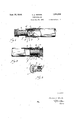
- FIG. 1 shows a hose end in which a male hose coupling is being inserted, and illustrates the construction and operation of my coupling;
- Fig. 2 shows the insertion of the coupling section in the hose end; the coupling section being female instead of male;
- Fig. 3 shows in perspective one of the thimbles constituting one of the elements of my coupling inserted and locked in place in the hose end;
- Fig. 4 shows a hose end in which a male coupling is inserted and rendered water tight by the second mode of carrying my device into practice
- Fig. 5 shows the elements of the same coupling separated from each other
- Fig. 6 shows in perspective the thimble section of my hose coupling
- Fig. 7 shows a sectional perspective of the flange ring section provided on the outer end of said thimble section
- Fig. 8 shows a possible simplification of the said construction of my hose coupling
- Fig. 9 illustrates a possible variation in the means for securing the thimble section of my coupling in the hose end against movement.
- each of the hose ends as a to be coupled is inserted the thimble element b of my coupling.
- the wall of this thimble consists of outer and inner spaced sections c, d united by. frangible connections e, and the inner section (I must be threaded.
- the extremity of the outer section 0 is provided with a flange f and the extremity of the inner section (1 is provided with radially disposed expansible prongs g initially lying within the circumference of the thimble.
- the coupling section whether male or female, consists of a nipple h adapted to be threaded into the inner thimble section d and provided with a flange z.
- the thimble b is first inserted in the hose end, with its flange f in close abutment with the hose end. Then the nipple It will be threaded into the the thimble, in which operation the prongs g of the thimble b will be spread outward and caused to become firmly engaged with the interior of the wall of the hose end as illustrated in Fig. 2.
- the nipple h of the coupling section is made of such length that after it has entered the inner section d of the thimble b and has spread the prongs g apart so as to become engaged with the hose end, as mentioned, there will still remain a portion of the nipple h. projecting outward of the flange 1 of the thimble b.
- the threading of the nipple of the coupling section into the thimble projects the latters prongs a into the wall of the hose end and thus secures said inner thimble section (1 against movement, either longitudinal or rotary.
- frangible connections e between the outer and inner sections 0, d of the thimble are adapted to permit the further movement of the outer thimble section c into the hose end, either by rupture of said frangible connections or their distortion after the inner thimble section d is held in place.
- a washer m of yielding material may be inserted between the flange f of the thimble and the hose end as shown by Fig. 2.
- the flange f of the thimble may be cupped as shown by k in Fig. 2, so that as the parts are drawn together said cupped flange portion k will restrain the spreading outward of the hose end under the pressure of the flange f of the thimble against it.
- a clamping ring as Z, see Fig. 2, or other band-like means, may be employed.
- a washer is inserted between the flange i of the coupling section it and the flange f of the thimble, since such assures the best water-tight fitting.
- This flange preferably is made narrow and engages with a flange ring r.
- a perspective of this flange ring is shown by Fig. '7.
- the thimble o In the thimble o is threaded the nipple s of the coupling section 3 provided with a flange it. Before threading the nipple of the coupling s into the thimble o, a rubber washer u. is placed The thimble is in the first instance inserted its full length into the hose-end n, so as to bring the flange ring 1' as tightly as possible against the washer u, and the latter against the rim of the hose end.
- the prongs p at the inner end of the latter are expanded outwardly, and caused to engage with the wall of the hose end, as illustrated in Fig. 4.
- the flange t of the hose coupling section s is caused to bear firmly on the washer v placed under the flange ring r; and the latter then bears firmly on the washer it which in turn bears firmly against the rim of the hose end, thereby providing the desired water-tight joint for my hose coupling.
- FIG. 8 A possible simplification of the second construction of my hose coupling is illustrated by Fig. 8.
- the washer u and flange ring 1- included in the construction shown by Figs. 4 and 5 of my drawings, may be omitted, and the washer 12 will then be brought into firm contact with the rim of the hose end over the flange q of the nipple s and form a water-tight joint therewith.
- the latter may be omitted, if preferred, in order to simplify the construction; and instead the thimble may be secured against longitudinal or rotary movement, by the customary clamp represented by w in Fig. 9; thereby compressing the hose-end n firmly on the nipple o.
- the remainder of the construction of my coupling may be as shown by Fig. 9, or as shown by Figs. 4 and 5.
- the flange q of the thimble section of my hose coupling may also possibly be omitted for simplification.
- the described modification of my hose coupling must be left to the judgment of the manufacturer; taking into consideration dependability as the main factor.
- a thimble adapted to be inserted in the hose end, said thimble comprising inner and outer spaced sections, the inner section being threaded, said sections joined by a yielding connection accommodating longitudinal movement of said outer section towards said inner section, said outer section provided with a flange, means for securing said inner section against displacement in the hose end, and a coupling section threading into said inner section having a nipple provided with a flange, whereby the threading of the coupling section into the thimble will move the outer section of the thimble inward, and therewith its flange against the hose end.
- a thimble adapted to be inserted in the hose end, said thimble comprising inner and outer spaced sections, the inner section being threaded, said sections joined by a yielding connection accommodating longitudinal movement of said outer section towards said inner section, said outer section provided with a flange, said inner section of the nipple provided with means expansible into locking engagement with the wall of a hose end, such means initially lying within the circumference of said thimble, and a coupling section threading into said inner section, having a nipple provided with a flange whereby the threading of the coupling section into the thimble will move the outer section of the thimble inward, and therewith its flange against the hose end.
- a hose coupling fixture comprising a thimble adapted to be inserted in a hose end, said thimble comprising inner and outer spaced sections, the inner section being threaded and said sections joined by a connection accommodating longitudinal movement of said outer section towards said inner section, said outer section provided with a flange, means for securing said inner thimble section against displacement in the hose end.
- a hose coupling the combination of a thimble adapted to be inserted in a hose end, the outer end of said thimble provided with a narrow flange, said thimble provided with means for securing it against longitudinal displacement in the hose end, a coupling section having a nipple threading into said thimble and provided with a flange the width of which is equal to the thickness of the wall of said hose end, a washer between the flange oi the coupling sec-
Landscapes
- Engineering & Computer Science (AREA)
- General Engineering & Computer Science (AREA)
- Mechanical Engineering (AREA)
- Quick-Acting Or Multi-Walled Pipe Joints (AREA)
Description
T. A. WEINKE HOSE COUPLING Sept. 25, 1934.
Filed July 31, 1933 2 Sheets-Sheet Sept. 25, 1934. T. A. WEINKE 1,974,635
HOSE COUPLING Filed July '31, 1953 2 Sheets-Shet 2 in l Patented Sept. 25, 1934 HOSE COUPLING Theodore A. Weinke, Portland, Oreg.
Application July 31, 1933, Serial No. 683,233
7 Claims.
My invention relates to garden hose couplings of the type which consists of metal male and female threaded sections, provided with nipples adapted to be inserted in the hose ends to be coupled, and the coupling being made by screwing said coupling sections together.
The objection to couplings of this type is the difllculty, if not the practical impossibility of so fastening the respective coupling sections in the hose ends as to prevent the pressure of the water delivered thru the hose from escaping from one of the hose ends over the nipple of the coupling section, thus not only reducing the ejected stream of water in column and velocity, but the water escaping from the hose connection is apt to be projected on the person using the hose.
The reason for such escape of water from the hose coupling is, it is not practicable to obtain a water-tight contact between the hose end and the nipple of the coupling section, no matter how firmly the hose end may be clamped on the nipple.
The object of my invention is to provide a coupling of the character mentioned, by which the escape of water at the coupling is effectively prevented.
The major principle of construction and operation of my invention consists in inserting in the hose end and securing therein against longitudinal and rotary movement, a threaded thimble to receive the nipple of a hose coupling section, and introducing between the latter and the rim of the hose end, means including a gasket or washer element to prevent escape of water between the hose end and the coupling.
Such principle may be carried into practice in two different modes, both of which are illustrated in the accompanying drawings and hereinafter fully described.
In the drawings:
Figs. 1 to 3 illustrate one construction of my hose coupling;
Figs. 4 to '7 illustrate another embodiment; thus Fig. 1 shows a hose end in which a male hose coupling is being inserted, and illustrates the construction and operation of my coupling;
Fig. 2 shows the insertion of the coupling section in the hose end; the coupling section being female instead of male;
Fig. 3 shows in perspective one of the thimbles constituting one of the elements of my coupling inserted and locked in place in the hose end;
Fig. 4 shows a hose end in which a male coupling is inserted and rendered water tight by the second mode of carrying my device into practice;
Fig. 5 shows the elements of the same coupling separated from each other;
Fig. 6 shows in perspective the thimble section of my hose coupling;
Fig. 7 shows a sectional perspective of the flange ring section provided on the outer end of said thimble section;
Fig. 8 shows a possible simplification of the said construction of my hose coupling; and
Fig. 9 illustrates a possible variation in the means for securing the thimble section of my coupling in the hose end against movement.
Describing first the construction of my invention as shown by Figs. 1 to 3, inclusive:
In each of the hose ends as a to be coupled is inserted the thimble element b of my coupling. The wall of this thimble consists of outer and inner spaced sections c, d united by. frangible connections e, and the inner section (I must be threaded. The extremity of the outer section 0 is provided with a flange f and the extremity of the inner section (1 is provided with radially disposed expansible prongs g initially lying within the circumference of the thimble. The coupling section, whether male or female, consists of a nipple h adapted to be threaded into the inner thimble section d and provided with a flange z. The thimble b is first inserted in the hose end, with its flange f in close abutment with the hose end. Then the nipple It will be threaded into the the thimble, in which operation the prongs g of the thimble b will be spread outward and caused to become firmly engaged with the interior of the wall of the hose end as illustrated in Fig. 2.
The nipple h of the coupling section is made of such length that after it has entered the inner section d of the thimble b and has spread the prongs g apart so as to become engaged with the hose end, as mentioned, there will still remain a portion of the nipple h. projecting outward of the flange 1 of the thimble b. The threading of the nipple of the coupling section into the thimble projects the latters prongs a into the wall of the hose end and thus secures said inner thimble section (1 against movement, either longitudinal or rotary. The frangible connections e between the outer and inner sections 0, d of the thimble are adapted to permit the further movement of the outer thimble section c into the hose end, either by rupture of said frangible connections or their distortion after the inner thimble section d is held in place.
Thus by completing the threading of the nipple h into the thimble b, the pressure brought to bear on the frangible connections e of the thim- 110 under the flange ring r.
ble sections 0 and d will cause such connections to break, or to yield to distortion; and thus the complete threading of the nipple h into the thimble b will cause the flange f of the thimble section to bear so firmly against the hose end a as to effect a water-tight joint with it.
In consequence, the complete threading of the nipple h. of the coupling section into the thimble b finally causes the flange ,f of the latter to bear so firmly against the hose end as to assure a water-tight joint.
In order further to assure a water-tight connection between the flange of the thimble and the ,hose end a as mentioned, a washer m of yielding material, preferably also having cementitious surfaces, may be inserted between the flange f of the thimble and the hose end as shown by Fig. 2.
In order to provide further assurance for forming said water-tight joint, the flange f of the thimble may be cupped as shown by k in Fig. 2, so that as the parts are drawn together said cupped flange portion k will restrain the spreading outward of the hose end under the pressure of the flange f of the thimble against it.
In order to restrain the outward yield of the hose wall when under the pressure of the prongs g of the inner section d of the thimble, a clamping ring, as Z, see Fig. 2, or other band-like means, may be employed.
Preferably a washer, not shown, is inserted between the flange i of the coupling section it and the flange f of the thimble, since such assures the best water-tight fitting.
In the construction of my coupling, shown by Figs. 4 to 7 inclusive, the end of the hose 1!. has inserted in it a thimble 0, provided at its inner end with expansible prongs p, and provided at its outer end with a flange q. (A perspective view of this thimble is shown by Fig. 6.)
This flange preferably is made narrow and engages with a flange ring r. A perspective of this flange ring is shown by Fig. '7.
In the thimble o is threaded the nipple s of the coupling section 3 provided with a flange it. Before threading the nipple of the coupling s into the thimble o, a rubber washer u. is placed The thimble is in the first instance inserted its full length into the hose-end n, so as to bring the flange ring 1' as tightly as possible against the washer u, and the latter against the rim of the hose end. By then screwing in the nipple s of the hose coupling section 3 into the thimble o, the prongs p at the inner end of the latter are expanded outwardly, and caused to engage with the wall of the hose end, as illustrated in Fig. 4. At the same time the flange t of the hose coupling section s is caused to bear firmly on the washer v placed under the flange ring r; and the latter then bears firmly on the washer it which in turn bears firmly against the rim of the hose end, thereby providing the desired water-tight joint for my hose coupling.
A possible simplification of the second construction of my hose coupling is illustrated by Fig. 8. The washer u and flange ring 1-, included in the construction shown by Figs. 4 and 5 of my drawings, may be omitted, and the washer 12 will then be brought into firm contact with the rim of the hose end over the flange q of the nipple s and form a water-tight joint therewith.
Instead of providing the inner end of the thimble 0 with prongs as p, the latter may be omitted, if preferred, in order to simplify the construction; and instead the thimble may be secured against longitudinal or rotary movement, by the customary clamp represented by w in Fig. 9; thereby compressing the hose-end n firmly on the nipple o. The remainder of the construction of my coupling may be as shown by Fig. 9, or as shown by Figs. 4 and 5.
The flange q of the thimble section of my hose coupling may also possibly be omitted for simplification. The described modification of my hose coupling must be left to the judgment of the manufacturer; taking into consideration dependability as the main factor.
While I have described my invention as a coupling for garden hose, this is merely one of its uses and many further uses will suggest themselves.
Without limiting myself to the precise details above described, what I claim is:
1. In a hose coupling the combination of a thimble adapted to be inserted in the hose end, said thimble comprising inner and outer spaced sections, the inner section being threaded, said sections joined by a yielding connection accommodating longitudinal movement of said outer section towards said inner section, said outer section provided with a flange, means for securing said inner section against displacement in the hose end, and a coupling section threading into said inner section having a nipple provided with a flange, whereby the threading of the coupling section into the thimble will move the outer section of the thimble inward, and therewith its flange against the hose end.
2. In a hose coupling the combination of a thimble adapted to be inserted in the hose end, said thimble comprising inner and outer spaced sections, the inner section being threaded, said sections joined by a yielding connection accommodating longitudinal movement of said outer section towards said inner section, said outer section provided with a flange, said inner section of the nipple provided with means expansible into locking engagement with the wall of a hose end, such means initially lying within the circumference of said thimble, and a coupling section threading into said inner section, having a nipple provided with a flange whereby the threading of the coupling section into the thimble will move the outer section of the thimble inward, and therewith its flange against the hose end.
3. The combination of claim 2 in which the expansible means for securing the inner section of the thimble against displacement in a hose end, consist of radially disposed prongs initially lying within the circumference of said thimble.
4. The combination of claim 2 including a collar clamped to said hose over said expansible locking means of the inner thimble section.
5. A hose coupling fixture comprising a thimble adapted to be inserted in a hose end, said thimble comprising inner and outer spaced sections, the inner section being threaded and said sections joined by a connection accommodating longitudinal movement of said outer section towards said inner section, said outer section provided with a flange, means for securing said inner thimble section against displacement in the hose end.
6. The combination of claim 5 in which said means for securing the inner thimble section against displacement in the hose end consists of radially expansible portions initially lying within the circumference of said thimble.
7. In a hose coupling the combination of a thimble adapted to be inserted in a hose end, the outer end of said thimble provided with a narrow flange, said thimble provided with means for securing it against longitudinal displacement in the hose end, a coupling section having a nipple threading into said thimble and provided with a flange the width of which is equal to the thickness of the wall of said hose end, a washer between the flange oi the coupling sec-
Priority Applications (1)
| Application Number | Priority Date | Filing Date | Title |
|---|---|---|---|
| US683233A US1974635A (en) | 1933-07-31 | 1933-07-31 | Hose coupling |
Applications Claiming Priority (1)
| Application Number | Priority Date | Filing Date | Title |
|---|---|---|---|
| US683233A US1974635A (en) | 1933-07-31 | 1933-07-31 | Hose coupling |
Publications (1)
| Publication Number | Publication Date |
|---|---|
| US1974635A true US1974635A (en) | 1934-09-25 |
Family
ID=24743120
Family Applications (1)
| Application Number | Title | Priority Date | Filing Date |
|---|---|---|---|
| US683233A Expired - Lifetime US1974635A (en) | 1933-07-31 | 1933-07-31 | Hose coupling |
Country Status (1)
| Country | Link |
|---|---|
| US (1) | US1974635A (en) |
Cited By (3)
| Publication number | Priority date | Publication date | Assignee | Title |
|---|---|---|---|---|
| US6158784A (en) * | 1998-04-07 | 2000-12-12 | Aeroquip Corporation | Connector for tubular members |
| US20140326724A1 (en) * | 2013-05-02 | 2014-11-06 | Magna Steyr Fuel Systems Gesmbh | Tank system |
| WO2018015043A1 (en) * | 2016-07-19 | 2018-01-25 | Contitech Mgw Gmbh | Support sleeve |
-
1933
- 1933-07-31 US US683233A patent/US1974635A/en not_active Expired - Lifetime
Cited By (4)
| Publication number | Priority date | Publication date | Assignee | Title |
|---|---|---|---|---|
| US6158784A (en) * | 1998-04-07 | 2000-12-12 | Aeroquip Corporation | Connector for tubular members |
| US20140326724A1 (en) * | 2013-05-02 | 2014-11-06 | Magna Steyr Fuel Systems Gesmbh | Tank system |
| US9688525B2 (en) * | 2013-05-02 | 2017-06-27 | Magna Steyr Fuel Systems Gesmbh | Tank system |
| WO2018015043A1 (en) * | 2016-07-19 | 2018-01-25 | Contitech Mgw Gmbh | Support sleeve |
Similar Documents
| Publication | Publication Date | Title |
|---|---|---|
| US5160175A (en) | Quick pipe coupling with inflatable seal and pin retainer | |
| ES2913553T3 (en) | Hoses and hose adapters | |
| US2247032A (en) | Pipe joint | |
| US2386562A (en) | Hose coupling | |
| JPS5926144Y2 (en) | Hose and fitting assembly | |
| AU598278B2 (en) | Pipe connector | |
| SE7909446L (en) | DEVICE FOR CONNECTING HOSE AND RUBBER ENDS | |
| US2907591A (en) | Hose coupling having bayonet type joining means | |
| US2245037A (en) | Coupling for flexible pipes | |
| US2127086A (en) | Hose coupling | |
| US2447947A (en) | Variable union | |
| US1974635A (en) | Hose coupling | |
| US2558695A (en) | Pipe coupling | |
| US2299434A (en) | Plumber's pipe testing device | |
| US4166479A (en) | Blind liner for service pipes | |
| US2829673A (en) | Pipe unions | |
| US3087747A (en) | Connector for resilient tubing | |
| US2449916A (en) | Coupling device | |
| US431816A (en) | lomasney | |
| US2449659A (en) | Quick coupling for hose | |
| US2742305A (en) | Quick detachable, fluid pressure actuated coupling | |
| US2472569A (en) | Means for securing a pipe fitting to a plate, wall, or the like | |
| US2911237A (en) | Coupling for resilient tubular members | |
| US2799520A (en) | Screw-fed type hose coupling with wire anchor coil | |
| US3695648A (en) | Coupling |