US1974591A - Spring connection - Google Patents
Spring connection Download PDFInfo
- Publication number
- US1974591A US1974591A US628056A US62805632A US1974591A US 1974591 A US1974591 A US 1974591A US 628056 A US628056 A US 628056A US 62805632 A US62805632 A US 62805632A US 1974591 A US1974591 A US 1974591A
- Authority
- US
- United States
- Prior art keywords
- frame
- bearing
- spring
- plates
- bolts
- Prior art date
- Legal status (The legal status is an assumption and is not a legal conclusion. Google has not performed a legal analysis and makes no representation as to the accuracy of the status listed.)
- Expired - Lifetime
Links
Images

Classifications
-
- F—MECHANICAL ENGINEERING; LIGHTING; HEATING; WEAPONS; BLASTING
- F02—COMBUSTION ENGINES; HOT-GAS OR COMBUSTION-PRODUCT ENGINE PLANTS
- F02B—INTERNAL-COMBUSTION PISTON ENGINES; COMBUSTION ENGINES IN GENERAL
- F02B75/00—Other engines
- F02B75/28—Engines with two or more pistons reciprocating within same cylinder or within essentially coaxial cylinders
-
- B—PERFORMING OPERATIONS; TRANSPORTING
- B27—WORKING OR PRESERVING WOOD OR SIMILAR MATERIAL; NAILING OR STAPLING MACHINES IN GENERAL
- B27L—REMOVING BARK OR VESTIGES OF BRANCHES; SPLITTING WOOD; MANUFACTURE OF VENEER, WOODEN STICKS, WOOD SHAVINGS, WOOD FIBRES OR WOOD POWDER
- B27L5/00—Manufacture of veneer ; Preparatory processing therefor
- B27L5/08—Severing sheets or segments from veneer strips; Shearing devices therefor; Making veneer blanks, e.g. trimming to size
-
- B—PERFORMING OPERATIONS; TRANSPORTING
- B60—VEHICLES IN GENERAL
- B60G—VEHICLE SUSPENSION ARRANGEMENTS
- B60G11/00—Resilient suspensions characterised by arrangement, location or kind of springs
- B60G11/02—Resilient suspensions characterised by arrangement, location or kind of springs having leaf springs only
- B60G11/10—Resilient suspensions characterised by arrangement, location or kind of springs having leaf springs only characterised by means specially adapted for attaching the spring to axle or sprung part of the vehicle
- B60G11/12—Links, pins, or bushes
Definitions
- My invention relates to a spring connection and more particularly to a hinge-lend ⁇ connection.
- ⁇ It is the general object ofthe invention to provide a vspring connection whichisrsimple in l 5 construction, sturdy, of few parts, simply asseml Other objects and features of inventionr will be hereinafter pointed out or fwill become apparent ⁇ upon a readingof the specification.
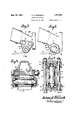
- w .-In the drawings which show, vfor illustrative purposes only, preferred formsV of the invention- 'l5 Fig, 1 is a fragmentary side View of a connected frame and spring and illustrating features ⁇ of the invention; I l Y l u .g Fig. 2 is a sectional view takensubstantially in the plane of the line 2-2 of Fig.
- Fig. 3 is a View similar to Fig; 1but illustrating a modified form of connection;
- ,-y g1 Fig. 4 is a sectional view taken substantially in the plane of the line 4;-4 of Fig.,3;
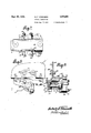
- g i Fig. 5 is a view similar to Fig. l, but illustrating a modified form of connection; l
- l f Fig. 6 ⁇ is a sectional View taken substantially in the plane ⁇ of the line 6-6 ⁇ of Fig. 5; J l Fig. 'lisa top plan view Vof a spring connection and bracket illustrating a modified form of spring connection; p 1, n y Fig. 8 isa side viewfin elevation of -thparts shown in Fig. 7 assembled with a spring; Y Fig. 9is an end view in partial section ofparts shown in Figs. '7 and 8.
- 5 indicates a ⁇ frame part, while 6 indicates a spring to be hingedly ⁇ connected thereto.
- One, of the 4,members ⁇ such as ⁇ thefrarne 5 carries abearing raceway meansV in the form of plates 7-7 each .of
- the plates '7 are secured to the frame at opposite sides thereof pref- -l denitely space the same apart and so as to take end. thrustloads between'. the frame andV springt'.
- the raceways areA preferably designed so that the anti-friction bearing members 9 take only radial loads between the frame and spring.
- the length of the pin 11 is preferably such that the side @n plates or links 7,-7 ⁇ may be sprung slightly when the nuts on the throughbolts 10--10 are drawn up to rigidly secure the plate 7 7 to the frame.
- the anti-friction bearing members 9-9 may beheld ⁇ infplace in the side plates 7 when the latter are disassembled from the frame by means of Va sheet metal plate member 13 which may be frictionally held in the cupped ⁇ portion of each side plate, and the sheet metal plate 13 is preferably substantially coextensive with y the side plate 7 so as to be interposed between the latter, and theframe and be thus rigidly held in placegwhen thehinge connection is assembled.
- Lubricant may ⁇ be retained onand foreign mat- ⁇ ter excluded from the anti-friction bearing rsur-V faces partly by means of the plate 13 and further by agfeltor other dust ring 14.
- each of the bolts Y carriesv more orV less the same loading.
- ⁇ a cantilever type of plate whichyis se,- 95, curedrat one part tov the frame andhasa substantially overhanging part constituting the raceways.
- the parts may therefore in many cases be made lighter and, consequently, cheaper than the so called cantilever types.
- each side plate 16 is preferably provided with a marginal flange 18 surrounding the same so as to provide adequate stiiness and strength to the plates, and which flanges may overlap a projecting boss 19 at each side of the frame.
- the frame denitely spaces the side plates apart, and the pin or other bearing means l1 carried by the spring may serve to slightly stress the side plates by spacing the same apart whereby end thrusts are taken by 'the pin l1 and the side plates and radial loads are taken by the anti-friction bearing members.
- the frame part 5 is provided with spaced apart bosses 20-20 having alined bores 21-21.
- a bearing raceway member such as the bearing cup 22 which carries antifrictionbearing members such as balls 23.
- the balls may be held in place in-the cups by means o1 a sheet metal cup-like retainer 24.
- the spring 6 carries complementary raceway means preferably in the formofV raceways 25 formed at the ends of a pin 26 carried by the spring eye. Balls 23 are interposed between the complementary raceways of the cups 22 and the raceways 25 on the pin. Means such as a retaining plate 27 is secured over each of the cups 22, and, in the form shown, the plate is a strip of metal which may be slightlyresilient so as to provide a slight give in the nished hinge connection.
- the plates 2'7-27 are secured to the frame 5 or the bosses 20-20 thereon preferably by means of through bolts 28-28 so that when the nuts on said through bolts are screwed up tight, the retaining plates 27-27 will be rigidly secured to the frame, and the through bolts furthermore resist any spreading tendency between thev spaced apart bosses of the frame 5.
- The' length of the pin 26 is preferably such as to engage the bearing cups 22 substantially centrally when the retaining plates 27-27 are in assembled condition with the frame.
- the frame itself or rather the bosses thereon, sustain the bearing cups 22-22 in a radial direction, and the plates 27, together with the through bolts sustain the bearing cups against axial displacement inthe bores, which through bolts also brace the spaced apart bosses and provide a sturdy construction.
- FIG. 7 indicates an intermediate portion of an automobile frame comprising a vertical web 30 and a horizontal ange 3l.
- the frame part or bracket in this case -comprises an angular form of bracket having a horizontal portion 32 to be secured to the horizontal flange 23 as by meansrof bolts 33.
- the bracket vis further provided with a vertically extending ange 34 which is secured to the vertical web 30 of the frame by means of bolts 35.
- the bracket has spaced apart bosses 36-36 which are provided with alined bores such as 37 for the reception of bearing raceways such as cups 38, the same or similar to those described in connection with Figs. 5 and 6.
- the 4cups 38 are held in the bores 37 by means of cover plates 39-39 covering the bores and secured to the bosses by means of through bolts l0-40, which not only retain the bearing cups in the bores, but serve to brace the spaced apart bosses relatively to each other and add to the sturdiness of the construction.
- the bearing means such as the pin 41 carried by the spring eye interposed between the spaced apart bosses may be provided with a reduced end portion 42 to engage each of the bearing cups centrally and preferably in a depression 43 therein whereby end thrusts are taken between the bearing cups and bearing pin 41 as heretofore described in connection with the other forms of the invention.
- the through bolts Li0-fi0 are preferably located on opposite sides of a veitical diametrical plane through the bearings so that the stresses are more or less equally divided between the through bolts and, in addition, the bolts 35435 and 33-433, securing the bracket to the frame 5', are preferably arranged on opposite sides of the same vertical plane for the same reason.
- a frame In a spring connection, a frame, a spring, bearing pin means fixedly carried by said spring and projecting from opposite sides thereof, a pair of plates von said frame at opposite sides thereof, each of said plates having an outwardly bowed portion forming a bearing cup onthe inner side of said plate and extending over-and engaging the ends of said bearing pin meansanti-friction bearing members seated in said cups and engag ing the projecting portions of saidi'pin means, means for retaining said anti-friction bearing members in said cups, and means positioned at opposite sides of a diametri'cal plane through said cups and bearing pinv means for rigidly securing said plates to saidframe, said last mentioned means constituting the sole support of said plates and serving to transmit loads between said frame and spring.
Landscapes
- Engineering & Computer Science (AREA)
- Mechanical Engineering (AREA)
- Life Sciences & Earth Sciences (AREA)
- Manufacturing & Machinery (AREA)
- Wood Science & Technology (AREA)
- Forests & Forestry (AREA)
- Chemical & Material Sciences (AREA)
- Combustion & Propulsion (AREA)
- General Engineering & Computer Science (AREA)
- Closing And Opening Devices For Wings, And Checks For Wings (AREA)
Description
. Sept. 25, 1934. R. F. sTEENEcK I SPRING CONNEQTLQN Filed Aug. 9l 1932 3 Sheets-Sheet 1 INVEN-r-:DRr
@0M ff/banal? ATTORNEYS,
SQP- 25, 1934 R; F. s'rEENl-:CK 1,974,591
SPRING CONNECTION Filed Aug. 9. 1932 3 Sheets-Sheet 2 d? BY,gVENTOR a Sept.- 25, A1934.
Filed Aug. 9, 1932 3 Sheets-Sheet 3 AIl :lllllmu "INVENQTOR d: 5
ATro NEYS.
Patented Sept. 25, 1934 Muga-.M
f? UNITEDSTATES 4'.TENT OFFICE' `1,9%',7591 t SPRING CONNECTION t v Robertv F. -Steeneck,V Detroit, Mich., assignor to' TheFatnir Bearing: Company, New Britain.
Conn., a corporation ofConnecticut Appleman. August 9,"` 19132, serial No. 628,05@ 1 claim (ci. Azeig-54;).
My invention relates to a spring connection and more particularly to a hinge-lend` connection. `It is the general object ofthe invention to provide a vspring connection whichisrsimple in l 5 construction, sturdy, of few parts, simply asseml Other objects and features of inventionr will be hereinafter pointed out or fwill become apparent` upon a readingof the specification. w .-In the drawings which show, vfor illustrative purposes only, preferred formsV of the invention- 'l5 Fig, 1 is a fragmentary side View of a connected frame and spring and illustrating features `of the invention; I l Y l u .g Fig. 2 is a sectional view takensubstantially in the plane of the line 2-2 of Fig. 1; 2o Fig. 3 is a View similar to Fig; 1but illustrating a modified form of connection; ,-y g1 Fig. 4 is a sectional view taken substantially in the plane of the line 4;-4 of Fig.,3; g i Fig. 5 is a view similar to Fig. l, but illustrating a modified form of connection; l
l f Fig. 6` is a sectional View taken substantially in the plane `of the line 6-6 `of Fig. 5; J l Fig. 'lisa top plan view Vof a spring connection and bracket illustrating a modified form of spring connection; p 1, n y Fig. 8 isa side viewfin elevation of -thparts shown in Fig. 7 assembled with a spring; Y Fig. 9is an end view in partial section ofparts shown in Figs. '7 and 8.
375 i In the form shown in Figs. 14 and `2, 5 indicates a `frame part, while 6 indicates a spring to be hingedly `connected thereto. One, of the 4,members `such as `thefrarne 5 carries abearing raceway meansV in the form of plates 7-7 each .of
`4.o generally symmetrical form and provided substantially centrally with a raceway 8 formed by cupping the plate '7, as will be understood. Antifriction bearing `members such as balls 9 may be carried by the raceway 8. The plates '7 are secured to the frame at opposite sides thereof pref- -l denitely space the same apart and so as to take end. thrustloads between'. the frame andV springt'. The raceways areA preferably designed so that the anti-friction bearing members 9 take only radial loads between the frame and spring. The length of the pin 11 is preferably such that the side @n plates or links 7,-7`may be sprung slightly when the nuts on the throughbolts 10--10 are drawn up to rigidly secure the plate 7 7 to the frame. Thus,l all4 looseness and liability to rattle are eliminated. 65, The anti-friction bearing members 9-9 may beheld` infplace in the side plates 7 when the latter are disassembled from the frame by means of Va sheet metal plate member 13 which may be frictionally held in the cupped `portion of each side plate, and the sheet metal plate 13 is preferably substantially coextensive with y the side plate 7 so as to be interposed between the latter, and theframe and be thus rigidly held in placegwhen thehinge connection is assembled. Lubricant may `be retained onand foreign mat-` ter excluded from the anti-friction bearing rsur-V faces partly by means of the plate 13 and further by agfeltor other dust ring 14. It may t in the cupped plate 13 and it may be backed up `by @Q means ofV a sheet metal Washer Y15 carried by eachof the projecting ends of the pin 1,1. Akvery simple, cheap and effective hinge con-` nectionv hasl thus been provided. Assembly and disassembly arel a very simple operation, ,and 85, there are no partslikely to getout of order. It willxfurtherr -be` notedA that the through .bolts 10H10 are on opposite sides of a vertical diametrioalv plane .through the bearing raceways. Since `most of the forces between the frame-.and 90, springl are ina vertical plane through the axis of the-raceways, Yit will be seen that each of the bolts Ycarriesv more orV less the same loading. Such Wouldnot. be the case with what may be termed `a cantilever type of plate, whichyis se,- 95, curedrat one part tov the frame andhasa substantially overhanging part constituting the raceways. The parts may therefore in many cases be made lighter and, consequently, cheaper than the so called cantilever types.
In the form shown in Figs. 3 and l4, the construction and operation are quite similar to that of the forms shown in Figs. 1 and 2. In Figs.
3 and 4, the side plates 16 are secured Vto the frame 5 by means of through bolts 10e-10 which 105 are spaced on opposite sides of a vertical diametrical plane through the cupped raceways 17--1'7 thereon. The raceway portions of the side plates 16--16 overhang slightly but the forces are still more or less equally distributed between 1i@ the two through bolts 10-10. In the Figs. 3-4 form, each side plate 16 is preferably provided with a marginal flange 18 surrounding the same so as to provide adequate stiiness and strength to the plates, and which flanges may overlap a projecting boss 19 at each side of the frame. As with the first form of the invention, the frame denitely spaces the side plates apart, and the pin or other bearing means l1 carried by the spring may serve to slightly stress the side plates by spacing the same apart whereby end thrusts are taken by 'the pin l1 and the side plates and radial loads are taken by the anti-friction bearing members.
In that form of the invention shown in Figs. 5 and 6, the frame part 5 is provided with spaced apart bosses 20-20 having alined bores 21-21. In each bore there is a bearing raceway member such as the bearing cup 22 which carries antifrictionbearing members such as balls 23. The balls may be held in place in-the cups by means o1 a sheet metal cup-like retainer 24.
The spring 6 carries complementary raceway means preferably in the formofV raceways 25 formed at the ends of a pin 26 carried by the spring eye. Balls 23 are interposed between the complementary raceways of the cups 22 and the raceways 25 on the pin. Means such as a retaining plate 27 is secured over each of the cups 22, and, in the form shown, the plate is a strip of metal which may be slightlyresilient so as to provide a slight give in the nished hinge connection. Y Y
The plates 2'7-27 are secured to the frame 5 or the bosses 20-20 thereon preferably by means of through bolts 28-28 so that when the nuts on said through bolts are screwed up tight, the retaining plates 27-27 will be rigidly secured to the frame, and the through bolts furthermore resist any spreading tendency between thev spaced apart bosses of the frame 5. The' length of the pin 26 is preferably such as to engage the bearing cups 22 substantially centrally when the retaining plates 27-27 are in assembled condition with the frame. Thus, the frame itself, or rather the bosses thereon, sustain the bearing cups 22-22 in a radial direction, and the plates 27, together with the through bolts sustain the bearing cups against axial displacement inthe bores, which through bolts also brace the spaced apart bosses and provide a sturdy construction.
In the form shown in Figs. 7, 8 and 9, 5 indicates an intermediate portion of an automobile frame comprising a vertical web 30 and a horizontal ange 3l. The frame part or bracket in this case -comprises an angular form of bracket having a horizontal portion 32 to be secured to the horizontal flange 23 as by meansrof bolts 33. The bracket vis further provided with a vertically extending ange 34 which is secured to the vertical web 30 of the frame by means of bolts 35.
The bracket has spaced apart bosses 36-36 which are provided with alined bores such as 37 for the reception of bearing raceways such as cups 38, the same or similar to those described in connection with Figs. 5 and 6. The 4cups 38 are held in the bores 37 by means of cover plates 39-39 covering the bores and secured to the bosses by means of through bolts l0-40, which not only retain the bearing cups in the bores, but serve to brace the spaced apart bosses relatively to each other and add to the sturdiness of the construction.
' The bearing means such as the pin 41 carried by the spring eye interposed between the spaced apart bosses may be provided with a reduced end portion 42 to engage each of the bearing cups centrally and preferably in a depression 43 therein whereby end thrusts are taken between the bearing cups and bearing pin 41 as heretofore described in connection with the other forms of the invention.
The through bolts Li0-fi0, as in the other forms, are preferably located on opposite sides of a veitical diametrical plane through the bearings so that the stresses are more or less equally divided between the through bolts and, in addition, the bolts 35435 and 33-433, securing the bracket to the frame 5', are preferably arranged on opposite sides of the same vertical plane for the same reason.
It will thus be seen that I have provided a spring connection, which is very sturdy and simple in construction and assembly, and not likely to get out of order. f
While the invention has been described in considerable detail and various forms illustrated, it is to be understood that Various changes, modications, additions, and omissions may be made wit-hin the scope of the invention as dened in the appended claim.
I claim:
In a spring connection, a frame, a spring, bearing pin means fixedly carried by said spring and projecting from opposite sides thereof, a pair of plates von said frame at opposite sides thereof, each of said plates having an outwardly bowed portion forming a bearing cup onthe inner side of said plate and extending over-and engaging the ends of said bearing pin meansanti-friction bearing members seated in said cups and engag ing the projecting portions of saidi'pin means, means for retaining said anti-friction bearing members in said cups, and means positioned at opposite sides of a diametri'cal plane through said cups and bearing pinv means for rigidly securing said plates to saidframe, said last mentioned means constituting the sole support of said plates and serving to transmit loads between said frame and spring. 'l f ROBERT F. STEENECK.
ris
Priority Applications (1)
| Application Number | Priority Date | Filing Date | Title |
|---|---|---|---|
| US628056A US1974591A (en) | 1932-08-09 | 1932-08-09 | Spring connection |
Applications Claiming Priority (1)
| Application Number | Priority Date | Filing Date | Title |
|---|---|---|---|
| US628056A US1974591A (en) | 1932-08-09 | 1932-08-09 | Spring connection |
Publications (1)
| Publication Number | Publication Date |
|---|---|
| US1974591A true US1974591A (en) | 1934-09-25 |
Family
ID=96657994
Family Applications (1)
| Application Number | Title | Priority Date | Filing Date |
|---|---|---|---|
| US628056A Expired - Lifetime US1974591A (en) | 1932-08-09 | 1932-08-09 | Spring connection |
Country Status (1)
| Country | Link |
|---|---|
| US (1) | US1974591A (en) |
-
1932
- 1932-08-09 US US628056A patent/US1974591A/en not_active Expired - Lifetime
Similar Documents
| Publication | Publication Date | Title |
|---|---|---|
| US2195795A (en) | Roller bearing | |
| US1776647A (en) | Antifriction bearing | |
| US1974591A (en) | Spring connection | |
| US2124034A (en) | Load carrying joint | |
| US1946051A (en) | Automotive axle | |
| US2796304A (en) | Pillow block | |
| US1955226A (en) | Ball and socket piston structure | |
| US1914204A (en) | Swivel bearing | |
| BR112018074446B1 (en) | VEHICLE BACKREST BEARING | |
| US2126389A (en) | Ball joint | |
| US1073530A (en) | Ball-bearing. | |
| US2037326A (en) | Leveling washer and thrust bearing cage | |
| US3384396A (en) | Ball and socket joint assembly | |
| US2125493A (en) | Lifting jack | |
| US1359506A (en) | Ball-bearing | |
| US1785654A (en) | Antifriction spring connection | |
| US1757700A (en) | Spring-end connection | |
| US1164674A (en) | Crank-shaft mounting for internal-combustion engines. | |
| US1640356A (en) | Bearing mechanism | |
| US1888801A (en) | Caster | |
| US1775803A (en) | Adjustable ball bearing | |
| US1867081A (en) | Grinding pan | |
| US1733910A (en) | Antifriction bearing | |
| US1974590A (en) | Spring connection | |
| US1635669A (en) | Vehicle antifriction spring bearing |