US1971663A - Knitting machine - Google Patents
Knitting machine Download PDFInfo
- Publication number
- US1971663A US1971663A US662974A US66297433A US1971663A US 1971663 A US1971663 A US 1971663A US 662974 A US662974 A US 662974A US 66297433 A US66297433 A US 66297433A US 1971663 A US1971663 A US 1971663A
- Authority
- US
- United States
- Prior art keywords
- latch ring
- bracket
- wrap
- machine
- needles
- Prior art date
- Legal status (The legal status is an assumption and is not a legal conclusion. Google has not performed a legal analysis and makes no representation as to the accuracy of the status listed.)
- Expired - Lifetime
Links
- 238000009940 knitting Methods 0.000 title description 10
- 230000015572 biosynthetic process Effects 0.000 description 3
- 238000010276 construction Methods 0.000 description 1
Images
Classifications
-
- D—TEXTILES; PAPER
- D04—BRAIDING; LACE-MAKING; KNITTING; TRIMMINGS; NON-WOVEN FABRICS
- D04B—KNITTING
- D04B9/00—Circular knitting machines with independently-movable needles
- D04B9/26—Circular knitting machines with independently-movable needles for producing patterned fabrics
-
- D—TEXTILES; PAPER
- D04—BRAIDING; LACE-MAKING; KNITTING; TRIMMINGS; NON-WOVEN FABRICS
- D04B—KNITTING
- D04B9/00—Circular knitting machines with independently-movable needles
- D04B9/26—Circular knitting machines with independently-movable needles for producing patterned fabrics
- D04B9/28—Circular knitting machines with independently-movable needles for producing patterned fabrics with colour patterns
Definitions
- The'object of the invention forming the-subject matter of the present case is the provision of a machine which may be used either for the production of wrapped designs or the production 110 of plain knitting, the latter being accomplished without any interference with the wrapping instrumentalities.
- the wrapping mechanism is carried by a head which may be moved upwardly all away from the needle cylinder either with the latch ring orindependently of the latch ring.
- the wrap finger 120i mechanism and the latch ring may be raised as a unit.
- the wrap finger 120i mechanism and the latch ring may be raised as a unit.
- the wrapping mechanism may be raisedupwardly while the latch ring remains down in its operative posi- "J tions, it being thus possible to watch the operation without interference by the wrapping elements. Access to the needle cylinder is gained in this case by raising the latch ring only.
- Fig. l is a right side elevation of the machine partly in section and with various parts which are not concerned with the present invention removed for clearness;
- Fig. 2 is a front elevation of the upper part of the machine certain portions thereof being removed;
- Fig. 3 is a horizontal sectional View illustrating the mounting of the latch ring and wrap finger supporting mechanism.
- the machine which is of the rotary needle type comprises a cylinder 2 mounted for rotation about a vertical axis and provided with needle receiving slots in the usual manner carrying needles.
- a platform 24 is supported from the lower portion of the frame by suitable posts.
- a bracket 26 supported by the platform 24 carries a shaft 28 upon which the latch ring supporting bracket 30 is pivoted, this bracket carrying latch ring 32.
- the supporting bracket has pivoted to its forward portion a hook 34 engageable with a pin 36 carried by an upstanding bracket 38 to maintain the latch ring in its lowered position.
- Manipulation of the hook 34 will release the hook from the pin 36 whereby the latch ring may be raised in the usual manner, a suitable spring being provided tocounterbalance its weight and tend to hold it open.
- the usual cam ring 40 com taining the cams for controlling the sinkers is provided, the cam ring having the usual freedom for oscillating movements limited by engagement of stops with the post 38.
- a bracket 42 pivoted on the shaft 28 is provided at its forward end with a downwardly extending portion 44 provided with openings through which project headed screws 46 designed to thread into the latch ring supporting bracket 30.
- a spring 47c0unter balances the weight of the bracket 42 (and the parts which it carries) so thatthis bracket will tend to remain in the po sition illustrated in Fig. 1 except when held down by the screws 46.
- the latch ring'and the bracket 42 may be raised as a unit byifreeing the hook 34 from the pin 36.
- bracket raised and the latch ring down in its operative position plain knitting may be produced whereas when the bracket 42 and the parts which it carries are also down in their operative position Wrapping of needles will take place with the formation of designs.
- the shaft 48 which carries a gear adapted to drive through an intermediate idler, the usual ring gear carried by the needle cylinder, projects upwardly and carries at its upper end a gear 52 meshing with a pinion 54, the shaft of which has a universal connection with one element 56 of a split shaft to which element the other element 58 is splined by the use of a key and slot connection.
- the upper element 58 has a universal connection with the shaft carrying a gear 60 and journalled in the bracket 42.
- the gear 60 meshes with the gear 62 which is attached to the wrap finger supporting assembly indicated generally at 64.
- the assembly 64 includes a plate 66 provided with supporting pins 68 upon which bobbins 70 may be mounted. Above these bobbins 70 there is a plate which forms a sheet for the support of tubes 72, the plate having openings therein through which the tubes extend. Yarns pass upwardly from the bobbins 70 through the tubes and thence downwardly through the member 64 to the wrap fingers.
- the wrap fingers are carried by a head forming the lower portion of the assembly and consisting of a preferably single member providing cylinders 82 and 83 having aligned vertical slots therein there being between these cylinders a groove having a semi-circular radial cross section to receive semi-circular projections of the wrap fingers and thereby provide a pivot for the same.
- the wrap fingers are held within the slots by means of a spring band.
- the wrap fingers are provided at their upper ends with butts occupying in the present machine either of two positions, the butts in the upper position being acted upon by cam 92 while those in the lower position are acted upon by cam 94, these cams being pivoted upon a vertical pin and being urged away from the butts of the wrap fingers by springs, the limiting positions being determined by a suitable stop.
- the action of the cams 92 and 9 1 is controlled by cam levers 102 and 104 pivoted to an upright post 107 and adapted to be acted upon by vertical levers 108 and 110 respectively.
- levers 108 and-110 are pivoted to the post 107 and are acted upon at their lower ends by levers 114 and 116 the former of which is carried by a vertically extending tube journalled in the frame of the machine While the latter is carried by a shaft journalled within the tube.
- the action of the levers 114 and 116 is controlled by cams on the main cam drum of the machine.
- the actuation of the wrap fingers forms no part of the invention claimed in this application and will be made clear by reference to the parent application mentioned above.
- the bracket 42 is steadied in its active position by engagement of a tapered opening in an extension 130 thereof upon a tapered pin 128 projecting fronrthe upper end of the post 107.
- a leaf spring 132 carried by the projection 130 is provided with, an opening arranged to engage over a pin 134 carried by the post 107 thus forming a releasable latch to hold the bracket in its lowered position prior to the engagement of the screws 46.
- the wrap finger supporting head is lifted while the latch ring remains in its lowered position.
- the supporting head may be raised for examination of what is taking place within the needle circle without the wrap fingers getting out of step with the needles, the angular relationship between the wrap fingers and needles being preserved by the uninterrupted drive through the two-part shaft 5658.
- a circular knitting machine including a circular series of needles and mechanism cooperating with the needles for the formation of stitches; said mechanism including means for feeding a main yarn to the needles, a latch ring, at least one wrap finger, and a supporting, head for the wrap finger, said supporting head being pivotally movable from an operative to an inoperative position independently of the latch ring or as a unit with the latch ring, the supporting head and latch ring being pivoted on a common axis, and means for fixedly securing the head and latch ring together.
- a circular knitting machine including a circular series of needles and mechanism cooperating with the needles for the formation of stitches; said mechanism including means for feeding a main yarn to the needles, a latch ring, at least one wrap finger, and a supporting head for the wrap finger, said supporting head being pivotally movable from an operative to an inoperative position independently of the latch ring or as a unit with the latch ring, there being a pivotal connection between the supporting head and latch ring, and means for fixedly securing the head and latch ring together.
Landscapes
- Engineering & Computer Science (AREA)
- Textile Engineering (AREA)
- Knitting Machines (AREA)
Description
s. R. SHELMIRE 1,971,663
KNITTING MACHINE Aug 28, 1934.
Original Filed July 18, 1-932 2 Sheets-Sheet l a 60 68 .9 e I N 7 82 N 83 lg; c /04 In n; 52
//VV'/V70 W/TA ESS: Z N Q71 6 6 mare Aug. 28, 1934. s R SHELMIRE 1,971,663
KNITTING MACHINE Original Filed July 18, 1932 2 Sheets-Sheet 2 IV/T/VESS."
Patented Aug. 28, 1934 UNITED STATES PATENT OFFICE unseat, l V
KNITTING MACHINE scanley R. .S helmir e, Wilmington, DeL, assisnor i to Standard-Trump Bros Machin'e Company, Wilmington, Del acorporation of Delaware Original application July 18, 1932, Serial No.
623,057-. Divided and this 27, 1933, Serial No. 662,974 r application March 2 Claims; (Cl. sag-135) This invention relates to a knitting machine and, specifically, a machine in which patterns are produced by wrapping." The present application is a division of my application, Serial No.
.1 35 623,057; filed July 18, 1932. l l
The'object of the invention forming the-subject matter of the present caseis the provision of a machine which may be used either for the production of wrapped designs or the production 110 of plain knitting, the latter being accomplished without any interference with the wrapping instrumentalities. Specifically, so far as this object is concerned the wrapping mechanism is carried by a head which may be moved upwardly all away from the needle cylinder either with the latch ring orindependently of the latch ring.
When it is desired to gain access to the top of the needle cylinder during the knitting ofvwork containing wrapped designs the wrap finger 120i mechanism and the latch ring may be raised as a unit. On the other hand, during adjustment, for
example, of the yarn fingers, the wrapping mechanism may be raisedupwardly while the latch ring remains down in its operative posi- "J tions, it being thus possible to watch the operation without interference by the wrapping elements. Access to the needle cylinder is gained in this case by raising the latch ring only.
Details of the invention will be apparent from the following description read in conjunction with the accompanying drawings in which:
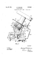
Fig. l is a right side elevation of the machine partly in section and with various parts which are not concerned with the present invention removed for clearness;
Fig. 2 is a front elevation of the upper part of the machine certain portions thereof being removed; and
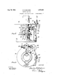
Fig. 3 is a horizontal sectional View illustrating the mounting of the latch ring and wrap finger supporting mechanism.
The machine which is of the rotary needle type comprises a cylinder 2 mounted for rotation about a vertical axis and provided with needle receiving slots in the usual manner carrying needles.
A platform 24 is supported from the lower portion of the frame by suitable posts. A bracket 26 supported by the platform 24 carries a shaft 28 upon which the latch ring supporting bracket 30 is pivoted, this bracket carrying latch ring 32. The supporting bracket has pivoted to its forward portion a hook 34 engageable with a pin 36 carried by an upstanding bracket 38 to maintain the latch ring in its lowered position.
Manipulation of the hook 34 will release the hook from the pin 36 whereby the latch ring may be raised in the usual manner, a suitable spring being provided tocounterbalance its weight and tend to hold it open. The usual cam ring 40 com taining the cams for controlling the sinkers is provided, the cam ring having the usual freedom for oscillating movements limited by engagement of stops with the post 38.
A bracket 42 pivoted on the shaft 28 is provided at its forward end with a downwardly extending portion 44 provided with openings through which project headed screws 46 designed to thread into the latch ring supporting bracket 30. A spring 47c0unterbalances the weight of the bracket 42 (and the parts which it carries) so thatthis bracket will tend to remain in the po sition illustrated in Fig. 1 except when held down by the screws 46. When secured by these screws to the latch ring support, however, the latch ring'and the bracket 42 may be raised as a unit byifreeing the hook 34 from the pin 36. As .will be hereafter pointedout, with the bracket raised and the latch ring down in its operative position plain knitting may be produced whereas when the bracket 42 and the parts which it carries are also down in their operative position Wrapping of needles will take place with the formation of designs.
The shaft 48, which carries a gear adapted to drive through an intermediate idler, the usual ring gear carried by the needle cylinder, projects upwardly and carries at its upper end a gear 52 meshing with a pinion 54, the shaft of which has a universal connection with one element 56 of a split shaft to which element the other element 58 is splined by the use of a key and slot connection. The upper element 58 has a universal connection with the shaft carrying a gear 60 and journalled in the bracket 42. The gear 60 meshes with the gear 62 which is attached to the wrap finger supporting assembly indicated generally at 64.
The assembly 64 includes a plate 66 provided with supporting pins 68 upon which bobbins 70 may be mounted. Above these bobbins 70 there is a plate which forms a sheet for the support of tubes 72, the plate having openings therein through which the tubes extend. Yarns pass upwardly from the bobbins 70 through the tubes and thence downwardly through the member 64 to the wrap fingers. The wrap fingers are carried by a head forming the lower portion of the assembly and consisting of a preferably single member providing cylinders 82 and 83 having aligned vertical slots therein there being between these cylinders a groove having a semi-circular radial cross section to receive semi-circular projections of the wrap fingers and thereby provide a pivot for the same. The wrap fingers are held within the slots by means of a spring band.
The wrap fingers are provided at their upper ends with butts occupying in the present machine either of two positions, the butts in the upper position being acted upon by cam 92 while those in the lower position are acted upon by cam 94, these cams being pivoted upon a vertical pin and being urged away from the butts of the wrap fingers by springs, the limiting positions being determined by a suitable stop. The action of the cams 92 and 9 1 is controlled by cam levers 102 and 104 pivoted to an upright post 107 and adapted to be acted upon by vertical levers 108 and 110 respectively. The levers 108 and-110 are pivoted to the post 107 and are acted upon at their lower ends by levers 114 and 116 the former of which is carried by a vertically extending tube journalled in the frame of the machine While the latter is carried by a shaft journalled within the tube. The action of the levers 114 and 116 is controlled by cams on the main cam drum of the machine. The actuation of the wrap fingers forms no part of the invention claimed in this application and will be made clear by reference to the parent application mentioned above.
The bracket 42 is steadied in its active position by engagement of a tapered opening in an extension 130 thereof upon a tapered pin 128 projecting fronrthe upper end of the post 107. A leaf spring 132 carried by the projection 130 is provided with, an opening arranged to engage over a pin 134 carried by the post 107 thus forming a releasable latch to hold the bracket in its lowered position prior to the engagement of the screws 46.
As will be obvious, when no wrap yarns are used in the machine the wrap finger supporting head is lifted while the latch ring remains in its lowered position. On the other hand, if during testing, even though the wrap fingers carry yarns and are to be used, the supporting head may be raised for examination of what is taking place within the needle circle without the wrap fingers getting out of step with the needles, the angular relationship between the wrap fingers and needles being preserved by the uninterrupted drive through the two-part shaft 5658.
It will be clear that variations may be made in the details of construction without departing from the spirit of they invention as defined in the following claims.
What I claim and desire to protect by Letters Patent is:
1. A circular knitting machine including a circular series of needles and mechanism cooperating with the needles for the formation of stitches; said mechanism including means for feeding a main yarn to the needles, a latch ring, at least one wrap finger, and a supporting, head for the wrap finger, said supporting head being pivotally movable from an operative to an inoperative position independently of the latch ring or as a unit with the latch ring, the supporting head and latch ring being pivoted on a common axis, and means for fixedly securing the head and latch ring together.
2. A circular knitting machine including a circular series of needles and mechanism cooperating with the needles for the formation of stitches; said mechanism including means for feeding a main yarn to the needles, a latch ring, at least one wrap finger, and a supporting head for the wrap finger, said supporting head being pivotally movable from an operative to an inoperative position independently of the latch ring or as a unit with the latch ring, there being a pivotal connection between the supporting head and latch ring, and means for fixedly securing the head and latch ring together.
STANLEY R. SHELMIRE.
Priority Applications (2)
| Application Number | Priority Date | Filing Date | Title |
|---|---|---|---|
| US662974A US1971663A (en) | 1932-07-18 | 1933-03-27 | Knitting machine |
| DEST51868D DE622039C (en) | 1932-07-18 | 1933-07-18 | Circular knitting machine with thread guides |
Applications Claiming Priority (2)
| Application Number | Priority Date | Filing Date | Title |
|---|---|---|---|
| US623057A US2016055A (en) | 1932-07-18 | 1932-07-18 | Knitting machine |
| US662974A US1971663A (en) | 1932-07-18 | 1933-03-27 | Knitting machine |
Publications (1)
| Publication Number | Publication Date |
|---|---|
| US1971663A true US1971663A (en) | 1934-08-28 |
Family
ID=27089358
Family Applications (1)
| Application Number | Title | Priority Date | Filing Date |
|---|---|---|---|
| US662974A Expired - Lifetime US1971663A (en) | 1932-07-18 | 1933-03-27 | Knitting machine |
Country Status (2)
| Country | Link |
|---|---|
| US (1) | US1971663A (en) |
| DE (1) | DE622039C (en) |
Families Citing this family (1)
| Publication number | Priority date | Publication date | Assignee | Title |
|---|---|---|---|---|
| DE1228276B (en) * | 1959-10-10 | 1966-11-10 | Albert Schnellpressen | Device on rotogravure printing machines for evenly adjusting the doctor blade to the forme cylinder over its entire length |
-
1933
- 1933-03-27 US US662974A patent/US1971663A/en not_active Expired - Lifetime
- 1933-07-18 DE DEST51868D patent/DE622039C/en not_active Expired
Also Published As
| Publication number | Publication date |
|---|---|
| DE622039C (en) | 1935-11-18 |
Similar Documents
| Publication | Publication Date | Title |
|---|---|---|
| US1971663A (en) | Knitting machine | |
| US2533061A (en) | Warp knitting machine | |
| US1581093A (en) | Yarn furnishing and controlling mechanism for knitting machines | |
| US2043852A (en) | Knitting machine | |
| US2183575A (en) | Knitting machine | |
| US288648A (en) | marshall | |
| US2016055A (en) | Knitting machine | |
| US2000194A (en) | Knitting machine | |
| US1197963A (en) | Knitting-machine. | |
| US2425243A (en) | Circular latch needle knitting machine | |
| US2189275A (en) | Wrap-around apparatus for knitting machines | |
| US2560435A (en) | Circular looping machine | |
| US1978412A (en) | Method of and mechanism for knitting runproof or run-resistant full fashioned hosiery | |
| US2631445A (en) | Welt turning and fabric take-up mechanism for straight knitting machines | |
| US2142754A (en) | Knitting machine and in the production of fabric thereon | |
| US1728299A (en) | Knitting machine | |
| US1359250A (en) | Clamp and cutter actuating mechanism | |
| US435876A (en) | willcox | |
| US670392A (en) | Thread-changing mechanism for knitting-machines. | |
| US2527688A (en) | Carrier ring and dial assembly | |
| US2569394A (en) | Fabric take-up mechanism for textile machines | |
| US2828617A (en) | Circular knitting machines | |
| US1652500A (en) | Dial-positioning and yarn-feeding mechanism eos dial knitting machines | |
| US3230743A (en) | Circular knitting machines | |
| US2058481A (en) | Circular knitting machine |