US1966706A - Vent sealing means - Google Patents
Vent sealing means Download PDFInfo
- Publication number
- US1966706A US1966706A US519395A US51939531A US1966706A US 1966706 A US1966706 A US 1966706A US 519395 A US519395 A US 519395A US 51939531 A US51939531 A US 51939531A US 1966706 A US1966706 A US 1966706A
- Authority
- US
- United States
- Prior art keywords
- sleeve
- valve
- bore
- float
- plug
- Prior art date
- Legal status (The legal status is an assumption and is not a legal conclusion. Google has not performed a legal analysis and makes no representation as to the accuracy of the status listed.)
- Expired - Lifetime
Links
- 238000007789 sealing Methods 0.000 title description 2
- 239000012530 fluid Substances 0.000 description 3
- 239000007788 liquid Substances 0.000 description 2
Images
Classifications
-
- F—MECHANICAL ENGINEERING; LIGHTING; HEATING; WEAPONS; BLASTING
- F16—ENGINEERING ELEMENTS AND UNITS; GENERAL MEASURES FOR PRODUCING AND MAINTAINING EFFECTIVE FUNCTIONING OF MACHINES OR INSTALLATIONS; THERMAL INSULATION IN GENERAL
- F16K—VALVES; TAPS; COCKS; ACTUATING-FLOATS; DEVICES FOR VENTING OR AERATING
- F16K31/00—Actuating devices; Operating means; Releasing devices
- F16K31/12—Actuating devices; Operating means; Releasing devices actuated by fluid
- F16K31/18—Actuating devices; Operating means; Releasing devices actuated by fluid actuated by a float
- F16K31/20—Actuating devices; Operating means; Releasing devices actuated by fluid actuated by a float actuating a lift valve
-
- Y—GENERAL TAGGING OF NEW TECHNOLOGICAL DEVELOPMENTS; GENERAL TAGGING OF CROSS-SECTIONAL TECHNOLOGIES SPANNING OVER SEVERAL SECTIONS OF THE IPC; TECHNICAL SUBJECTS COVERED BY FORMER USPC CROSS-REFERENCE ART COLLECTIONS [XRACs] AND DIGESTS
- Y10—TECHNICAL SUBJECTS COVERED BY FORMER USPC
- Y10T—TECHNICAL SUBJECTS COVERED BY FORMER US CLASSIFICATION
- Y10T137/00—Fluid handling
- Y10T137/7287—Liquid level responsive or maintaining systems
- Y10T137/7313—Control of outflow from tank
- Y10T137/7323—By float
Definitions
- This invention relates to float valves and more particularly to float valves particularly adapted to be used with refrigerators.
- An object of this invention is a float valve in- 5 cluding a casing and a float therein, the casing having the ordinary inlet and outlet and having an auxiliary inlet controlled by a manual valve which permits an auxiliary supply of liquid or other fluid to be introduced into the casing and thereby into the refrigerator line.
- a further object is a float valve such as is described above wherein the auxiliary inlet valve is formed to provide guide means for the float in the casing.
- the float valve includes a casing 10 closed by an upper head end 12 integral with the side wall of the casing and having a bottom 14 held in by and disposed between the clamps 16 and the inturned end 18 of the casing side wall.
- a float 20 pivotally connected at 22 to a lever 24 which is pivotally mounted at 26 on the block 28 forming a part of the float valve bottom 14.
- a valve stem 32 Pivotally mounted to the lever 24 at the point 30 is a valve stem 32 having a needle point plug valve 34 adapted to close the port 36 in the plug 37 which provides communication, thru the lateral passages 38, between the interior of the casing 10 and the outlet tube 40.
- the main inlet for the float valve is thru the tube 42 whose end is covered by a mesh screen 44.
- the auxiliary valve includes a sleeve welded, soldered or otherwise sealed and secured to the end 12, and having therein a bore 52 which is provided with lateral passages 54 connecting the bore with the interior of the eas-
- the sleeve is further provided with an internally threaded counterbore 56 which forms at 58, an annular valve seat.
- Threaded into the 50 counterbore 56 is a plug 60 having a bore 62 and lateral passages 64 connected thereto and opening to the tapered plug valve end 66 of the plug.
- the upper end of the plug is provided with a slot 68 adapted to receive a screw driver so that the plug may be moved in or out of the bore to engage or relieve itself of the seat 58 so as to close or open the sleeve bore 52, as desired.
- the upper end of the sleeve is formed with a sharp, annular edge '70 and on the outside of the sleeve there is a thread '72 by means of which a cap 74 may be threaded onto the sleeve and close the latter, so as to conceal the plug valve and the bore 62, the
- a receptacle closure and filling device comprising a sleeve secured to the receptacle wall, the
- sleeve having a bore and a counterbore, a plug in said counterbore engaging the inner wall of the sleeve on the annular edge at the upper end of the bore to close the latter, the plug having a reduced end partially entering said bore and a bore having lateral pass ages opening to said reduced end above the sleeve bore, and a cap on said sleeve, the upper end of the sleeve being outwardly flared and tapered to form a valve element adapted to coact with the cap to seal the upper end of the sleeve.
Landscapes
- Engineering & Computer Science (AREA)
- General Engineering & Computer Science (AREA)
- Mechanical Engineering (AREA)
- Lift Valve (AREA)
- Float Valves (AREA)
- Valve Housings (AREA)
Description
July 17, 1934. c, 'M BROWN 1,966,706
VENT SEALING MEANS Filed March 2, 1931 INVENTOR Y 614 225 5m.
A TTORNE Y l at'entecl July 17, 1934 UNITED STATES PATENT OFFICE Gibson Refrigerator Company, Greenville,
Mich., a corporation of Michigan Application March 2, 1931, Serial No. 519,395
1 Claim.
This invention relates to float valves and more particularly to float valves particularly adapted to be used with refrigerators.
An object of this invention is a float valve in- 5 cluding a casing and a float therein, the casing having the ordinary inlet and outlet and having an auxiliary inlet controlled by a manual valve which permits an auxiliary supply of liquid or other fluid to be introduced into the casing and thereby into the refrigerator line.
A further object is a float valve such as is described above wherein the auxiliary inlet valve is formed to provide guide means for the float in the casing.
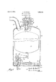
Still further objects will readily occur to those skilled in the art upon reference to the following description and the accompanying drawing in which The single figure on the drawing shows the float valve in section.
Referring to the drawing, it will be seen that the float valve includes a casing 10 closed by an upper head end 12 integral with the side wall of the casing and having a bottom 14 held in by and disposed between the clamps 16 and the inturned end 18 of the casing side wall. Disposed within the casing is a float 20 pivotally connected at 22 to a lever 24 which is pivotally mounted at 26 on the block 28 forming a part of the float valve bottom 14. Pivotally mounted to the lever 24 at the point 30 is a valve stem 32 having a needle point plug valve 34 adapted to close the port 36 in the plug 37 which provides communication, thru the lateral passages 38, between the interior of the casing 10 and the outlet tube 40. The main inlet for the float valve is thru the tube 42 whose end is covered by a mesh screen 44.
Disposed within the head 12 is an auxiliary valve which forms an important part of the invention. The auxiliary valve includes a sleeve welded, soldered or otherwise sealed and secured to the end 12, and having therein a bore 52 which is provided with lateral passages 54 connecting the bore with the interior of the eas- The sleeve is further provided with an internally threaded counterbore 56 which forms at 58, an annular valve seat. Threaded into the 50 counterbore 56 is a plug 60 having a bore 62 and lateral passages 64 connected thereto and opening to the tapered plug valve end 66 of the plug. The upper end of the plug is provided with a slot 68 adapted to receive a screw driver so that the plug may be moved in or out of the bore to engage or relieve itself of the seat 58 so as to close or open the sleeve bore 52, as desired.
The upper end of the sleeve is formed with a sharp, annular edge '70 and on the outside of the sleeve there is a thread '72 by means of which a cap 74 may be threaded onto the sleeve and close the latter, so as to conceal the plug valve and the bore 62, the
head of the cap 74 engaging the sharp ring 70 to form an auxiliary seal.
It will be seen that when it is desired to introduce an auxiliary supply of fluid into the casing 10 the operator can remove the cap 74 and then can rotate the plug 60 a few turns so as to relieve the valve seat 58. troduce the fluid into the sleeve, the tapered ring He can then inthe float 20, the latter upwardly extending ele head 80 disposed within being provided with an ment '78 having a ball the bore 52. It will be seen that as the float rises or falls with the level of the liquid, the element 78 and head 80 will ride in the bore 52 and will cause the float to be guided in its movement.
Now having described the invention and the preferred embodiment thereof, it is to be understood that the said invention is to be limited, not to the specific details herein set forth, but only by the scope of the claim which follows.
What I claim is:
A receptacle closure and filling device comprising a sleeve secured to the receptacle wall, the
sleeve having a bore and a counterbore, a plug in said counterbore engaging the inner wall of the sleeve on the annular edge at the upper end of the bore to close the latter, the plug having a reduced end partially entering said bore and a bore having lateral pass ages opening to said reduced end above the sleeve bore, and a cap on said sleeve, the upper end of the sleeve being outwardly flared and tapered to form a valve element adapted to coact with the cap to seal the upper end of the sleeve.
CURTIS M. BROWN.
Priority Applications (1)
| Application Number | Priority Date | Filing Date | Title |
|---|---|---|---|
| US519395A US1966706A (en) | 1931-03-02 | 1931-03-02 | Vent sealing means |
Applications Claiming Priority (1)
| Application Number | Priority Date | Filing Date | Title |
|---|---|---|---|
| US519395A US1966706A (en) | 1931-03-02 | 1931-03-02 | Vent sealing means |
Publications (1)
| Publication Number | Publication Date |
|---|---|
| US1966706A true US1966706A (en) | 1934-07-17 |
Family
ID=24068140
Family Applications (1)
| Application Number | Title | Priority Date | Filing Date |
|---|---|---|---|
| US519395A Expired - Lifetime US1966706A (en) | 1931-03-02 | 1931-03-02 | Vent sealing means |
Country Status (1)
| Country | Link |
|---|---|
| US (1) | US1966706A (en) |
Cited By (2)
| Publication number | Priority date | Publication date | Assignee | Title |
|---|---|---|---|---|
| US2764172A (en) * | 1951-10-22 | 1956-09-25 | Northrop Aircraft Inc | Air venting valve |
| US20080237235A1 (en) * | 2006-12-06 | 2008-10-02 | Weston Morabito | Resealable beverage container |
-
1931
- 1931-03-02 US US519395A patent/US1966706A/en not_active Expired - Lifetime
Cited By (3)
| Publication number | Priority date | Publication date | Assignee | Title |
|---|---|---|---|---|
| US2764172A (en) * | 1951-10-22 | 1956-09-25 | Northrop Aircraft Inc | Air venting valve |
| US20080237235A1 (en) * | 2006-12-06 | 2008-10-02 | Weston Morabito | Resealable beverage container |
| US7918363B2 (en) * | 2006-12-06 | 2011-04-05 | Weston Morabito | Resealable beverage container |
Similar Documents
| Publication | Publication Date | Title |
|---|---|---|
| US3460721A (en) | Valve for selective withdrawal of liquid or vapor | |
| US1998913A (en) | Faucet | |
| US2529275A (en) | Two-port valve for volatile liquid containers | |
| US1918807A (en) | Vent valve | |
| US1966706A (en) | Vent sealing means | |
| US2152831A (en) | Valve | |
| US2414113A (en) | Test means for high-pressure fluid medium containers | |
| US3095899A (en) | Liquid outage connection | |
| US1854051A (en) | Waterworks tap | |
| US2548352A (en) | Combined filling and dispensing valve for volatile liquids | |
| US2967541A (en) | Liquefied gas filler valve assembly | |
| US2540298A (en) | Valve | |
| US2331729A (en) | Direct draw faucet assembly | |
| US2656850A (en) | Excess flow check valve with manual reset means | |
| US3164308A (en) | Containers for liquified fuel gas | |
| US2387011A (en) | Tank gauge and filling device | |
| US2724404A (en) | Inlet valve | |
| US3211194A (en) | Filling valve | |
| US3469597A (en) | Safety device for limiting the amount of gas discharged from a container containing a liquefied gas to a predetermined volume | |
| US2308791A (en) | Liquid level gauge | |
| US2314273A (en) | Liquid tapping and blowing loss eliminator | |
| US1970074A (en) | Float valve | |
| US2231448A (en) | Means for tapping a high pressure line or container | |
| US2127731A (en) | Spraying apparatus | |
| US2234386A (en) | Valve for shampoo hoses and the like |