US1960883A - Telephone system - Google Patents
Telephone system Download PDFInfo
- Publication number
- US1960883A US1960883A US503981A US50398130A US1960883A US 1960883 A US1960883 A US 1960883A US 503981 A US503981 A US 503981A US 50398130 A US50398130 A US 50398130A US 1960883 A US1960883 A US 1960883A
- Authority
- US
- United States
- Prior art keywords
- relay
- line
- stations
- contact
- station
- Prior art date
- Legal status (The legal status is an assumption and is not a legal conclusion. Google has not performed a legal analysis and makes no representation as to the accuracy of the status listed.)
- Expired - Lifetime
Links
- 238000004804 winding Methods 0.000 description 15
- 239000004020 conductor Substances 0.000 description 4
- 238000003780 insertion Methods 0.000 description 2
- 230000037431 insertion Effects 0.000 description 2
- 244000025254 Cannabis sativa Species 0.000 description 1
- 238000000034 method Methods 0.000 description 1
- 230000011664 signaling Effects 0.000 description 1
Images
Classifications
-
- H—ELECTRICITY
- H04—ELECTRIC COMMUNICATION TECHNIQUE
- H04Q—SELECTING
- H04Q3/00—Selecting arrangements
Definitions
- My invention relates to a telephone system for use at a switching center to make a connection from a calling line to any one of sevaral other lines without the aid of a manual operator.
- a feature of my invention is the use of alternating current for setting up the connection.
- Another feature of my invention is a provision whereby a calling line may wait on a busy called line until that line is free, when connection is established without further operation.k
- Another feature of my invention is the provision of means whereby a second call may be made by a calling line without separately releasing the connection to the iirst called line.
- a still further feature of my invention is the provision of means whereby one accidental or tion and the appended claims.
- K1 is a release key, which is to be operated when it is desired to disconnect, as when conversation with a called station is completed.
- Relay 1 is a pulse tuned relay, operative when electric impulses of the proper frequency, suchV as 110 Volt 60 cycle, are sent over the line.
- the function of relays 2 to 16 inclusive is to set up the connection between the calling and called station.
- Relays 17, 18, and 19 key K5 and key K6 are optional arrangements for releasing a call which has been set up, and may be used in place of the release key K1.
- station No. 1 which comprises the equipment shown in the drawings
- station No. 2 which comprises similar equipment (not shown).
- the station telephone equipment consisting of a transmitter T and receiver R attached to a cord terminating in a plug P is connected to the circuit by inserting the plug P in jack E.
- Key K2 which is a spring actuated impulse key, is caused to make one revolution, which makes and breaks contact 20 two times. Each time contact 20 is made a circuit is closed from ground at contact 20, through the winding of relay G to battery, which operates relay G once for each closure of contact 20, or two times when key K2 is actuated.
- relay G closes a circuit for alternating current from current source 24 through alternate contacts 25 and 26 of relay G and the primary winding of repeating coil 27.
- the induced current in the secondary winding ofrrepeating coil 27 operates pulse tuned relay 1, through a circuit traced through line 28, upper normal contact 30 of relay 5, winding of relayl, lower-normal contact 31 of relay 5 and line 29.
- Relay 1 which is tuned to vibrate in response to the current supplied at 24, operates relay 2 through an obvious circuit.
- Relay 2 holds up during the pulsing period, operating relay 3 through an obvious circuit, and fallsoif during the interval between pulses.
- Relay 3 is a slow release relay, and holds up between pulses, talling on? after the last pulse is given.
- Relay 3 pulling up supplies ground from contact 31 of relay 2 to Aoperate relay 10, through a circuit traced through line 32, alternate contact 33 of relay 3, line 34, normal contact 35 ci relay 9, line 36, normal contact 37 of relay 11, line 38 to battery through the windingof relay 10.
- Relay 10 operates and locks to ground through the winding of relay 11, line 39, alternate contact 40 of relay 10 and normal contact 41 of relay 9.
- the operation of relay 11 transfers ground from relay 2 on the second impulse through alternate contact 42 of relay 11 to relays 12 and 13, which operate similarly to relays 10 and 11.
- the third impulse will be transferred to relays 14 and 15, andy any number of stations may be called in a similar manner by providing additional impulse keys vand 'additional relays corresponding to relays 10 and 11.
- the last station which is shown as party 4 in the drawings, is provided with one relay 16, which corresponds to relay 10 of station 2.
- Relay 16 is double wound, and locks to ground through its own contact. A relay corresponding to relay 11 is not required at the last station, as no further impulses are transmitted after relay 16 is actuated.
- relay 3 the operation of this relay breaks ground at normal contact 43, which opens the operating circuit of relay 9, closed by the operation of alternate contact 44 of relay 11 through contact 47, relay 9, line 46 and line 45.
- relay 3 falls off, closing the circuit for the operation of relay 9.
- This circuit is traced from ground at contact 43 of relayV 3 through line 45, line 46, normal contact 47, line 48, alternate contact 44, line 49, winding of relay 9 to battery.
- Relay 9 pulls up and locks to ground at contact 50 under control of relay 11.
- relay 6 will operate through a circuit traced from battery at relay 6, both windings of relay 6, line 51, alternate contact 52, line 53, contact 54, line 55, contact 56, line 57, alternate contact 58, line 59,k (which connects to line 60 of called station) to ground through line 60, relay 5, line 61 and contact 62 of relay 10 at the called station.
- Relay 6 shunts out its upper Winding by the closure of contact 63 and operates relay 5 of the called station through a circuit traced from battery through the lower winding of relay 6, alternate contact 63, line 51, alternate contact 52, line 53, contact l54, line 55, contact 56, line 57, alternate contact 58, and line 59 of the calling station, and line 60, Winding of relay 5, line 61, and contact 62 of relay 10, at the called station to ground.
- the operation of relay 6 also closes the talking circuit (designated on the drawings by heavy lines) at contacts 64, 65 and 66.
- Relay 5 of the called station opens the circuit for its relay 1, and the shunting of the upper winding of relay 6 or the calling lines prevents the connection of relay 6 of another calling line to a busy called line.
- the operation of relay 6 of the calling line also operates relay 7 through a circuit traced from ground at relay 6, alternate contact 67, line 68, line 69, normal contact 70, line 71 and winding of relay 7 to battery.
- Relay 7 operates, opening the talking circuit at normal contacts 72 and 73, and connecting signalling current to the called line from source RC through alternate contacts 72-73, the heavily marked conductors, normal contacts 101 and 102 of relay 16, normal contacts 103 and 104 of relay 14, alternate contacts 105 and 106 of relay 12, conductors 107 and 108 of the calling line which lead to conductors 109 and 110 of the called line, normal contacts 64 and 65 of relay 6, conductors 28 and 29, repeating coil 27,V normal contacts 25 and 26 of relay G, contacts of jack E thereby giving a signal such as ringing a bell or causing the operation of drop F at the called station.
- relay 7 also furnishes ground for the operation of relay 8, traced from ground through contact 67, line 68, alternate contact 74, line 75, winding of relay 8 to battery.
- Relay 8 operating opens the circuit for relay 7 at contact 70, but relay 7 is slow to release, and holds up long enough for a single impulse of ringing current, as described.
- Relay 8 locks up at alternate contact 70, and relay 7 falls back to close the talking circuit atnormal contacts 72 and 73. Should the calling party wish to repeat the ringing signal, this may be done by providing al source of ringing current, such as a hand generator, in connection with the station telephone equipment. This current may be of any frequency except that used to operate the kpulse-tuned relay 1.
- the line is now prepared for conversation upon the insertion of a plug into jack E of the called station.
- relay 4 of the calling station operates through a circuit traced from battery, winding of relay 4, line 76, alternate contact 77, line 78, normal contact 67 to ground.
- the operation of relay 4 places a busy tone from source BY to the callingline through contacts 79 and 80.
- the calling party Wish to wait to be connected to Ythe busy line, he may do so, and when the called line becomes idle, its relay 10 will fall olf, furnishing ground at contact 62 for the operation of relay 6 of the calling station, as previously described.
- the operation of relay 6 then opens the circuit for relay 4, at normal contact 67.
- the busy tone is removed from the calling line and the connection set up as previously described for a call to an idle line.
- Relay 1 operates relays 2 and 3, as for an original call.
- the operation of relay 3 breaks ground at contact 43, releasing all relays 10 to 16 inclusive which lare operated.
- the release of relay 11 breaks ground at contact 44, releasing relay 9, relay 9 breaks ground from relay 5 in called station at contact 52, releasing relay 6 of calling station and relay 5 of called station.
- Relay 6 breaks ground at contact 67releasing relay 8. Relays 1, 2 and 3 restore at the end of the impulse and the line is normal.
- K5 and K6 provide optional methods for releasing the equipment at the termination of a call.
- K5 is a manually operated non-locking key. Depression of key K5 operates relay 17 through a circuit traced' from ground through ,alternate contacts 81 and 82, line 83 and the winding of relay 17 to battery.
- Relay 17 operates relay 18 .and relay 18 operates relay 19 through obvious circuits.
- the release of key K5 provides ground traced from'normal contacts 81 and 82, line 84, contact 85 and line 86 for operation of relay G as described for operation of a disconnect by key K1.
- Relays 17, 18 and 19 are slow to release, and contact 85 is held closed a sufcient length of time to operate the necessary relays for release of the call.
- K6 may be an eXtra local contact on jack E, in which case insertion of the plug in jack E actuates contact K6 which in turn operates relay 17 and the associated equipment in the manner described for key K5.
- ground is applied to relay G through contact 85 to send a release pulse the same as described in the operation of key K5.
- a telephone system comprising a plurality of stations, sending means for transmitting impulses of alternating current and a plurality of relays individually associated with each of said stations, said relays being responsive successively to actuation of said sending means, and a circuit for joining a calling station to a predetermined called station closed incident to the actuation of said relays.
- a telephone system comprising a plurality of stations interchangeable as calling or called stations, calling means individual to each of said stations, said calling means comprising a device for transmitting impulses of alternating current and a series of relays responsive thereto and a circuit for joining a calling station to a predetermined called station closed incident to the actuation of a selected number of said relays.
- a telephone system comprising a plurality of stations interchangeable as calling and called stations, means individual to each station comprising an impulse device and a series of relays including a pulse-tuned alternating current relay operable a predetermined number of times for establishing connection between a calling and a predetermined called station.
- a telephone system comprising stations interchangeable as calling and called stations, a plurality of impulse sending devices at each of said stations, relays including an alternating current relay associated with each of said stations and operable a predetermined number of times, said relays being responsive to actuation of one of said impulse sending devices to close a circuit between a calling and a called station.
- a telephone system comprising stations interchangeable as calling and called stations, a plurality of impulse sending devices at each of said stations, relays including an alternating current relay associated with each of said stations, said relays being responsive to actuation of one of said impulse sending devices to close a circuit between a calling and a predetermined called station, and means responsive to the sending of a single impulse to restore the actuated relays to normal.
- a telephone system comprising stations interchangeable as calling and called stations, a plurality of impulse sending devices at each of said stations, relays including an alternating current relay associated with each of said stations,
- relays being selectively responsive to actua-y tion of one of said impulse sending devices to close a circuit between a calling and a predetermined called station, and means responsive to the actuation of another of said impulse sending devices to restore the actuated relays to normal and institute a call to another wanted station.
- a telephone system comprising a plurality of subscriber stations, station selecting mechanism individual to each of said subscriber stations, a transformer interposed between each of said stations and said station selecting mechanism, alternating ciuirent means associated with the input side of said transformer and an alternating current relay associated with the output of said transformer for controlling said station selecting mechanism.
- a telephone system comprising a plurality of subscriber stations, station selecting mechanism individual to each of said subscriber stations, a transformer interposed between each of said stations and said station selecting mechanism, a1-
- ternating current means associated with the input side of said transformer and an alternating current relay associated with the output of said transformer, a group of direct current relays included in said station selecting mechanism controlled by said alternating current relay for interconnecting two of said stations.
- a telephone system comprising a plurality of subscriber stations, station selecting mechanism individual to each of said subscriber stations, a transformer, alternating current means associated with each side of said transformer, a group of relays controlled by said alternating current means for connecting two of said stations, a talking circuit for said stations including said transformer.
- a telephone system comprising a plurality of subscriber stations, an impulse sending device at each of said stations, station selecting mechanism for joining any one of said stations: to a desired other station, a transformer interposed betweenV said one of said stations and Said station selecting mechanism, a source of alternating current, means responsive to the actuation of said sending device for intermittently joining said source to the input side of said transformer and an alternating current relay associated with the output side of said transformer for controlling the operation of said station selecting mechanism.
- a telephone system comprising stations interchangeable as calling and called stations, an impulse sending device at each of said stations, relays associated with each of said impulse sending devices. to close a circuit between a calling and a predetermined called station, and means responsive to the sending of a single impulse to restore the actuated relays to normal.
- a telephone system comprising stations interchangeable as calling and called stations, an impulse sending device at each of said stations, relays including an alternating current relay associated with cach of said stations, said relays being responsive to the actuation of said impulse sending ⁇ device to close a circuit between a calling and predetermined called station, and means responsive to the sending of a single impulse to restore the actuated relays to normal.
- a telephone system comprising stations interchangeable as calling and called stations, an impulse sending device at each of said stations, relays including an alternating current relay associated with each of said stations, said relays being selectively responsive to the actuation of one of said impulse sending devices to close a circuit between a calling and a predetermined called station, and means responsive to the actuation of another of said impulse sending devices to restore the actuated relays to normal and institute a call toanother wanted station.
- a telephone system comprising stations interchangeable as calling and called? stations, an impulse sending device at each of said stations, relays associated with each of said stations selectively responsive to the actuation of the impulse sending device associated therewith to close a circuit between a calling and a predetermined called station, and means responsive to the actuation of any impulse sending device to restore the actuated relays to normal and institute a call to another wanted station.
Landscapes
- Engineering & Computer Science (AREA)
- Computer Networks & Wireless Communication (AREA)
- Devices For Supply Of Signal Current (AREA)
Description
B. A. WALLACE TELEPHONE SYSTEM May 29, 1934.
2 Sheets-Sheet 1 Filed Dec.
| l l l l lllmmm.
l/En Dr BEI-"T HDL/allaite May 29, 1934- B.VA. WALLACE TELEPHONE SYSTEM Filed Dec. 22, 1950 2 Sheets-Sheet 2 INU] Patented May 29, 1934 grass TELEPHONE SYSTEM Bert A. Wallace, Chicago, Ill., assignor to Kellogg Switchboard and Supply Company, Chicago, Ill., a corporation of Illinois f Application December 22, 1930, serial No. 503,981
14 claims. (c1. 179-37) My invention relates to a telephone system for use at a switching center to make a connection from a calling line to any one of sevaral other lines without the aid of a manual operator.
A feature of my invention is the use of alternating current for setting up the connection.
Another feature of my invention is a provision whereby a calling line may wait on a busy called line until that line is free, when connection is established without further operation.k
Another feature of my invention is the provision of means whereby a second call may be made by a calling line without separately releasing the connection to the iirst called line.
A still further feature of my invention is the provision of means whereby one accidental or tion and the appended claims.
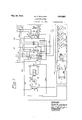
' and K4 are keys used to call the other stations on the line, each key being arranged to signal a particular station. Though I have illustrated three keys, it is to be understood that any number may be used, one for each station. K1 is a release key, which is to be operated when it is desired to disconnect, as when conversation with a called station is completed. Relay 1 is a pulse tuned relay, operative when electric impulses of the proper frequency, suchV as 110 Volt 60 cycle, are sent over the line. The function of relays 2 to 16 inclusive is to set up the connection between the calling and called station. Relays 17, 18, and 19, key K5 and key K6 are optional arrangements for releasing a call which has been set up, and may be used in place of the release key K1.
It is believed that the circuit will be more readily understood by a detailed description of its operation, which follows.
Assuming that it is desired to make a connection between station No. 1, which comprises the equipment shown in the drawings, and station No. 2, which comprises similar equipment (not shown). The station telephone equipment consisting of a transmitter T and receiver R attached to a cord terminating in a plug P is connected to the circuit by inserting the plug P in jack E. Key K2, which is a spring actuated impulse key, is caused to make one revolution, which makes and breaks contact 20 two times. Each time contact 20 is made a circuit is closed from ground at contact 20, through the winding of relay G to battery, which operates relay G once for each closure of contact 20, or two times when key K2 is actuated.
The operation of relay G closes a circuit for alternating current from current source 24 through alternate contacts 25 and 26 of relay G and the primary winding of repeating coil 27. The induced current in the secondary winding ofrrepeating coil 27 operates pulse tuned relay 1, through a circuit traced through line 28, upper normal contact 30 of relay 5, winding of relayl, lower-normal contact 31 of relay 5 and line 29. Relay 1, which is tuned to vibrate in response to the current supplied at 24, operates relay 2 through an obvious circuit. Relay 2 holds up during the pulsing period, operating relay 3 through an obvious circuit, and fallsoif during the interval between pulses. Relay 3 is a slow release relay, and holds up between pulses, talling on? after the last pulse is given. Relay 3 pulling up supplies ground from contact 31 of relay 2 to Aoperate relay 10, through a circuit traced through line 32, alternate contact 33 of relay 3, line 34, normal contact 35 ci relay 9, line 36, normal contact 37 of relay 11, line 38 to battery through the windingof relay 10. Relay 10 operates and locks to ground through the winding of relay 11, line 39, alternate contact 40 of relay 10 and normal contact 41 of relay 9. At the end of the rst impulse relay 2 falls off, removing the ground which has shunted relay 11, and relay 11 operates and locks through the locking circuit for relay 10. The operation of relay 11 transfers ground from relay 2 on the second impulse through alternate contact 42 of relay 11 to relays 12 and 13, which operate similarly to relays 10 and 11. Should key K3 be operated instead of key K2, the third impulse will be transferred to relays 14 and 15, andy any number of stations may be called in a similar manner by providing additional impulse keys vand 'additional relays corresponding to relays 10 and 11. As the operation of such circuits would be a repetition of what has already been described, it is not considered necessary to describe each in detail. The last station, which is shown as party 4 in the drawings, is provided with one relay 16, which corresponds to relay 10 of station 2. Relay 16 is double wound, and locks to ground through its own contact. A relay corresponding to relay 11 is not required at the last station, as no further impulses are transmitted after relay 16 is actuated.
Referring again to relay 3, the operation of this relay breaks ground at normal contact 43, which opens the operating circuit of relay 9, closed by the operation of alternate contact 44 of relay 11 through contact 47, relay 9, line 46 and line 45. When the pulsing has been completed relay 3 falls off, closing the circuit for the operation of relay 9. This circuit is traced from ground at contact 43 of relayV 3 through line 45, line 46, normal contact 47, line 48, alternate contact 44, line 49, winding of relay 9 to battery. Relay 9 pulls up and locks to ground at contact 50 under control of relay 11. A Y
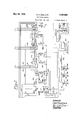
If the called line is idle, relay 6 will operate through a circuit traced from battery at relay 6, both windings of relay 6, line 51, alternate contact 52, line 53, contact 54, line 55, contact 56, line 57, alternate contact 58, line 59,k (which connects to line 60 of called station) to ground through line 60, relay 5, line 61 and contact 62 of relay 10 at the called station. Relay 6 shunts out its upper Winding by the closure of contact 63 and operates relay 5 of the called station through a circuit traced from battery through the lower winding of relay 6, alternate contact 63, line 51, alternate contact 52, line 53, contact l54, line 55, contact 56, line 57, alternate contact 58, and line 59 of the calling station, and line 60, Winding of relay 5, line 61, and contact 62 of relay 10, at the called station to ground. The operation of relay 6 also closes the talking circuit (designated on the drawings by heavy lines) at contacts 64, 65 and 66. Relay 5 of the called station opens the circuit for its relay 1, and the shunting of the upper winding of relay 6 or the calling lines prevents the connection of relay 6 of another calling line to a busy called line. The operation of relay 6 of the calling line also operates relay 7 through a circuit traced from ground at relay 6, alternate contact 67, line 68, line 69, normal contact 70, line 71 and winding of relay 7 to battery. Relay 7 operates, opening the talking circuit at normal contacts 72 and 73, and connecting signalling current to the called line from source RC through alternate contacts 72-73, the heavily marked conductors, normal contacts 101 and 102 of relay 16, normal contacts 103 and 104 of relay 14, alternate contacts 105 and 106 of relay 12, conductors 107 and 108 of the calling line which lead to conductors 109 and 110 of the called line, normal contacts 64 and 65 of relay 6, conductors 28 and 29, repeating coil 27,V normal contacts 25 and 26 of relay G, contacts of jack E thereby giving a signal such as ringing a bell or causing the operation of drop F at the called station. The operation of relay 7 also furnishes ground for the operation of relay 8, traced from ground through contact 67, line 68, alternate contact 74, line 75, winding of relay 8 to battery. Relay 8 operating opens the circuit for relay 7 at contact 70, but relay 7 is slow to release, and holds up long enough for a single impulse of ringing current, as described. Relay 8 locks up at alternate contact 70, and relay 7 falls back to close the talking circuit atnormal contacts 72 and 73. Should the calling party Wish to repeat the ringing signal, this may be done by providing al source of ringing current, such as a hand generator, in connection with the station telephone equipment. This current may be of any frequency except that used to operate the kpulse-tuned relay 1. The line is now prepared for conversation upon the insertion of a plug into jack E of the called station.
Should the called station Ybe busy on an outgoing call, its relay 10 will be operated, and ground Will'fnot be supplied at contact 62 for operation of relay l6 of al calling station. In this case relay 4 of the calling station operates through a circuit traced from battery, winding of relay 4, line 76, alternate contact 77, line 78, normal contact 67 to ground. The operation of relay 4 places a busy tone from source BY to the callingline through contacts 79 and 80. Should the calling party Wish to wait to be connected to Ythe busy line, he may do so, and when the called line becomes idle, its relay 10 will fall olf, furnishing ground at contact 62 for the operation of relay 6 of the calling station, as previously described. The operation of relay 6 then opens the circuit for relay 4, at normal contact 67. The busy tone is removed from the calling line and the connection set up as previously described for a call to an idle line.
When conversation is completed the connection is released by operation ofthe release key K1 by either the calling or called party. The operation o-f this key `makes and breaks contact 23 once, causing relay G to pull up and fall back once. l, 2 and 3, as described for making a call. Relay 1 operates relays 2 and 3, as for an original call. The operation of relay 3 breaks ground at contact 43, releasing all relays 10 to 16 inclusive which lare operated. The release of relay 11 breaks ground at contact 44, releasing relay 9, relay 9 breaks ground from relay 5 in called station at contact 52, releasing relay 6 of calling station and relay 5 of called station. Relay 6 breaks ground at contact 67releasing relay 8. Relays 1, 2 and 3 restore at the end of the impulse and the line is normal.
Should either party desire to set up a new call immediately, this may be done without a separate disconnect operation. If any of the calling keys is actuated-instead of the release key, the rst impulse sent over the line operates to disconnect the connection, as described in the preceding paragraph, and the impulse is of sufli- The operation of relay G operates relays cient length Vto perform the irst step required v for the new call, after the release.
Keys K5 and K6 provide optional methods for releasing the equipment at the termination of a call. K5 is a manually operated non-locking key. Depression of key K5 operates relay 17 through a circuit traced' from ground through ,alternate contacts 81 and 82, line 83 and the winding of relay 17 to battery. Relay 17 operates relay 18 .and relay 18 operates relay 19 through obvious circuits. The release of key K5 provides ground traced from'normal contacts 81 and 82, line 84, contact 85 and line 86 for operation of relay G as described for operation of a disconnect by key K1. Relays 17, 18 and 19 are slow to release, and contact 85 is held closed a sufcient length of time to operate the necessary relays for release of the call. K6 may be an eXtra local contact on jack E, in which case insertion of the plug in jack E actuates contact K6 which in turn operates relay 17 and the associated equipment in the manner described for key K5. When plug is removed from jack E at the end of a connection, ground is applied to relay G through contact 85 to send a release pulse the same as described in the operation of key K5.
While I have described and shown a preferred embodiment of my invention it is to be understood that changes and modications Will readily suggest themselves to those skilled in the art, and I, therefore, desire to be limited only by the spirit and scope of the appended claims.
Having described my invention, what I claim as new and desire to secure by United States Letters Patent is:
1. A telephone system comprising a plurality of stations, sending means for transmitting impulses of alternating current and a plurality of relays individually associated with each of said stations, said relays being responsive successively to actuation of said sending means, and a circuit for joining a calling station to a predetermined called station closed incident to the actuation of said relays.
2. A telephone system comprising a plurality of stations interchangeable as calling or called stations, calling means individual to each of said stations, said calling means comprising a device for transmitting impulses of alternating current and a series of relays responsive thereto and a circuit for joining a calling station to a predetermined called station closed incident to the actuation of a selected number of said relays.
3. A telephone system comprising a plurality of stations interchangeable as calling and called stations, means individual to each station comprising an impulse device and a series of relays including a pulse-tuned alternating current relay operable a predetermined number of times for establishing connection between a calling and a predetermined called station.
4. A telephone system comprising stations interchangeable as calling and called stations, a plurality of impulse sending devices at each of said stations, relays including an alternating current relay associated with each of said stations and operable a predetermined number of times, said relays being responsive to actuation of one of said impulse sending devices to close a circuit between a calling and a called station.
5. A telephone system comprising stations interchangeable as calling and called stations, a plurality of impulse sending devices at each of said stations, relays including an alternating current relay associated with each of said stations, said relays being responsive to actuation of one of said impulse sending devices to close a circuit between a calling and a predetermined called station, and means responsive to the sending of a single impulse to restore the actuated relays to normal.
6. A telephone system comprising stations interchangeable as calling and called stations, a plurality of impulse sending devices at each of said stations, relays including an alternating current relay associated with each of said stations,
said relays being selectively responsive to actua-y tion of one of said impulse sending devices to close a circuit between a calling and a predetermined called station, and means responsive to the actuation of another of said impulse sending devices to restore the actuated relays to normal and institute a call to another wanted station.
7. A telephone system comprising a plurality of subscriber stations, station selecting mechanism individual to each of said subscriber stations, a transformer interposed between each of said stations and said station selecting mechanism, alternating ciuirent means associated with the input side of said transformer and an alternating current relay associated with the output of said transformer for controlling said station selecting mechanism.
8. A telephone system comprising a plurality of subscriber stations, station selecting mechanism individual to each of said subscriber stations, a transformer interposed between each of said stations and said station selecting mechanism, a1-
ternating current means associated with the input side of said transformer and an alternating current relay associated with the output of said transformer, a group of direct current relays included in said station selecting mechanism controlled by said alternating current relay for interconnecting two of said stations.
9. A telephone system comprising a plurality of subscriber stations, station selecting mechanism individual to each of said subscriber stations, a transformer, alternating current means associated with each side of said transformer, a group of relays controlled by said alternating current means for connecting two of said stations, a talking circuit for said stations including said transformer.
10. A telephone system comprising a plurality of subscriber stations, an impulse sending device at each of said stations, station selecting mechanism for joining any one of said stations: to a desired other station, a transformer interposed betweenV said one of said stations and Said station selecting mechanism, a source of alternating current, means responsive to the actuation of said sending device for intermittently joining said source to the input side of said transformer and an alternating current relay associated with the output side of said transformer for controlling the operation of said station selecting mechanism.
11. A telephone system comprising stations interchangeable as calling and called stations, an impulse sending device at each of said stations, relays associated with each of said impulse sending devices. to close a circuit between a calling and a predetermined called station, and means responsive to the sending of a single impulse to restore the actuated relays to normal.
12. A telephone system comprising stations interchangeable as calling and called stations, an impulse sending device at each of said stations, relays including an alternating current relay associated with cach of said stations, said relays being responsive to the actuation of said impulse sending `device to close a circuit between a calling and predetermined called station, and means responsive to the sending of a single impulse to restore the actuated relays to normal.
13. A telephone system comprising stations interchangeable as calling and called stations, an impulse sending device at each of said stations, relays including an alternating current relay associated with each of said stations, said relays being selectively responsive to the actuation of one of said impulse sending devices to close a circuit between a calling and a predetermined called station, and means responsive to the actuation of another of said impulse sending devices to restore the actuated relays to normal and institute a call toanother wanted station.
14. A telephone system comprising stations interchangeable as calling and called? stations, an impulse sending device at each of said stations, relays associated with each of said stations selectively responsive to the actuation of the impulse sending device associated therewith to close a circuit between a calling and a predetermined called station, and means responsive to the actuation of any impulse sending device to restore the actuated relays to normal and institute a call to another wanted station.
BERT A. WALLACE.
Priority Applications (1)
| Application Number | Priority Date | Filing Date | Title |
|---|---|---|---|
| US503981A US1960883A (en) | 1930-12-22 | 1930-12-22 | Telephone system |
Applications Claiming Priority (1)
| Application Number | Priority Date | Filing Date | Title |
|---|---|---|---|
| US503981A US1960883A (en) | 1930-12-22 | 1930-12-22 | Telephone system |
Publications (1)
| Publication Number | Publication Date |
|---|---|
| US1960883A true US1960883A (en) | 1934-05-29 |
Family
ID=24004345
Family Applications (1)
| Application Number | Title | Priority Date | Filing Date |
|---|---|---|---|
| US503981A Expired - Lifetime US1960883A (en) | 1930-12-22 | 1930-12-22 | Telephone system |
Country Status (1)
| Country | Link |
|---|---|
| US (1) | US1960883A (en) |
Cited By (1)
| Publication number | Priority date | Publication date | Assignee | Title |
|---|---|---|---|---|
| US2632056A (en) * | 1947-12-30 | 1953-03-17 | Rauland Corp | Busy signal for intercommunicating telephone systems |
-
1930
- 1930-12-22 US US503981A patent/US1960883A/en not_active Expired - Lifetime
Cited By (1)
| Publication number | Priority date | Publication date | Assignee | Title |
|---|---|---|---|---|
| US2632056A (en) * | 1947-12-30 | 1953-03-17 | Rauland Corp | Busy signal for intercommunicating telephone systems |
Similar Documents
| Publication | Publication Date | Title |
|---|---|---|
| US1960883A (en) | Telephone system | |
| US2564048A (en) | Carrier and radio termination for telephone circuits | |
| US1919317A (en) | Telephone system | |
| US2247507A (en) | Telephone system | |
| US2024581A (en) | Telegraph toll system | |
| US2183941A (en) | Signaling system | |
| US1575334A (en) | Telephone system | |
| US1747219A (en) | Telephone system | |
| US1859475A (en) | Call indicator system | |
| US2686841A (en) | Block coupler | |
| US1804408A (en) | Telephone exchange system | |
| US2842622A (en) | Carrier adapter circuit | |
| US810335A (en) | Telephone party-line system. | |
| US811692A (en) | Party telephone-line. | |
| US1917879A (en) | Telephone system | |
| US1902123A (en) | Control circuit for switches for automatic telephone systems | |
| US2161218A (en) | Rural line repeater | |
| US2617886A (en) | Multivoltage train telephone system | |
| US2880283A (en) | Trunk-test apparatus | |
| US1847137A (en) | Communication system | |
| US1324749A (en) | Telephone system. | |
| US1818064A (en) | Telephone system | |
| US1647258A (en) | Telephone system | |
| US1812641A (en) | Remote control magneto telephone system | |
| US2742529A (en) | Trunk and control circuits to semiautomatic magneto exchange |