US1951663A - Forced circulation heating system - Google Patents
Forced circulation heating system Download PDFInfo
- Publication number
- US1951663A US1951663A US606409A US60640932A US1951663A US 1951663 A US1951663 A US 1951663A US 606409 A US606409 A US 606409A US 60640932 A US60640932 A US 60640932A US 1951663 A US1951663 A US 1951663A
- Authority
- US
- United States
- Prior art keywords
- contact
- temperature
- relay
- heat
- circuit
- Prior art date
- Legal status (The legal status is an assumption and is not a legal conclusion. Google has not performed a legal analysis and makes no representation as to the accuracy of the status listed.)
- Expired - Lifetime
Links
- 238000010438 heat treatment Methods 0.000 title description 9
- 239000012530 fluid Substances 0.000 description 61
- 230000007246 mechanism Effects 0.000 description 17
- QSHDDOUJBYECFT-UHFFFAOYSA-N mercury Chemical compound [Hg] QSHDDOUJBYECFT-UHFFFAOYSA-N 0.000 description 4
- 229910052753 mercury Inorganic materials 0.000 description 4
- 230000008859 change Effects 0.000 description 3
- 230000005291 magnetic effect Effects 0.000 description 3
- 239000000446 fuel Substances 0.000 description 2
- 230000005484 gravity Effects 0.000 description 2
- 230000004048 modification Effects 0.000 description 2
- 238000012986 modification Methods 0.000 description 2
- 230000003472 neutralizing effect Effects 0.000 description 2
- 238000013021 overheating Methods 0.000 description 2
- 230000009467 reduction Effects 0.000 description 2
- 230000004044 response Effects 0.000 description 2
- 230000002441 reversible effect Effects 0.000 description 2
- 101100161752 Mus musculus Acot11 gene Proteins 0.000 description 1
- 208000003251 Pruritus Diseases 0.000 description 1
- 230000009471 action Effects 0.000 description 1
- 238000001816 cooling Methods 0.000 description 1
- 238000010586 diagram Methods 0.000 description 1
- 230000004907 flux Effects 0.000 description 1
- 230000006698 induction Effects 0.000 description 1
- 230000007803 itching Effects 0.000 description 1
- 230000005389 magnetism Effects 0.000 description 1
- 229920000136 polysorbate Polymers 0.000 description 1
- 230000008707 rearrangement Effects 0.000 description 1
- 230000003134 recirculating effect Effects 0.000 description 1
- 210000003813 thumb Anatomy 0.000 description 1
Images

Classifications
-
- F—MECHANICAL ENGINEERING; LIGHTING; HEATING; WEAPONS; BLASTING
- F23—COMBUSTION APPARATUS; COMBUSTION PROCESSES
- F23N—REGULATING OR CONTROLLING COMBUSTION
- F23N5/00—Systems for controlling combustion
- F23N5/02—Systems for controlling combustion using devices responsive to thermal changes or to thermal expansion of a medium
- F23N5/04—Systems for controlling combustion using devices responsive to thermal changes or to thermal expansion of a medium using bimetallic elements
- F23N5/045—Systems for controlling combustion using devices responsive to thermal changes or to thermal expansion of a medium using bimetallic elements using electrical or electromechanical means
-
- G—PHYSICS
- G05—CONTROLLING; REGULATING
- G05D—SYSTEMS FOR CONTROLLING OR REGULATING NON-ELECTRIC VARIABLES
- G05D23/00—Control of temperature
- G05D23/19—Control of temperature characterised by the use of electric means
- G05D23/1927—Control of temperature characterised by the use of electric means using a plurality of sensors
- G05D23/193—Control of temperature characterised by the use of electric means using a plurality of sensors sensing the temperaure in different places in thermal relationship with one or more spaces
- G05D23/1931—Control of temperature characterised by the use of electric means using a plurality of sensors sensing the temperaure in different places in thermal relationship with one or more spaces to control the temperature of one space
-
- G—PHYSICS
- G05—CONTROLLING; REGULATING
- G05D—SYSTEMS FOR CONTROLLING OR REGULATING NON-ELECTRIC VARIABLES
- G05D23/00—Control of temperature
- G05D23/19—Control of temperature characterised by the use of electric means
- G05D23/275—Control of temperature characterised by the use of electric means with sensing element expanding, contracting, or fusing in response to changes of temperature
-
- F—MECHANICAL ENGINEERING; LIGHTING; HEATING; WEAPONS; BLASTING
- F23—COMBUSTION APPARATUS; COMBUSTION PROCESSES
- F23N—REGULATING OR CONTROLLING COMBUSTION
- F23N2225/00—Measuring
- F23N2225/08—Measuring temperature
-
- F—MECHANICAL ENGINEERING; LIGHTING; HEATING; WEAPONS; BLASTING
- F23—COMBUSTION APPARATUS; COMBUSTION PROCESSES
- F23N—REGULATING OR CONTROLLING COMBUSTION
- F23N2233/00—Ventilators
- F23N2233/06—Ventilators at the air intake
Definitions
- the present invention relates to the type of heating system wherein the heat increasing 'means heats a fluid the circulation of which is controlled by a circulation controlling device.
- invention relates particularly to the control of 4 forced circulation hot air furnaces wherein the heated air is circulated by means of a blower device or fan.
- One of the primary objects of the invention is the provision of a control system for a forced circulation hot air furnace whereby upon a fall in room temperature the heat increasing means will be operated to supply heat to the air and the blower device will be operated to circulate the heated air to the room or space to be heated including provision for maintaining the operation of theblower device after the room temperature has been restored to normal if the air at the furnace is above a predetermined maximum temperature. Provision is also made to prevent operation of the blower device if the temperature of the circulated air is below a predetermined minimum temperature even though the space to be heated is at a temperature below that desired.
- a further object of the invention is to provide a control system for a forced circulation hot air furnace in which the blower device is operated to circulate heated air to the space to be heated when the temperature of the circulated air is sufliciently high upon a first fall in temperature in the space to be heated, to operate the heat increasing means for supplying heat to the circulated air upon a further drop in room temperature provided the temperature of the circulated air is not above .or does not rise above a predetermined maximum, to stop operation of the heat increasing means when the temperature of the space to be heated has been partially restored, and to subsequently stop operation of the blower device when the temperature of the space to be heated has been fully restored.
- a further object of the invention is to provide control systems such as outlined above which are relatively simple and are composed of standard apparatus that is available on the market.
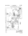
- Fig. 3 is a schematic wiring diagram showing a further type of control system which may be applied to the mechanism of Fig. 1;
- Fig. 4 is a schematic showing of a control system similar to the system of Fig. 1, but in which a slightly difierent type of relay unit is utilized;
- Fig. 5 is a detail of one of the devices diagrammatically shown in Fig. 1;
- Fig. 6 is a view showing details of the furnace switch of Pig. 1.
- a conventional type of hot air furnace indicated at 10 is provided with a cold air or recirculating air inlet indicated at 11.
- a motor 12 placed in the inlet 11 drives a fan 13 for circulating air through the furnace and into the space to be heated.
- the heat in: creasing means is herein shown as a burner 1-1 which is supplied with gas or other suitable combustible fluid by supply pipe 15 which in turn is controlled by a valve 16.
- the burner 14 is preferably supplied with a constantly burning pilotlight indicated at 17.
- the pilot 17 preferably heats a bimetallic element 18 which when hot engages a contact 19 whereby operation of the system is prevented in the event that the pilot goes out as will hereinafter be explained.
- Valve 16 is operated by an electric motor herein diagrammatically illustrated as being of the induction type as shown by the field coil 20 and rotor 21.
- Rotor 21 drives a gear 22 mounted upon a shaft 23 through reduction gearing generally indicated'at 24.
- Gear 22 carries a pin 25 near its periphery which pin is adapted to engage the hooked end portion 26 of a rod 27 upon rotation of gear 22 in a clockwise direction.
- the lower end of rod 2'! is pivotally secured to a lever 28 which in turn is pivoted as shown at 29.
- Valve stem 30 of valve 16 passes through lever 28 and 95 is provided with an enlarged head 31 which is held biased in engagement with lever 28 by p ing 32.
- gear 22 When field coil 20 is energized gear 22 is rotated clockwiseby means of rotor 21 and reduction gearing 24 whereupon pin 25 engages book 26 of rod 2'! which in turn lifts lever 28 and valve stem 30 against the bias of spring 32 to open valve 16 and allow flow of gas to burner 14.
- spring 32 closes valve 10 16, moves lever 28 and rod 27 downwardly, and .rotates gear 22 and rotor 21 in the reverse direction until the parts are brought back to their original position as shown in Fig. 1. no
- cam member 33 upon each side of which is positioned a friction washer 34.
- One of the friction washers 34 abuts a collar 35 on shaft 23 and the other friction washer 34 is engaged by one end of a coil spring 36 wound about shaft 23 and the other end of coil spring 36 presses against a washer 37, which is held in position on shaft 23 by cotter pin 38.
- the motion of cam member 33 is limited to a rather narrow range by a stationary pin 39 which cooperates with the edges of a recessed portion 40 formed in cam member 33.
- Cam member 33 is provided with a shoulder 41 upon which a cam follower 42 is adapted to ride when cam member 33 is rotated in a clockwise direction.
- Cam follower 42 is secured to a lever 43 pivoted at 44 which is normally biased into engagement with a contact 45 by means of tension spring 46.
- follower 42 rides up shoulder 41 contact arm '43 disengages contact 45 and ensages a contact 47.
- the control system includes a thermostatic switch (see Figs. 1 and 6) which comprises a casing 48 provided with a lateraltubular extension 49 which terminates within the bonnet of furnace 10. An.
- helically coiled bimetallic element 50 has one of its ends secured to extension 49 and has its other end secured to a rod 51 which extends through tubular extension 49 and terminates within casing 48. It will be obvious that bimetallic element 50 responds to the temrature of the air within the bonnet of furnace 0.
- Shaft 51 carries three cams 52, 53, and 54 which are adiustably secured to the shaft 51 by thumb nut 55.
- a bracket 56 is pivoted to casing 48 as shown at 57 and is provided with a down ward extension 58 which carries a roller 59.
- Bracket 56 is also provided with upwardly extending clips 60 which carry a mercury switch 61 which will be hereinafter referred. to as the high limit switch".
- pivot 57 is removed from the center of bracket 56 so that the weight of bracket 56 and high limit switch 61 always maintains roller 59 in contact with the periphery of cam 52.
- the cam 52 is provided with the shoulder 62 so that upon rotation of cam 52 in a counter-clockwise direction as a result of excessive temperature in the furnace 10, high limit switch 61 will be'allowed to rotate in a clockwise direction about its pivot 57 to open circuit posiiton.
- a bracket 63 which is pivoted to casing 48 as shown at 64 supports a mercury switch 65 which will hereinafter be referred to as the "fan switch".
- Bracket 63 is provided with upwardly extending arms 66 and 67 the former of which is adapted to be engaged by a shoulder 68 on cam 53 upon temperature riseand the latter of which is adapted to be engaged by a shoulder 69 on cam 54 on a temperature fall at bimetallic e1ement50.
- Inasmuchasfanswitch 65 hasits centraiportionsecuredtobmcket63.thisassembly will remain in either open or closed'position after having been moved thereto by shoulder 69 or shoulder 68. After having been moved to either open or closed position bracket 63 and fan switch 65 are prevented from rotating an undue amount by engagement of arm 66 or 67 as the case may be with the periphery of cam 53 or 54.
- the control system also includes a room thermostat comprising a bimetallic volute 70 to the free end of which are secured flexible contact blades 71 and 72.
- a room thermostat comprising a bimetallic volute 70 to the free end of which are secured flexible contact blades 71 and 72.
- flexible blade '11 On a lowering of room temperature flexible blade '11 first engages the contact 73' and subsequently flexible blade 72 engages contact 74.
- contact 74 When the room temperature rises flexible blade 72 first leaves contact 74, flexible blade 71 subsequently leaves contact 73 and when the room temperature has been restored to normal flexible blade 71 engages a contact 75.
- the control system also includes a standard relay means of the double coil type.
- Coil 76 upon energization attracts armature 77 which in turn moves switch arms 78, 79, and 80 into engagement with contacts 81, 82, and 83.
- a bucking coil 84 when energized neutralizes the magnetic effect of coil 76 thereby allowing armature 77 to move to the position of Fig. 1 under the action of gravity.
- Operation gage contact 73 which establishes an energizing circuit for coil 76 as follows: secondary 89, wires 91, 92, element 70, blade 71, contact 73, wire 93, contact arm 43, contact 45, wire 94', coil 76, and wire 95 to" secondary 89.
- Energization of coil 76 attracts armature '77 and moves switch arms 78, 79, and 80 into engagement with contacts- 81, 82, and 83.
- Engagement of contact arm 80 with contact 83 establishes the following holding circuit for coil 76: secondary 89, wires 91, 96, contact arm 30, contact 83, wire 97, coil 76, and wire 95 to secondary 89.
- the fan switch 65 would be in open circuit position and fan motor 12 would not be energized.
- contact blade 72 will engage contact 74 to establish an energizing circuit for fleld .20 as follows: secondary 90, wire 102, element 18, contact 19, wire 103, high limit switch 61, wire 104, element 70, blade 72, contact 74, wire 105, wire 106, field 20, and wire 107 to secondary 90. It will be seen that this energizing circuit for field 20 includes element 18 and contact 19 so that valve 16 can not be opened if pilot 17 is extinguished. Energization of field 20 opens valve 16 as hereinbefore described and gas is supplied to burner 14 and ignited by pilot 1'7.
- Opening of valve 16 also moves contact arm 43 from engagement with contact 45 and into engagement with contact 4'7.
- Engagement of contact arm 43 with contact 4'! establishes a holding circuit for field 20 which is as follows: secondary 90, 102, 18, 19, '103, 61, 104, '70, blade '71, contact '73, wire 93, contact arm 43, contact 47, wire 108, 106, field 20, and 107 to secondary 90. It will be seen that energization of field 20 is accomplished by engagement of blade '72 with contact '74, but that field 20 is maintained energized by the holding circuit just described until blade '71 leaves contact '73.
- Coil 84 when energized creates a magnetic fiux equal and opposite to the magnetic flux created by coil '76.
- the effective magnetism on armature '77 is zero so that armature '77 and its associated switch arms '78, '79, and 80 will move to the position of Fig. 1 under the influence of gravity bringing the system back to its original condition.
- Fig. 1 From the foregoing description of Fig. 1 it will be observed that on a first fall in temperature the fan 13 is operated to remove any heat from furnace 10 that might be present. If this heat is sufilcient to restore the room temperature so that blade '71 engages contact '75, fan 13 will cease operating. If there is no heat in the furnace, operation of fan 13 is prevented by means of fan switch 65. If there is no heat in the furnace so that fan 18 can not be operated or if the heat present in the furnace is not sufllcient to prevent a further fall in room temperature, blade '72 engages contact '74 and valve 16 is opened to supply fuel to burner 14 provided pilot 17 is not extinguished.
- Valve 16 will remain open until the room temperature has been partially restored so as to cause blade '71 to leave contact '73 provided the furnace temperature is not or does not become excessive in which case high limit switch 61 will cause closure of valve 16.
- high limit switch 61 will cause closure of valve 16.
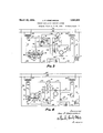
- Fig. 2 shows a slight change in the wiring connections of Fig. 1 by which this result may be accomplished.
- neutralizing coil 84 can not be energized if high limit switch 61 is open when blade 71 engages contact '75.
- the fan 13 will, therefore, remain energized until the excessive furnace temperature is reduced if the furnace temperature is excessive when blade '71 engages contact 75.
- FIG. 3 a further modification is shown whereby fan 13 is operated whenever the furnace temperature is excessive regardless of the condition of the room thermostat.
- This circuit ar- 105 rangement is to take care of thepossibility of the furnace temperature becoming excessive after the room thermostat has become satisfied as indicated by blade '71 engaging with contact 75.
- high limit switch 61A is provided with three terminals 112, 113, and 114 all of which are closed when the furnace temperature is not excessive and the high limit switch 61A is further provided with terminals 115 and 116 which are closed when the furnacetemperature becomes 115 excessive.
- the furnace temperature is such that fan switch 65 is closed, and high limit switch 61A is positioned so as to close terminals 112, 113, 114 and 120 element 18 is in engagement with contact 19 showing that pilot 17 is burning.
- the control system of Fig. 3 works exactly the same as the control system of Fig. 1 except that if the furnace temperature should become excessive while the room. thermostat is satisfied and blade '71 is in engagement with contact 75, fan 13 is operated to reduce the furnace temperature. Under such conditions high limit switch 61A would move to a position wherein terminals 115 and 116 would be connected.
- Coil '76 would then be energized as follows: secondary 89, 91, 117, 118, 115, 116, 119, 120, coil '76, and 95 to 89. Energization ofcoil '76 moves switch arms '78, '79, and 80 into engagement with their respective contacts 81, 82, and 83 to establish a holding circuit for coil '76 and to operate fan 18 as above described.
- Fig. 4 is a circuit arrangement which operates exactly in the same manner as the circuit of Fig. 1, but the relay unit operates a single switch arm 129 which engages a contact 130 that controls both the holding circuit for coil 76 and conditions the circuit for coil 84 for energization upon engagement of blade 71 with contact 75.
- switch arm 129 and contact 130 replaces switch arms 79 and 80 and contacts 82 and 83 of Fig. 1 by the use of a slightly different wiring arrangement.
- coil 76 When blade 71 engages contact 73 coil 76 is energized as follows: 89, wire 121, wire 94, contact 45, arm 43, wire 93, contact 73, blade 71, element 70, wire 122, wire 123, coil 76, and to secondary 89. Energization of 76 causes switch arm 79 to engage contact 81 and switch arm 129 to engage contact 130. Fan motor 12 is thus energized in the same manner as in Fig. 1 and a holding circuit for coil 76 is established as follows: secondary 89, wires 121, 124, contact 130, switch arm 129, wire 123, coil 76, and 95 to 89. When blade 72 engages contact 74, field 20 is energized as in Fig.
- transformer 87-89 in commercial practice is built into the relay unit which includes coils 76 and 84.
- transformer 8'7 and 89 In order to use transformer 8'7 and 89 to operate the whole circuit it would be necessary to increase its size thereby requiring a special relay which could not readily be obtained on the market.
- transformer 8890 is transmitted with the valve mechanism and the same objection to increasing the size of this transformer to eliminate the other transformer holds good.
- a system of the class described comprising, in combination, a heat increasing means, a circulation controlling device for controlling the circulation of the fluid heated bythe heat increasing means, a thermostat responsive to the temperature of the space to be heated, connections between the spacetemperature-responsive thermostat and the circulation controlling device for causing circulation of the heated fluid to the space to be heated when the temperature thereof falls to a predetermined point, thermostatically conwhich is higher than the aforesaid minimum temperature.
- a system of the class described comprising, in combination, an electrical device for controlling the circulation of a fluid, a switch in circuit therewith, a thermostat responsive to the temperature of the space to be heated for closing said switch to operate said device when the temperature of the space to be heated falls to a predetermined point, thermostatically controlled means responsive to the temperature of the fluid for preventing circulation of the fluid if the temperature thereof is below a predetermined minimum, an electrically operated heat increasing means for heating the fluid to be circulated, a space-temperature-responsive switch in circuit therewith and moved to closed position for supplying heat to the fluid upon a further fall in the temperature of the space to be heated, and means responsive to the temperature of the fluid for preventing operation of the heat increasing means if the fluid is above a predetermined maximum temperature which is higher than the aforesaid minimum temperature.
- a system of the class described comprising, in combination, a heat increasing means, a circulation controlling device for the fluid heated by the heat increasing means, a room thermostat, connections between the room thermostat and circulation controlling device for operating the same to cause circulation of fluid upon a first fall in room temperature, connections between the room thermostat and the heat increasing means for operating the same to supply heat to the fluid upon a further fall in room temperature, and thermostatic means responsive to the heated fluid for preventing operation of the heat increasing means to supply heat to the fluid when the temperature thereof is above a predetermined maximum.
- a system of the class described comprising, in combination, a heat increasing means, a circulation controlling device for the fluid heated by the heat increasing means, connections between the room thermostat and the circulation controlling device for operating the same to causecirculation of fluid upon a lowering of the room temperature to a flrst value and for preventing circulation when the room temperature rises a predetermined amount above said first value, connections between the room thermostat and the heat increasing means for operating the same to supply heat to the fluid upon a further fall in room temperature to a second value lower than the first value and for stopping such operation when the room temperature rises a predetermined amount above the second value, and means responsive to the temperature of the heated fluid for preventing operation of the heat increasing means when the temperature of the fluid is above a predetermined maximum.
- 8T Xoiitrol system for a hot air furnace incluiii ri gfin electrically operated heat increasing mean and an electrical blower device for circula gthe heated air thereby, comprising, a raw thermostat, switching mechanism operated thereby for controlling said means to produce heat'i'and for controlling said blower device to circulate the heated air when the room tem- ,-periature falls, a thermostat in the path of the heated air, and switching mechanism operated by said last named thermostat for operating said blower device if the temperature of the heated air rises above a predetermined maximum after the room temperature has been restored.
- a control system for a forced circulation hot air furnace including an electrically operated heat increasing means and an electrical blower for circulating the heated air, comprising, a room thermostat, switching mechanism operated thereby for starting the air blower when the room temperature falls to a first value, for operating said heat increasing means to supply heat to the circulating air when the room temperature falls to a second value, and for discontinuing operation of the air blower and heat increasing means when the room temperature has been restored, a thermostat responsive to furnace temperature, and switching mechanism controlled by said furnace-temperature-thermostat for operating the air blower upon eircessive furnace temperatures when the room temperature has been restored.
- a system of the class described comprising, in combination, an electrically operated heat increasing means biased to one position and movable to another position against its bias when energized, an electrical circulation controlling device for controlling the circulation of fluid heated by the heat increasing means, switching mechanism operated by said heat increasing means, thermostatically controlled switching mechanism responsive to the temperature of the space to be heated, a relay means, a switch operated thereby, an energizing circuit for the circulation controlling device controlled by the relay switch, a circuit for energizing the relay means to move the relay switch to closed circuit position on a fall in temperature of the space to be heated including the thermostatically controlled switching mechanism and-the heat increasing means operated switching mechanism and a circuit for energizing the heat increasing means to produce heat upon a further fall in the temperature of the space to be heated controlled by the thermostatically controlled switching mechanism.
- a system of the class described comprising, in combination, an electrically operated heat increasing means, an electrical circulation controlling device for controlling the circulation of fluid heated by the heat increasing means, switching mechanism in control of said device, relay means for operating said switching mechanism, a circuit changer operated by the heat increasing means, a room thermostat, an energizing circuit for the relay means including the room thermostat and heat increasing means circuit changer, a fluid temperature operated switching means, an energizing circuit for the circulation controlling device including the relay 115,
- a system of the class described comprising, in combination, a room thermostat, first and second contacts sequentially engageable thereby on temperature fall, a third contact engageable thereby on temperature rise after the first and second contacts have been disengaged, an electrical heat increasing means biased to one position and electrically operable for movement to a second position, a circuit changer controlled by the heat increasing means, relay means, an energizing circuit for the relay means including the room thermostat, its first contact and the heat increasing means circuit changer, a plurality of switches controlled by the relay means, a holding circuit for the relay means including one of the relay means controlled switches, an energizing circuit for the heat increasing means including the room thermostat and its second contact, a holding circuit for the heat increasing means including the room thermostat, its first 140 contact and the heat increasing means circuit changer, and means for operating the relay means for causing the same to assume its first position including the room thermostat, its third contact and one of the relay means controlled switches.
- a room thermostat in combination, a room thermostat, first and second contacts sequentially engageable thereby on temperature fall, a third contact engageable thereby on temperature rise after the first and second contacts have been disengaged, an electrical heat increasing means biased to one position and electrically operable for movement to a second position, a circuit changer controlled by the heat increasing means, relay means including first and second coils, an energizing circuit for one of said relay coils including the room thermostat, its first contact and the heat increasing means circuit changer, a plurality of switches moved to closed position on energization of said relay coil, a holding circuit for said relay coil including one oi said relay switches, an electrically operated fan, a fan switch, an energizing circuit for the tan including the fan switch and another oi the relay switches, a high limit switch, an energizing circuit for the heat increasing means including the room thermostat, its second contact and the high limit switch, a holding circuit for the heat increasing means including the room thermostat, its first contact, the high limit switch and the heat increasing means
- a system of the class described comprising, in combination, a room thermostat, first and second contacts engageable thereby on temperature (all. a third contact engageable thereby on temperature rise after the first and second contacts have been disengaged, anelectric fiuid control valve normally biased to cloud position, a circuit changer operable by the valve on opening and closing thereof, relay means including first and second relay'colls, an energizing circuit tor the first relay coil including the mom thermostat, its first contact and the, valve operated circuit changer, first, second and third switches moved to closed position upon energisation oi the first relay coil, a holding circuit for the firstrelay coilincludingthefirstrela'yoperatedswitchan electrical blower, a circuit for the blower includingthesecondrelayswitchanenergizingcirouit tor the valve including the room thermostat and its second contact, a holding circuit for the valve including the room thermostat, its first contact and the valve operatedcircuit changer, andan energizing circuit for the second relay coil (or moving the relay switches to open position including
- circuit changer a plurality of switches moved to a closed position upon energization of the first relay coil, a holding circuit for the first relay coil including one of the relay operated switches, an
- energ'izing circuit for the heat increasing means including the room thermostat, its second contact and the high limit switch, a holding circuit for the heat increasing means including the room thermostat, its first contact, the heat increasing means circuit changer and the high limit switch,
- the relay operated switches including the room thermostat, its third contact, the high limit switch and one of the relay operated switches whereby the relay switches will remain closed it the high limit switch is open when the room thermostat engages its third contact.
- a system of the class described comprising, in combination, a room thermostat, first and second contacts engageable thereby on temperacoils, a first source of power, an energizing circuitior the first relay coil including the room thermostat, its first contact the first source of power and the heat increasing means controlled circuit changer, an electrical circulation controlling device, a plurality of switches moved to closed position by said first relay coil when energized, a second source of power, an ena holding circuit for the heat increasing means including the room' thermostat its first contact, the third source of power and the heat increasin means controlled circuit changer. and an energizing'circuittorthesccondrelay coilioropeningthe relay operated switches including the first source or power, the room thermostat, its third contact andoneoitherelayope tedswitches.
- a circuit changer controlled by the heat increasing means a relay means comprising first and second relay coils, a first source of power, an energizing circuit for the first relay coil including the room thermostat, its first contact the first source of power and the heat increasing means controlled circuit changer, an electrical tan, a fan switch, a plurality of switches moved to closed position by said first relay coil, 8.
- an energizing circuit for the tan including the second source 01 power, fan switch, and one o! the relay operated switches, a third source of power, a high limit switch, an energizing circuit for the heat increasing means including the third source of power, high limit switch, room thermostat and its second contact, a holding circuit for the heat increasing means including the third source of power, high limit switch, room thermostat, its first contact and the heat increasing means controlled circuit'changer, and a circuit for the second relay coil for causing opening oi the relay switches including the first source of power, the room thermostat, its third contact and one of the relay operated switches.
- a systemof the class described comprising, in combination, a room thermostat, first and second contacts engageable thereby on temperature fall, a third contact engageable thereby on temperature rise after the first and second contacts have been disengaged, an electrical heat increasing means, biased to one position and electrically operable to a second position, a circuit changer controlled by the heat increasing means, a relay means comprising first and second relay coils, a source of power comprising high voltage supply lines, a first step-down transformer connected to the supply lines and having only sumcient capacity to operate the relay means, a circuit for the first relay coil including the first step-down transformer, the room thermostat, its first contact andthe heat increasing means controlled circuit changer, a plurality of switches moved to closed position by the first relay coil when energized, an electrical circulation controlling device, a circuit therefore including the supply lines and one of the relay operated switches, a second step-down transformer having only sufiicient capacity to operate the heat increasing means and connected tothe supply lines, an energizing circuit for the heat increasing means including the second stepdown
- a system of the class described comprising, in combination, a room thermostat, first and second contacts engageable thereby on temperature fall, a third contact engageable thereby on temperature rise after the first and second contacts have been disengaged, an electrical heat increasing means, biased to one position and electrically operable to a second position, a circuit changer controlled by the heat increasing means, a.
- relay means comprising first and second relay coils, a source of power comprising high voltage supply lines, a first step-down transformer connected to the supply lines and having only sufllcient capacity to operate the relay means, a circuit for the first relay coil including the first step-down transformer, the room thermostat, its first contact and the heat increasing means controlled circuit changer, first and second switches moved to closed position by the first relay coil when energized, a holding circuit for the first relay including the first step-down transformer and the first relay operated switch, an
- electrical circulation controlling device a circuit therefor including the supply lines and the second relay operated switch, a second stepdown transformer having only sufiicient capacity.to operate the heat increasing means, an energizing circuit for the heat increasing means including the second step-down transformer, room thermostat, and its second contact, a, holding circuit for the heat increasing means including the second step-down transformer, the room thermostat, its first contact and the heat increasing means controlled circuit changer, and a circuit for the second relay coil for causing opening of the relay switches including the first stepdown transformer, the room thermostat, its third contact and the first relay operated switch.
- a system of the class described comprising, a circulation controlling device for fiuid to be heated, a room thermostat, means responsive to the temperature of the fluid, connections between the circulation controlling device, room thermostat and fluid-temperature-responsive means for operating the fluid circulation controlling device upon a first fall in room temperature if the temperature of the fluid is sufficiently high, a pilot light.
- a pilot thermostat a second means responsive to fluid temperature, a. heat increasing means for heating the fluid, and connections between the heat increasing means, room thermostat, pilot thermostat and second fluid-temperature-responsive means for operating the heat increasing means upon a further fall in room temperature if the pilot is lighted and the fluid temperature is not excessive.
- a system of the class described comprising, in combination, a circulator for circulating a. fluid medium, a main control for operating said circulator in response to changes in the condition to which said main control responds, a heater for changing the heat value of said fluid medium, and means responsive to the heat value of said fluid medium for operating said circulator when the heat value of said fluid medium is too high.
- a system of the class described comprising, in combination, a circulator for circulating a fluid medium, a main control for operating said circulator in response to changes in the condition to which said main control responds, a heater for changing the heat value of said fluid medium, and means responsive to the heat value of said fluid medium for preventing operation of said circulator by the main control if the heat value of said fluid medium is too low and for operating said circulator irrespective of the main control if the heat value of the fluid medium is too high.
- a heater for heating a fluid medium electrically operated means for controlling the circulation of said fluid medium, a main control switch in control of said electrically operated means for operating the latter in accordance with changes in the condition to which said main control switch responds, and switching means responsive to the heat content of said fluid medium and associated with said main control switch and electrically operated means for preventing operation of the latter by the main control switch when the heat content of the fluid medium is too low and for operating the same irrespective of the value of the condition to which said main control switch responds when the heat content of the fluid medium is too high.
- a system of the class described comprising, in combination, a. heat increasing means, a circulation controlling device ion the fluid heated by the heat increasing means, a thermostat subject to the temperature of the space to be heated, connections between the space temperature thermostat and circulation controlling device for causing the circulation of fluid upon a fall in the space temperature and for preventing such circulation of fluid when the space temperature has been restored, means responsive to the temperature of the circulating fluid for continuing circulation of the fluid after the space temperature has been restored if the temperature of the fluid is above a predetermined maximum and means responsive to the temperature of the circulating fluid for terminating operation of the heat increasing means if the temperature of the fluid becomes too high.
- a system of the class described comprising, in combination, an electrically operated heat increasing means, an electrical circulation controlling device for the fluid heated by the heat increasing means, a circuit closing thermostat subject to the temperature of the space tobe heated, connections between the space temperature thermostat and circulation controlling device for operating the latter when the space temperature falls to a predetermined minimum and for terminating operation of the circulation controlling device when thespace temperaturehas been re-;
- thermostatic switching means responlating fluid reaches a predetermined maximum irrespective of the temperature oi! the space to 'be heated.
Landscapes
- Engineering & Computer Science (AREA)
- Physics & Mathematics (AREA)
- General Physics & Mathematics (AREA)
- Automation & Control Theory (AREA)
- Remote Sensing (AREA)
- Chemical & Material Sciences (AREA)
- Combustion & Propulsion (AREA)
- Mechanical Engineering (AREA)
- General Engineering & Computer Science (AREA)
- Control Of Combustion (AREA)
Description
March 20, 1934. J. P. KRIECHBAUM FORCED CIRCULATION HEATING SYSTEM Criginal Filed April 20, 1932 3 Sheets-Sheet 1 March 20, 1934. J. P. KRIECHBALIM 1,951,663
FORCED CIRCULATION HEATING SYSTEM Original Filed April 20, 1932 3 Sheets-Sheet 2 Fla. 6
lyrroxwrxs March J. P. KRIECHBAUM 1,951,663
FORCED CIRCULATION HEATING SYSTEM Original Filed April 20, 1932 3 Sheets-Sheet 3 MAN /r ramvz a Patented Mar. 20, 1934 FORCED CIRCULATION HEATING SYSTEM John P. Kriechbaum, Minneapolis, Minn, as-
signor to Minneapolis-Honeywell Regulator Company, Minneapolis, M'inn., a corporation of Delaware Application April 20, 1932, Serial No. 606,409
Renewed August 30, 1933 25 Claims.
The present invention relates to the type of heating system wherein the heat increasing 'means heats a fluid the circulation of which is controlled by a circulation controlling device. The
.invention relates particularly to the control of 4 forced circulation hot air furnaces wherein the heated air is circulated by means of a blower device or fan.
One of the primary objects of the invention is the provision of a control system for a forced circulation hot air furnace whereby upon a fall in room temperature the heat increasing means will be operated to supply heat to the air and the blower device will be operated to circulate the heated air to the room or space to be heated including provision for maintaining the operation of theblower device after the room temperature has been restored to normal if the air at the furnace is above a predetermined maximum temperature. Provision is also made to prevent operation of the blower device if the temperature of the circulated air is below a predetermined minimum temperature even though the space to be heated is at a temperature below that desired.
A further object of the invention is to provide a control system for a forced circulation hot air furnace in which the blower device is operated to circulate heated air to the space to be heated when the temperature of the circulated air is sufliciently high upon a first fall in temperature in the space to be heated, to operate the heat increasing means for supplying heat to the circulated air upon a further drop in room temperature provided the temperature of the circulated air is not above .or does not rise above a predetermined maximum, to stop operation of the heat increasing means when the temperature of the space to be heated has been partially restored, and to subsequently stop operation of the blower device when the temperature of the space to be heated has been fully restored.
A further object of the invention is to provide control systems such as outlined above which are relatively simple and are composed of standard apparatus that is available on the market.
Further objects of the invention will become tain modifications which m be made in the control system of Fig. 1:
Fig. 3 is a schematic wiring diagram showing a further type of control system which may be applied to the mechanism of Fig. 1;
Fig. 4 is a schematic showing of a control system similar to the system of Fig. 1, but in which a slightly difierent type of relay unit is utilized;
Fig. 5 is a detail of one of the devices diagrammatically shown in Fig. 1; and
Fig. 6 is a view showing details of the furnace switch of Pig. 1.
Referring to Fig. 1 a conventional type of hot air furnace indicated at 10 is provided with a cold air or recirculating air inlet indicated at 11. A motor 12 placed in the inlet 11 drives a fan 13 for circulating air through the furnace and into the space to be heated. The heat in: creasing means is herein shown as a burner 1-1 which is supplied with gas or other suitable combustible fluid by supply pipe 15 which in turn is controlled by a valve 16. The burner 14 is preferably supplied with a constantly burning pilotlight indicated at 17. The pilot 17 preferably heats a bimetallic element 18 which when hot engages a contact 19 whereby operation of the system is prevented in the event that the pilot goes out as will hereinafter be explained.-
Valve 16 is operated by an electric motor herein diagrammatically illustrated as being of the induction type as shown by the field coil 20 and rotor 21. Rotor 21 drives a gear 22 mounted upon a shaft 23 through reduction gearing generally indicated'at 24. Gear 22 carries a pin 25 near its periphery which pin is adapted to engage the hooked end portion 26 of a rod 27 upon rotation of gear 22 in a clockwise direction. The lower end of rod 2'! is pivotally secured to a lever 28 which in turn is pivoted as shown at 29. Valve stem 30 of valve 16 passes through lever 28 and 95 is provided with an enlarged head 31 which is held biased in engagement with lever 28 by p ing 32.
When field coil 20 is energized gear 22 is rotated clockwiseby means of rotor 21 and reduction gearing 24 whereupon pin 25 engages book 26 of rod 2'! which in turn lifts lever 28 and valve stem 30 against the bias of spring 32 to open valve 16 and allow flow of gas to burner 14. When 5 field coil 20 is deenergized spring 32 closes valve 10 16, moves lever 28 and rod 27 downwardly, and .rotates gear 22 and rotor 21 in the reverse direction until the parts are brought back to their original position as shown in Fig. 1. no
..Refen'ingtoFig.5itwillbeseenthatshaft 23 carries a cam member 33 upon each side of which is positioned a friction washer 34. One of the friction washers 34 abuts a collar 35 on shaft 23 and the other friction washer 34 is engaged by one end of a coil spring 36 wound about shaft 23 and the other end of coil spring 36 presses against a washer 37, which is held in position on shaft 23 by cotter pin 38. The motion of cam member 33 is limited to a rather narrow range by a stationary pin 39 which cooperates with the edges of a recessed portion 40 formed in cam member 33. Cam member 33 is provided with a shoulder 41 upon which a cam follower 42 is adapted to ride when cam member 33 is rotated in a clockwise direction.
Cam follower 42 is secured to a lever 43 pivoted at 44 which is normally biased into engagement with a contact 45 by means of tension spring 46. When follower 42, however, rides up shoulder 41 contact arm '43 disengages contact 45 and ensages a contact 47.
It will be noted that by reason of the frictional connection of shaft 23 and cam member 33 taken together with stop pin 39 and the recessed portion 40, cam member 33 will be moved to cause contact arm 43 to disengage contact 45 and engage contact 47 upon initial movement of gear 22 in a clockwise direction and after this. circuit change has taken place, shaft 23 will continue rotating and cam member 33 will remain stationary. Likewise, the reverse action takes place causing contact arm 43 to disengage contact 47 and engage contact 45 upon initial movement of gear 22 in counter-clockwise direction. The control system includes a thermostatic switch (see Figs. 1 and 6) which comprises a casing 48 provided with a lateraltubular extension 49 which terminates within the bonnet of furnace 10. An. helically coiled bimetallic element 50 has one of its ends secured to extension 49 and has its other end secured to a rod 51 which extends through tubular extension 49 and terminates within casing 48. It will be obvious that bimetallic element 50 responds to the temrature of the air within the bonnet of furnace 0. Shaft 51 carries three cams 52, 53, and 54 which are adiustably secured to the shaft 51 by thumb nut 55. A bracket 56 is pivoted to casing 48 as shown at 57 and is provided with a down ward extension 58 which carries a roller 59. Bracket 56 is also provided with upwardly extending clips 60 which carry a mercury switch 61 which will be hereinafter referred. to as the high limit switch". It will be seen that pivot 57 is removed from the center of bracket 56 so that the weight of bracket 56 and high limit switch 61 always maintains roller 59 in contact with the periphery of cam 52. The cam 52 is provided with the shoulder 62 so that upon rotation of cam 52 in a counter-clockwise direction as a result of excessive temperature in the furnace 10, high limit switch 61 will be'allowed to rotate in a clockwise direction about its pivot 57 to open circuit posiiton. A bracket 63 which is pivoted to casing 48 as shown at 64 supports a mercury switch 65 which will hereinafter be referred to as the "fan switch". Bracket 63 is provided with upwardly extending arms 66 and 67 the former of which is adapted to be engaged by a shoulder 68 on cam 53 upon temperature riseand the latter of which is adapted to be engaged by a shoulder 69 on cam 54 on a temperature fall at bimetallic e1ement50. Inasmuchasfanswitch 65hasits centraiportionsecuredtobmcket63.thisassembly will remain in either open or closed'position after having been moved thereto by shoulder 69 or shoulder 68. After having been moved to either open or closed position bracket 63 and fan switch 65 are prevented from rotating an undue amount by engagement of arm 66 or 67 as the case may be with the periphery of cam 53 or 54.
The control system also includes a room thermostat comprising a bimetallic volute 70 to the free end of which are secured flexible contact blades 71 and 72. On a lowering of room temperature flexible blade '11 first engages the contact 73' and subsequently flexible blade 72 engages contact 74. When the room temperature rises flexible blade 72 first leaves contact 74, flexible blade 71 subsequently leaves contact 73 and when the room temperature has been restored to normal flexible blade 71 engages a contact 75.
The control system also includes a standard relay means of the double coil type. Coil 76 upon energization attracts armature 77 which in turn moves switch arms 78, 79, and 80 into engagement with contacts 81, 82, and 83. A bucking coil 84 when energized neutralizes the magnetic effect of coil 76 thereby allowing armature 77 to move to the position of Fig. 1 under the action of gravity.
the fan switch 65 would be in open circuit position and fan motor 12 would not be energized.
Assuming that there was not sufllcient heat in furnace 10 to prevent further fall in room temperature, contact blade 72 will engage contact 74 to establish an energizing circuit for fleld .20 as follows: secondary 90, wire 102, element 18, contact 19, wire 103, high limit switch 61, wire 104, element 70, blade 72, contact 74, wire 105, wire 106, field 20, and wire 107 to secondary 90. It will be seen that this energizing circuit for field 20 includes element 18 and contact 19 so that valve 16 can not be opened if pilot 17 is extinguished. Energization of field 20 opens valve 16 as hereinbefore described and gas is supplied to burner 14 and ignited by pilot 1'7.
Opening of valve 16 also moves contact arm 43 from engagement with contact 45 and into engagement with contact 4'7.
Engagement of contact arm 43 with contact 4'! establishes a holding circuit for field 20 which is as follows: secondary 90, 102, 18, 19, '103, 61, 104, '70, blade '71, contact '73, wire 93, contact arm 43, contact 47, wire 108, 106, field 20, and 107 to secondary 90. It will be seen that energization of field 20 is accomplished by engagement of blade '72 with contact '74, but that field 20 is maintained energized by the holding circuit just described until blade '71 leaves contact '73.
It will be obvious that if high limit switch 61 is in open position because of excess bonnet temperatures in the furnace 10, field coil 20 cannot be energized or will be deenergized subsequent to energization if high limit switch 61 should open after field 20 has been energized.
Since heat is being supplied by burner 14 and this heat is being circulated to the room by fan 13, the room temperature will begin to rise.
When blade '72 leaves contact '74 there will be no change in the system because of the holding circuit for field 20, but when the room temperature has risen sufficiently to cause blade '71 to leave contact '73 the field 20 will be deenergized and valve 16 will move to closed position under the bias of spring 32 thereby cutting off the supply of fuel to burner 14. The closing of valve 16 also rotates cam member 33 in counter-clockwise direction permitting spring 46 to move contact arm 43 from engagement with contact 4'7 and into engagement with contact 45 as above described. Fan 13 is still being operated and will deliver the heat remaining in furnace 10 into the room. If this heat is sutlicient to cause element '70 to move blade '71 into engagement with contact '75, an energizing circuit for relay coil 84 will be established asfollows: secondary 89,
91, 92, '70, blade '71, contact 75, wire 109, contact 82, switch arm '79, wire 110, coil 84, and wire 95 back to secondary 89. Coil 84 when energized creates a magnetic fiux equal and opposite to the magnetic flux created by coil '76. The effective magnetism on armature '77 is zero so that armature '77 and its associated switch arms '78, '79, and 80 will move to the position of Fig. 1 under the influence of gravity bringing the system back to its original condition.
From the foregoing description of Fig. 1 it will be observed that on a first fall in temperature the fan 13 is operated to remove any heat from furnace 10 that might be present. If this heat is sufilcient to restore the room temperature so that blade '71 engages contact '75, fan 13 will cease operating. If there is no heat in the furnace, operation of fan 13 is prevented by means of fan switch 65. If there is no heat in the furnace so that fan 18 can not be operated or if the heat present in the furnace is not sufllcient to prevent a further fall in room temperature, blade '72 engages contact '74 and valve 16 is opened to supply fuel to burner 14 provided pilot 17 is not extinguished. Valve 16 will remain open until the room temperature has been partially restored so as to cause blade '71 to leave contact '73 provided the furnace temperature is not or does not become excessive in which case high limit switch 61 will cause closure of valve 16. When the room temperature has been fully re stored engagement of blade '71 with contact '75 causes a complete shut down of the system. v
It is conceivable that with certain types of furnaces and with certain types of heat-increasing means the furnace temperature may become excessive after the heat-increasing means has been operated to decrease the supply of heatto the furnace as indicated by blade '71 leaving contact 73 and before the room thermostat becomesfully satisfied as indicated by blade '71 engaging contact '75. Under such conditions it may be desirable to continue fan operation even after the room temperature has been restored. Fig. 2 shows a slight change in the wiring connections of Fig. 1 by which this result may be accomplished. The initial energizing circuit for coil '76 and the energizing circuit for coil 84 after leaving wire 91, go by way of a wire 111 to high limit switch 61 and then through wire 104 to element '70. By this arrangement neutralizing coil 84 can not be energized if high limit switch 61 is open when blade 71 engages contact '75. The fan 13 will, therefore, remain energized until the excessive furnace temperature is reduced if the furnace temperature is excessive when blade '71 engages contact 75.
In Fig. 3 a further modification is shown whereby fan 13 is operated whenever the furnace temperature is excessive regardless of the condition of the room thermostat. ,This circuit ar- 105 rangement is to take care of thepossibility of the furnace temperature becoming excessive after the room thermostat has become satisfied as indicated by blade '71 engaging with contact 75.
In this figure high limit switch 61A is provided with three terminals 112, 113, and 114 all of which are closed when the furnace temperature is not excessive and the high limit switch 61A is further provided with terminals 115 and 116 which are closed when the furnacetemperature becomes 115 excessive.
With the parts as shown the room is cooling, the furnace temperature is such that fan switch 65 is closed, and high limit switch 61A is positioned so as to close terminals 112, 113, 114 and 120 element 18 is in engagement with contact 19 showing that pilot 17 is burning. The control system of Fig. 3 works exactly the same as the control system of Fig. 1 except that if the furnace temperature should become excessive while the room. thermostat is satisfied and blade '71 is in engagement with contact 75, fan 13 is operated to reduce the furnace temperature. Under such conditions high limit switch 61A would move to a position wherein terminals 115 and 116 would be connected. Coil '76 would then be energized as follows: secondary 89, 91, 117, 118, 115, 116, 119, 120, coil '76, and 95 to 89. Energization ofcoil '76 moves switch arms '78, '79, and 80 into engagement with their respective contacts 81, 82, and 83 to establish a holding circuit for coil '76 and to operate fan 18 as above described.
When the excess heat has been removed from the furnace, high limit switch 61A will move to 40 the position shown in Fig. 3 whereupon neutralizing coil 84 will be energized as follows: secondary 89, 91, 117, 114, 113, 104, '70, '71, '75, 109, 82, '79, 110, 84, and 95 to 89. It will be apparent then that the arrangement of Fig. 3 gives the two-stage control of Fig. 1 plus the added feature of operating fan 13 upon excessive furnace temperature even though the room is at normal temperature. This is an added safeguard which prevents over-heating of the furnace even at the expense of a slight over-heating in the room.
Fig. 4 is a circuit arrangement which operates exactly in the same manner as the circuit of Fig. 1, but the relay unit operates a single switch arm 129 which engages a contact 130 that controls both the holding circuit for coil 76 and conditions the circuit for coil 84 for energization upon engagement of blade 71 with contact 75. In other words, switch arm 129 and contact 130 replaces switch arms 79 and 80 and contacts 82 and 83 of Fig. 1 by the use of a slightly different wiring arrangement.
When blade 71 engages contact 73 coil 76 is energized as follows: 89, wire 121, wire 94, contact 45, arm 43, wire 93, contact 73, blade 71, element 70, wire 122, wire 123, coil 76, and to secondary 89. Energization of 76 causes switch arm 79 to engage contact 81 and switch arm 129 to engage contact 130. Fan motor 12 is thus energized in the same manner as in Fig. 1 and a holding circuit for coil 76 is established as follows: secondary 89, wires 121, 124, contact 130, switch arm 129, wire 123, coil 76, and 95 to 89. When blade 72 engages contact 74, field 20 is energized as in Fig. 1, and the subsequent engagement of contact arm 43 with contact 47 establishes a holding circuit forfleld 20 as in Fig. 1. When the room temperature has been restored so that blade 71 engages contact 75 an energizing circuit for coil 84 is established as follows: secondary 89, wires 121*, 124, contact 130, switch arm 129, wire 122, element 70, blade 71, contact 75, wire 125, coil 84, and wire 95 to 89.
The arrangement of Fig. 4, therefore, eliminates one of the switches of the circuit of Fig. 1. It is to be understood that this same rearrangement could be made in Figs. 2 and 3.
While the fan switch 65 and high limit switch 61 have been shown as mercury switches and the remaining switching mechanisms have been shown as open contacts, it is to be understood that either mercury switches or open contacts could be used throughout the circuit arrangements of Figs. 1 to 4 inclusive.
It should be noted that while two transformers have been shown in these various circuits a single transformer could be substituted if desired. Two transformers have been shown herein since the transformer 87-89 in commercial practice is built into the relay unit which includes coils 76 and 84. In order to use transformer 8'7 and 89 to operate the whole circuit it would be necessary to increase its size thereby requiring a special relay which could not readily be obtained on the market. Likewise, transformer 8890 is transmitted with the valve mechanism and the same objection to increasing the size of this transformer to eliminate the other transformer holds good.
In Figs. 1, 2, 3, and 4 similar reference characters have been used to indicate like parts and wiring connections.
I claim as my invention:
1. A system of the class described, comprising, in combination, a heat increasing means, a circulation controlling device for controlling the circulation of the fluid heated bythe heat increasing means, a thermostat responsive to the temperature of the space to be heated, connections between the spacetemperature-responsive thermostat and the circulation controlling device for causing circulation of the heated fluid to the space to be heated when the temperature thereof falls to a predetermined point, thermostatically conwhich is higher than the aforesaid minimum temperature.
2. A system of the class described, comprising, in combination, an electrical device for controlling the circulation of a fluid, a switch in circuit therewith, a thermostat responsive to the temperature of the space to be heated for closing said switch to operate said device when the temperature of the space to be heated falls to a predetermined point, thermostatically controlled means responsive to the temperature of the fluid for preventing circulation of the fluid if the temperature thereof is below a predetermined minimum, an electrically operated heat increasing means for heating the fluid to be circulated, a space-temperature-responsive switch in circuit therewith and moved to closed position for supplying heat to the fluid upon a further fall in the temperature of the space to be heated, and means responsive to the temperature of the fluid for preventing operation of the heat increasing means if the fluid is above a predetermined maximum temperature which is higher than the aforesaid minimum temperature.
3. A system of the class described, comprising, in combination, a heat increasing means, a circulation controlling device for the fluid heated by the heat increasing means, a room thermostat, connections between the room thermostat and circulation controlling device for operating the same to cause circulation of fluid upon a first fall in room temperature, connections between the room thermostat and the heat increasing means for operating the same to supply heat to the fluid upon a further fall in room temperature, and thermostatic means responsive to the heated fluid for preventing operation of the heat increasing means to supply heat to the fluid when the temperature thereof is above a predetermined maximum.
4. A system of the class described, comprising, in combination, a heat increasing means, a circulation controlling device for the fluid heated by the heat increasing means, connections between the room thermostat and the circulation controlling device for operating the same to causecirculation of fluid upon a lowering of the room temperature to a flrst value and for preventing circulation when the room temperature rises a predetermined amount above said first value, connections between the room thermostat and the heat increasing means for operating the same to supply heat to the fluid upon a further fall in room temperature to a second value lower than the first value and for stopping such operation when the room temperature rises a predetermined amount above the second value, and means responsive to the temperature of the heated fluid for preventing operation of the heat increasing means when the temperature of the fluid is above a predetermined maximum.
5. A system of the class described, comprising, in combination, a heat increasing means, a ciro ri temperature has ure of the fluid is um. described, compris- "at increasing means, evice for the fluid ea' t iincreasing means, a room :jfthe temperature of the h tween the room thermostat gul i3 c trolling device and heat using circulation of fluid upon fall in room temperare ntirig such circulation of fluid tre when the room temperature b 'd fiiild means responsive to the go fthi tjirculating fluid for operatc iilatigigi fcontrolling device to cause olffi'iji" -if the temperature thereof iisegf jfiw m; iid'etermmed maximum after the 31;; refs, re has been restored. 7f? for a hot air furnace includini fiii ifitfltally operated heat increasing 'fi'lectrical blower device for cirtli ali, heated thereby, comprising, a :igiiii fitit, switching mechanism operated the oiitrolling said means to produce hea Ffcontrolling said blower device to ,c;i rculaltgthefil ieated' air when the room tempera- ""tlire fti f a filiermostat in the path of the heated air,"' I, itching mechanism operated by said lasFhweithermostat for continuing operation of bfitver device after the room temperature alias:bfit'ffiestored if the temperature of the "'lieait'fifiaif' is above a predetermined maximum;
8T Xoiitrol system for a hot air furnace incluiii ri gfin electrically operated heat increasing mean and an electrical blower device for circula gthe heated air thereby, comprising, a raw thermostat, switching mechanism operated thereby for controlling said means to produce heat'i'and for controlling said blower device to circulate the heated air when the room tem- ,-periature falls, a thermostat in the path of the heated air, and switching mechanism operated by said last named thermostat for operating said blower device if the temperature of the heated air rises above a predetermined maximum after the room temperature has been restored.
9. A control system for a forced circulation hot air furnace including an electrically operated heat increasing means and an electrical blower for circulating the heated air, comprising, a room thermostat, switching mechanism operated thereby for starting the air blower when the room temperature falls to a first value, for operating said heat increasing means to supply heat to the circulating air when the room temperature falls to a second value, and for discontinuing operation of the air blower and heat increasing means when the room temperature has been restored, a thermostat responsive to furnace temperature, and switching mechanism controlled by said furnace-temperature-thermostat for operating the air blower upon eircessive furnace temperatures when the room temperature has been restored.
10. A system of the class described, comprising, in combination, an electrically operated heat increasing means biased to one position and movable to another position against its bias when energized, an electrical circulation controlling device for controlling the circulation of fluid heated by the heat increasing means, switching mechanism operated by said heat increasing means, thermostatically controlled switching mechanism responsive to the temperature of the space to be heated, a relay means, a switch operated thereby, an energizing circuit for the circulation controlling device controlled by the relay switch, a circuit for energizing the relay means to move the relay switch to closed circuit position on a fall in temperature of the space to be heated including the thermostatically controlled switching mechanism and-the heat increasing means operated switching mechanism and a circuit for energizing the heat increasing means to produce heat upon a further fall in the temperature of the space to be heated controlled by the thermostatically controlled switching mechanism.
11. A system of the class described, comprising, in combination, an electrically operated heat increasing means, an electrical circulation controlling device for controlling the circulation of fluid heated by the heat increasing means, switching mechanism in control of said device, relay means for operating said switching mechanism, a circuit changer operated by the heat increasing means, a room thermostat, an energizing circuit for the relay means including the room thermostat and heat increasing means circuit changer, a fluid temperature operated switching means, an energizing circuit for the circulation controlling device including the relay 115,
means operated switching mechanism and the fluid temperature operated switching means, and an energizing circuit for the heat increasing means including the-room thermostat and the fluid temperature operated switching means.
12. A system of the class described, comprising, in combination, a room thermostat, first and second contacts sequentially engageable thereby on temperature fall, a third contact engageable thereby on temperature rise after the first and second contacts have been disengaged, an electrical heat increasing means biased to one position and electrically operable for movement to a second position, a circuit changer controlled by the heat increasing means, relay means, an energizing circuit for the relay means including the room thermostat, its first contact and the heat increasing means circuit changer, a plurality of switches controlled by the relay means, a holding circuit for the relay means including one of the relay means controlled switches, an energizing circuit for the heat increasing means including the room thermostat and its second contact, a holding circuit for the heat increasing means including the room thermostat, its first 140 contact and the heat increasing means circuit changer, and means for operating the relay means for causing the same to assume its first position including the room thermostat, its third contact and one of the relay means controlled switches. i v 7 13. A system of the class described, comprising,
in combination, a room thermostat, first and second contacts sequentially engageable thereby on temperature fall, a third contact engageable thereby on temperature rise after the first and second contacts have been disengaged, an electrical heat increasing means biased to one position and electrically operable for movement to a second position, a circuit changer controlled by the heat increasing means, relay means including first and second coils, an energizing circuit for one of said relay coils including the room thermostat, its first contact and the heat increasing means circuit changer, a plurality of switches moved to closed position on energization of said relay coil, a holding circuit for said relay coil including one oi said relay switches, an electrically operated fan, a fan switch, an energizing circuit for the tan including the fan switch and another oi the relay switches, a high limit switch, an energizing circuit for the heat increasing means including the room thermostat, its second contact and the high limit switch, a holding circuit for the heat increasing means including the room thermostat, its first contact, the high limit switch and the heat increasing means circuit changer and an energizing circuit tor the other-relay coil for opening the relay switches including the room thermostat, and'one of the relay controlled switches.
14. A system of the class described, comprising, in combination, a room thermostat, first and second contacts engageable thereby on temperature (all. a third contact engageable thereby on temperature rise after the first and second contacts have been disengaged, anelectric fiuid control valve normally biased to cloud position, a circuit changer operable by the valve on opening and closing thereof, relay means including first and second relay'colls, an energizing circuit tor the first relay coil including the mom thermostat, its first contact and the, valve operated circuit changer, first, second and third switches moved to closed position upon energisation oi the first relay coil, a holding circuit for the firstrelay coilincludingthefirstrela'yoperatedswitchan electrical blower, a circuit for the blower includingthesecondrelayswitchanenergizingcirouit tor the valve including the room thermostat and its second contact, a holding circuit for the valve including the room thermostat, its first contact and the valve operatedcircuit changer, andan energizing circuit for the second relay coil (or moving the relay switches to open position including the room thermostat, its contact,
circuit changer, a plurality of switches moved to a closed position upon energization of the first relay coil, a holding circuit for the first relay coil including one of the relay operated switches, an
electrical blower, a circuit for the blower including another of the relay operated switches, an
energ'izing circuit for the heat increasing means including the room thermostat, its second contact and the high limit switch, a holding circuit for the heat increasing means including the room thermostat, its first contact, the heat increasing means circuit changer and the high limit switch,
and a circuit for the second relay coil for causing opening 0! the relay operated switches including the room thermostat, its third contact, the high limit switch and one of the relay operated switches whereby the relay switches will remain closed it the high limit switch is open when the room thermostat engages its third contact.
16. A system of the class described, comprising, in combination, a room thermostat, first and second contacts engageable thereby on temperacoils, a first source of power, an energizing circuitior the first relay coil including the room thermostat, its first contact the first source of power and the heat increasing means controlled circuit changer, an electrical circulation controlling device, a plurality of switches moved to closed position by said first relay coil when energized, a second source of power, an ena holding circuit for the heat increasing means including the room' thermostat its first contact, the third source of power and the heat increasin means controlled circuit changer. and an energizing'circuittorthesccondrelay coilioropeningthe relay operated switches including the first source or power, the room thermostat, its third contact andoneoitherelayope tedswitches.
17. A system 0! the 0 described, comprising, in combination, a room th ostat, first and second contacts engageable by on temperature fail, a third contact engageable thereby on temperature rise after the first, and second contacts have been disengaged, an electrical heat increas-' ing means biased to one position and elec- -trically operable to a second position. a circuit changer controlled by the heat increasing means, a relay means comprising first and second relay coils, a first source of power, an energizing circuit for the first relay coil including the room thermostat, its first contact the first source of power and the heat increasing means controlled circuit changer, an electrical tan, a fan switch, a plurality of switches moved to closed position by said first relay coil, 8. second source of power, an energizing circuit for the tan including the second source 01 power, fan switch, and one o! the relay operated switches, a third source of power, a high limit switch, an energizing circuit for the heat increasing means including the third source of power, high limit switch, room thermostat and its second contact, a holding circuit for the heat increasing means including the third source of power, high limit switch, room thermostat, its first contact and the heat increasing means controlled circuit'changer, and a circuit for the second relay coil for causing opening oi the relay switches including the first source of power, the room thermostat, its third contact and one of the relay operated switches.
18. A systemof the class described, comprising, in combination, a room thermostat, first and second contacts engageable thereby on temperature fall, a third contact engageable thereby on temperature rise after the first and second contacts have been disengaged, an electrical heat increasing means, biased to one position and electrically operable to a second position, a circuit changer controlled by the heat increasing means, a relay means comprising first and second relay coils, a source of power comprising high voltage supply lines, a first step-down transformer connected to the supply lines and having only sumcient capacity to operate the relay means, a circuit for the first relay coil including the first step-down transformer, the room thermostat, its first contact andthe heat increasing means controlled circuit changer, a plurality of switches moved to closed position by the first relay coil when energized, an electrical circulation controlling device, a circuit therefore including the supply lines and one of the relay operated switches, a second step-down transformer having only sufiicient capacity to operate the heat increasing means and connected tothe supply lines, an energizing circuit for the heat increasing means including the second stepdown transformer, the room thermostat and its second contact, a holding circuit for the heat increasing means including the second step-down transformer, the room thermostat, its first contact and the heat increasing means controlled circuit changer, and a circuit for the second relay coil for causing opening of the relay switches including the first step-down transformer, the room thermostat, its third contact and one of the relay operated switches.
19. A system of the class described, comprising, in combination, a room thermostat, first and second contacts engageable thereby on temperature fall, a third contact engageable thereby on temperature rise after the first and second contacts have been disengaged, an electrical heat increasing means, biased to one position and electrically operable to a second position, a circuit changer controlled by the heat increasing means, a. relay means comprising first and second relay coils, a source of power comprising high voltage supply lines, a first step-down transformer connected to the supply lines and having only sufllcient capacity to operate the relay means, a circuit for the first relay coil including the first step-down transformer, the room thermostat, its first contact and the heat increasing means controlled circuit changer, first and second switches moved to closed position by the first relay coil when energized, a holding circuit for the first relay including the first step-down transformer and the first relay operated switch, an
electrical circulation controlling device, a circuit therefor including the supply lines and the second relay operated switch, a second stepdown transformer having only sufiicient capacity.to operate the heat increasing means, an energizing circuit for the heat increasing means including the second step-down transformer, room thermostat, and its second contact, a, holding circuit for the heat increasing means including the second step-down transformer, the room thermostat, its first contact and the heat increasing means controlled circuit changer, and a circuit for the second relay coil for causing opening of the relay switches including the first stepdown transformer, the room thermostat, its third contact and the first relay operated switch.
20. A system of the class described comprising, a circulation controlling device for fiuid to be heated, a room thermostat, means responsive to the temperature of the fluid, connections between the circulation controlling device, room thermostat and fluid-temperature-responsive means for operating the fluid circulation controlling device upon a first fall in room temperature if the temperature of the fluid is sufficiently high, a pilot light. a pilot thermostat, a second means responsive to fluid temperature, a. heat increasing means for heating the fluid, and connections between the heat increasing means, room thermostat, pilot thermostat and second fluid-temperature-responsive means for operating the heat increasing means upon a further fall in room temperature if the pilot is lighted and the fluid temperature is not excessive.
21. A system of the class described, comprising, in combination, a circulator for circulating a. fluid medium, a main control for operating said circulator in response to changes in the condition to which said main control responds, a heater for changing the heat value of said fluid medium, and means responsive to the heat value of said fluid medium for operating said circulator when the heat value of said fluid medium is too high.
22. A system of the class described, comprising, in combination, a circulator for circulating a fluid medium, a main control for operating said circulator in response to changes in the condition to which said main control responds, a heater for changing the heat value of said fluid medium, and means responsive to the heat value of said fluid medium for preventing operation of said circulator by the main control if the heat value of said fluid medium is too low and for operating said circulator irrespective of the main control if the heat value of the fluid medium is too high.
23. In combination, a heater for heating a fluid medium, electrically operated means for controlling the circulation of said fluid medium, a main control switch in control of said electrically operated means for operating the latter in accordance with changes in the condition to which said main control switch responds, and switching means responsive to the heat content of said fluid medium and associated with said main control switch and electrically operated means for preventing operation of the latter by the main control switch when the heat content of the fluid medium is too low and for operating the same irrespective of the value of the condition to which said main control switch responds when the heat content of the fluid medium is too high.
24. A system of the class described, comprising, in combination, a. heat increasing means, a circulation controlling device ion the fluid heated by the heat increasing means, a thermostat subject to the temperature of the space to be heated, connections between the space temperature thermostat and circulation controlling device for causing the circulation of fluid upon a fall in the space temperature and for preventing such circulation of fluid when the space temperature has been restored, means responsive to the temperature of the circulating fluid for continuing circulation of the fluid after the space temperature has been restored if the temperature of the fluid is above a predetermined maximum and means responsive to the temperature of the circulating fluid for terminating operation of the heat increasing means if the temperature of the fluid becomes too high.
25. A system of the class described, comprising, in combination, an electrically operated heat increasing means, an electrical circulation controlling device for the fluid heated by the heat increasing means, a circuit closing thermostat subject to the temperature of the space tobe heated, connections between the space temperature thermostat and circulation controlling device for operating the latter when the space temperature falls to a predetermined minimum and for terminating operation of the circulation controlling device when thespace temperaturehas been re-;
stored. and thermostatic switching means responlating fluid reaches a predetermined maximum irrespective of the temperature oi! the space to 'be heated.
- JOHN P. HIECHBAUM.
' moi
Priority Applications (1)
| Application Number | Priority Date | Filing Date | Title |
|---|---|---|---|
| US606409A US1951663A (en) | 1932-04-20 | 1932-04-20 | Forced circulation heating system |
Applications Claiming Priority (1)
| Application Number | Priority Date | Filing Date | Title |
|---|---|---|---|
| US606409A US1951663A (en) | 1932-04-20 | 1932-04-20 | Forced circulation heating system |
Publications (1)
| Publication Number | Publication Date |
|---|---|
| US1951663A true US1951663A (en) | 1934-03-20 |
Family
ID=24427844
Family Applications (1)
| Application Number | Title | Priority Date | Filing Date |
|---|---|---|---|
| US606409A Expired - Lifetime US1951663A (en) | 1932-04-20 | 1932-04-20 | Forced circulation heating system |
Country Status (1)
| Country | Link |
|---|---|
| US (1) | US1951663A (en) |
Cited By (5)
| Publication number | Priority date | Publication date | Assignee | Title |
|---|---|---|---|---|
| US2751153A (en) * | 1953-06-23 | 1956-06-19 | Donald W Seifert | Warm air heating system control |
| US2801055A (en) * | 1954-06-28 | 1957-07-30 | Seifert Donald | Heating system control and thermostatically controlled switch therefor |
| US3489346A (en) * | 1968-11-14 | 1970-01-13 | Carl G Howard | Furnace emergency control |
| US3523643A (en) * | 1968-01-12 | 1970-08-11 | Robertshaw Controls Co | Temperature control system with recycling high limit |
| US4515306A (en) * | 1983-05-13 | 1985-05-07 | Grant Willie T | Four-terminal zone thermostat |
-
1932
- 1932-04-20 US US606409A patent/US1951663A/en not_active Expired - Lifetime
Cited By (5)
| Publication number | Priority date | Publication date | Assignee | Title |
|---|---|---|---|---|
| US2751153A (en) * | 1953-06-23 | 1956-06-19 | Donald W Seifert | Warm air heating system control |
| US2801055A (en) * | 1954-06-28 | 1957-07-30 | Seifert Donald | Heating system control and thermostatically controlled switch therefor |
| US3523643A (en) * | 1968-01-12 | 1970-08-11 | Robertshaw Controls Co | Temperature control system with recycling high limit |
| US3489346A (en) * | 1968-11-14 | 1970-01-13 | Carl G Howard | Furnace emergency control |
| US4515306A (en) * | 1983-05-13 | 1985-05-07 | Grant Willie T | Four-terminal zone thermostat |
Similar Documents
| Publication | Publication Date | Title |
|---|---|---|
| US2276195A (en) | Motorized valve | |
| US1997559A (en) | Automatic control system | |
| US2308555A (en) | Fuel burner system | |
| US1951663A (en) | Forced circulation heating system | |
| US2269036A (en) | Summer-winter air conditioning control system | |
| US2865610A (en) | Control apparatus | |
| US2024385A (en) | Heater-cooler thermostat | |
| US2226510A (en) | Air conditioning system | |
| US2262341A (en) | System for controlling the flow of heating mediums | |
| US2195219A (en) | Motor operated mechanism | |
| US2169696A (en) | Electrically operated heater control | |
| US3047273A (en) | Air conditioning apparatus | |
| US2039300A (en) | Control for air conditioning systems | |
| US2140473A (en) | Control system | |
| US2109862A (en) | Temperature control system | |
| US2786632A (en) | Control apparatus for forced air furnace | |
| US2169168A (en) | Damper regulator | |
| US2348143A (en) | Control for combustion apparatus | |
| US2640649A (en) | Thermostatic control apparatus for heating systems | |
| US2243753A (en) | Furnace damper control system | |
| US2353498A (en) | Valve operated motor controlling switch | |
| US2120803A (en) | Heating system | |
| US2246550A (en) | Control for conditioning systems | |
| US2086482A (en) | Control for air conditioning systems | |
| US1993262A (en) | Temperature changing system employing a circulating fluid medium |