US1940407A - Spring-engaged shoe clutch - Google Patents
Spring-engaged shoe clutch Download PDFInfo
- Publication number
- US1940407A US1940407A US540229A US54022931A US1940407A US 1940407 A US1940407 A US 1940407A US 540229 A US540229 A US 540229A US 54022931 A US54022931 A US 54022931A US 1940407 A US1940407 A US 1940407A
- Authority
- US
- United States
- Prior art keywords
- shoe
- lever
- shoes
- levers
- pivoted
- Prior art date
- Legal status (The legal status is an assumption and is not a legal conclusion. Google has not performed a legal analysis and makes no representation as to the accuracy of the status listed.)
- Expired - Lifetime
Links
- 241000239290 Araneae Species 0.000 description 10
- 230000000694 effects Effects 0.000 description 2
- 230000004048 modification Effects 0.000 description 2
- 238000012986 modification Methods 0.000 description 2
- 230000000717 retained effect Effects 0.000 description 2
- 238000004873 anchoring Methods 0.000 description 1
- 238000002485 combustion reaction Methods 0.000 description 1
- 210000005069 ears Anatomy 0.000 description 1
- 238000004519 manufacturing process Methods 0.000 description 1
- 230000003014 reinforcing effect Effects 0.000 description 1
- 238000003466 welding Methods 0.000 description 1
Images
Classifications
-
- F—MECHANICAL ENGINEERING; LIGHTING; HEATING; WEAPONS; BLASTING
- F16—ENGINEERING ELEMENTS AND UNITS; GENERAL MEASURES FOR PRODUCING AND MAINTAINING EFFECTIVE FUNCTIONING OF MACHINES OR INSTALLATIONS; THERMAL INSULATION IN GENERAL
- F16D—COUPLINGS FOR TRANSMITTING ROTATION; CLUTCHES; BRAKES
- F16D13/00—Friction clutches
- F16D13/14—Friction clutches with outwardly-movable clutching members co-operating with the inner surface of a drum or the like
- F16D13/18—Friction clutches with outwardly-movable clutching members co-operating with the inner surface of a drum or the like shaped as linked or separately-pivoted segments
Definitions
- This invention relates to friction clutches of Each lever is formed with a pair of side plates the shoe type, including those employing out-' spaced from those of the adjacent shoe body by wardly-acting shoes. Its objects areto provide. means of washers 28, and the link is held on improvements in such clutches adapting them the inner pivotpin,26between said plates, the
- Fig. 1 is a 1on'- projecting radially inward therefrom. This argitudinalsection of a clutch embodying the presrangement avoids the use of separate retaining 1o ent invention in a preferred form. means" for the pin'26.
- the outer pivot pin 27 2 is a rear elevation from the plane 24-2. may be detachably retained against endwise of Fig. 1, partly broken away and in section.
- the imassj of this block added to theweight engine, having a-flang e 11 provided with an inof the, associated parts onthe same side of the $0 ternal cylindrical friction surface. :12 is the pivot pin'16,enables the lever 24 to counter-'75 driven shaft whose forward end is supported by' balance theefiect of centrifugal force upon the anlanti friction pilot bearing 13v in the web ,of short arm of said lever and its link and the free the flywheel. end "of the shoe connected with saidlink.
- - 14 is. three-armed spider whose hub is con-.
- .1 provide 25. nected ,by splines 15 in non-turning engagement a shoeprojecting spring connecting each of the so withthe shaft 12 for supporting the friction shoes shoes. 1'7 7 with ,the arm of the" lever 24 located andtheiroperating levers.
- each wardly-engaging friction shoes 17 here shown having a hooked inner .end 34 anchored around 7 asthree in number, although the number might a, cross pin 35 which connects the side plates of 5 be varied,
- Each shoe comprises a body including the lever 24, and'a slightly curved outer end 7 an arcuate foundation plate 18 to which the fric bearing against the inner side of the foundation tion facings 19 are secured, and side plates 20 plate 18 of theshoe nearlits linked connection 7 attached to said foundation plate in a suitable with the nest lever 24 which operates said shoe. gdmanner as by spot welding.
- each of these springs Inits unstressed-condition, each of these springs straddle-the ends of the spider, arms and are is substantially straightbut isplaced under tenprovided with perforated reinforcing plates 21 sion to exert the; desired outward pressure on welded to the side plates and surrounding the the, shoe bybending it around a bearing corner pivot pins 16.
- Each pin is detachably secured in 134 of the weight block 31.
- the sleeve has a through a link 25 connected by an inner pivot pin cam shoulder for each of the roller arms 37, and 26 with the lever arm, and by an outer pivot pin extending forwardlybeyond each of said shoul- P5 2.7 with the shoe.
- a 1 3 ders is ahorizontalportionlor horn 44 projecting engage the rollers 38 to turn the levers'24 on their.
- This clutch is shown without any adjustment for taking up wear, although one might obviously be provided if desired. Asthe clutch facings 19 Wear down, the rollers 38 simply move-inwardly closer to the cam shoulders-39 in the forward position of the sleeve so that they are engaged by said shoulders earlier in the rearward stroke 25" of, the sleeve, the original gap between the two being sufficient to allow for a considerable amount of wear.
- the invention is not wholly restricted to a rearward engagement of the control sleeve with the levers or their shoe-operating devices, and
- counterbalanced operating levers 24 and connecting links 25 are shown in substantially the same form and arrangement as previously described.
- a counterweight 31 having ,arcuate edge faces is shown, riveted between the side plates of lever 24 andforming a middle bearing or abutment for the laminated shoe-projecting spring 33**.
- One end of said spring bears outwardly on the shoe 1'7 as before, and the other end is hooked under the shoe and lever pivot pin 16.
- a secondary angular operating lever 45 one for each shoe and main lever, is pivoted at 46 between ears on a collar4'7 fixed to the hub of the shoe-supporting spider 14 said lever having'a horizontal arm engaging'under the counterweight 31 and a radial arm engaged by a ballclutch is engaged exerts a servo action tending to increase the engaging pressure, and this action greatly reduces the duty required of the springs as compared with an opposite or clockwise rotation of the'driving wheel.
- a lever pivoted on said support for operating one of said shoes, means for positively effecting a shoe-retracting movement of said lever, and spring means interposed between said lever and a portion of another shoe of the series remote from the latters pivot for yieldingly projecting the latter.
- a friction clutch the combination of a shoe support, a series of radially-acting shoes pivoted to said support, a series of levers pivoted to said support coaxially with the respective shoes and each adapted to operate the next adjacent shoe, and springs interposed between the respective levers and the shoes adjacent to the ones operated by said levers for yieldingly projecting the shoes.
- 4.1111 a friction clutch, the combination of a radially-acting shoe, a shoe-operating lever weighted to counteract the effect of centrifugal force upon said shoe, an adjacent pivoted shoe, and a spring interposed between the latter and theleverfor yieldingly projecting said adjacent shoe.
- a friction clutch the combination of a shoe-operating lever; means for positively effecting'a shoe-retracting movement of said lever, a pivoted shoe, and a leaf spring interposed between said shoe and lever for yieldin gly projecting the shoe.
- a friction clutch the combination of a shoe support, a series of friction shoes pivoted to said support, a series of shoe-operating levers pivoted to said support, and a series of leaf springs interposed between each of the levers and the shoes next adjacent to the ones oper ated by the levers and anchored upon said levers for yieldingly projecting said shoes.
- afriction clutch the combination of a shoe support, an outwardly-acting shoe pivoted to said support,a shoe-operating lever having a weight block for counteracting the effect of centrifugal force upon said shoe, and also having a spring-anchoring member, a second shoe pivoted to said support and a leaf spring having one end'hooked to said member and its other end bearingagainst said second shoe for yieldingly projecting the latter and having an intermediate bearing against said weight block.
- a driven unit for friction clutches comprising a driven shaft, a shoe-supporting spider thereon, a series of outwardly-acting shoes, shoeoperating levers pivoted on the respective spider arms, springs interposed between the shoes and levers for outwardly projecting the shoes, and a cam sleeve slidable along said shaft for acting on said levers to positively retract theshoes' and having horns projecting beyond its cam portions between the spider arms.
- a driven unit for friction clutches comprising a driven shaft, a shoe-supporting spider thereon, a series of outwardly-acting friction shoes and shoe-operating levers pivoted to the respective arms-of said spider, said levers each having an arm connected with one of the shoes, springs interposed between the other arms of said levers and the next adjacent shoes for yieldingly projecting the latter, and a cam sleeve rearwardly movable along said shaft to engage said other arms of the levers for positively retracting the shoes against the pressure of said springs.
- A- frictionclutch comprising a shoe includinga body and a pair of side plates, a shoe-op erating lever, and a link connecting said shoe and lever and having a pivot pin at its lever end 10 lie 12.
- a friction clutch the combination of a series of circumferentially-spaced pivoted shoes, a lever pivoted coaxially with one of said shoes for operating the adjacent shoe, and a leaf spring for projecting the first said shoe, said spring having one end anchored on the latter concentrically with the pivot axis thereof and hearing at an intermediate point against said lever.
Landscapes
- Engineering & Computer Science (AREA)
- General Engineering & Computer Science (AREA)
- Mechanical Engineering (AREA)
- Mechanical Operated Clutches (AREA)
Description
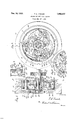
Dec. 19, 1933. T. 1.. FAWICK SPRING ENGAGED SHOE CLUTCH Filed May 27, 1931 Patented Dec. 19, 1933 v v SPRING-ENGAGED SHOE CLUTCH Thomas L. Fawick, Akron, ()hio as'signor to Fa wick- Manufacturing. Company, Waukesha, Wis., a corporation of Wisconsin ApplicatlonMay 27, 1931. Serial No. 540,229
for use in automobile vehicles, and to. reduceor pin being'retained againstxendwisedisplacement eliminate the necessity for adjusting the shoes by means of cars 29 formed on the side plates of; to compensate for wear of the friction 'surfaces. the shoe body which is operated by said link and Of theaccompanying'drawing, Fig. 1 is a 1on'- projecting radially inward therefrom. This argitudinalsection of a clutch embodying the presrangement avoids the use of separate retaining 1o ent invention in a preferred form. means" for the pin'26. The outer pivot pin 27 2 is a rear elevation from the plane 24-2. may be detachably retained against endwise of Fig. 1, partly broken away and in section. movement by suitable 'meansincluding a cotter 3, isa partial longitudinal section showing pin 30. v. g 1 amodiflcation. y Each shoe-operating' lever 24 is provided on 15 Fig, 4 is? a partial rearelevation and section. the end opposite to its linked end, as in' my 'afora 7 of said modification. Y Y 7 said prior;v application, with a weight block 31 se- In the drawing,. 10 isa rotary driving member, cured between the lever, plates by means of rivets such as the flywheel of an' internal combustion 32. The imassj of this block, added to theweight engine, having a-flang e 11 provided with an inof the, associated parts onthe same side of the $0 ternal cylindrical friction surface. :12 is the pivot pin'16,enables the lever 24 to counter-'75 driven shaft whose forward end is supported by' balance theefiect of centrifugal force upon the anlanti friction pilot bearing 13v in the web ,of short arm of said lever and its link and the free the flywheel. end "of the shoe connected with saidlink.
- 14 is. three-armed spider whose hub is con-. {According to my present invention, .1 provide 25. nected ,by splines 15 in non-turning engagement a shoeprojecting spring connecting each of the so withthe shaft 12 for supporting the friction shoes shoes. 1'7 7 with ,the arm of the" lever 24 located andtheiroperating levers. On pivot pins 16at radially ix'iwardfrorn said shoe. These springs 33 the endsofthe spider arms are mounted the outashere shown are of the laminated leaf'type, each wardly-engaging friction shoes 17 here shown having a hooked inner .end 34 anchored around 7 asthree in number, although the number might a, cross pin 35 which connects the side plates of 5 be varied, Each shoe comprises a body including the lever 24, and'a slightly curved outer end 7 an arcuate foundation plate 18 to which the fric bearing against the inner side of the foundation tion facings 19 are secured, and side plates 20 plate 18 of theshoe nearlits linked connection 7 attached to said foundation plate in a suitable with the nest lever 24 which operates said shoe. gdmanner as by spot welding. The shoe bodies Inits unstressed-condition, each of these springs straddle-the ends of the spider, arms and are is substantially straightbut isplaced under tenprovided with perforated reinforcing plates 21 sion to exert the; desired outward pressure on welded to the side plates and surrounding the the, shoe bybending it around a bearing corner pivot pins 16. Each pin is detachably secured in 134 of the weight block 31. v 40 non-turning relation to the rearside plate of the For actuating the levers 24 topositively retract shoe body by meansof a U-shaped retaining clip the shoes 17 against the pressure of their springs 22fastened to said plate by a screw 23'and hav- 33, .1; form each of the. weight blocks 31 with a ing its legs engaged in opposite parallel fiatrearwardly-projecting arm 37 which carries "a: bottomed grooves near the end of thepin sub-J roller 38 mounted in a radial longitudinalplane stantlally as described in my prior application and located in the pathlof a rearwardly-acting iallio. 417,422, filed Dec. 30, 1929,'patented cam or cone element 39 formed on a sleeve 40 March 1 1932, No.-1,847,389. H v surrounding the driven shaft 12 and slidable lon- Also pivoted on the pins 16 and straddlinglthe gitudinally thereon." Said sleeveis heldby a key ends of the spider arms are a series of shoe-actu- 41in non-turningf relation. to the shaft and is 50 ating levers 24 each of which a short arm adapted to be actuated through a ball bearing adapted to operate the shoe 1'7 next adjacent to 42 a clutch throw-out collar 43 connected with the one on whose pivot pin the lever is mounted, the usual pedaifinot shown). The sleeve has a through a link 25 connected by an inner pivot pin cam shoulder for each of the roller arms 37, and 26 with the lever arm, and by an outer pivot pin extending forwardlybeyond each of said shoul- P5 2.7 with the shoe. a 1 3 ders is ahorizontalportionlor horn 44 projecting engage the rollers 38 to turn the levers'24 on their.
pivots, thereby drawing inwardly the free ends of the shoes to which they are linked,against the pressure of the springs 33,the rollers being permitted to ride on the horizontal horns 44 during full retraction of the shoes.
This clutch is shown without any adjustment for taking up wear, although one might obviously be provided if desired. Asthe clutch facings 19 Wear down, the rollers 38 simply move-inwardly closer to the cam shoulders-39 in the forward position of the sleeve so that they are engaged by said shoulders earlier in the rearward stroke 25" of, the sleeve, the original gap between the two being sufficient to allow for a considerable amount of wear.
The invention is not wholly restricted to a rearward engagement of the control sleeve with the levers or their shoe-operating devices, and
various changes of embodiment might be'made without departing from the scope of the claims. In the modification illustrated in Figs. 3 and 4,
outwardly-engaging pivoted friction shoes 17,
counterbalanced operating levers 24 and connecting links 25 are shown in substantially the same form and arrangement as previously described. In this case a counterweight 31 having ,arcuate edge faces is shown, riveted between the side plates of lever 24 andforming a middle bearing or abutment for the laminated shoe-projecting spring 33**. One end of said spring bears outwardly on the shoe 1'7 as before, and the other end is hooked under the shoe and lever pivot pin 16. A secondary angular operating lever 45, one for each shoe and main lever, is pivoted at 46 between ears on a collar4'7 fixed to the hub of the shoe-supporting spider 14 said lever having'a horizontal arm engaging'under the counterweight 31 and a radial arm engaged by a ballclutch is engaged exerts a servo action tending to increase the engaging pressure, and this action greatly reduces the duty required of the springs as compared with an opposite or clockwise rotation of the'driving wheel.
I claim:
'1. In a'f'riction clutch, the combination of a shoe support, a shoe-operating lever pivoted thereto, means for positively effecting ashoeretracting movement of said lever, a friction shoe pivoted at one end to said support, and spring means connecting said lever and a movable portion of the shoe remote from the pivoted end of the latter for yieldingly projecting the latter into operative position. 7
2. In a friction clutch, the combination of a shoe support, a series of shoes pivoted thereon,
a lever pivoted on said support for operating one of said shoes, means for positively effecting a shoe-retracting movement of said lever, and spring means interposed between said lever and a portion of another shoe of the series remote from the latters pivot for yieldingly projecting the latter.
3. In a friction clutch, the combination of a shoe support, a series of radially-acting shoes pivoted to said support, a series of levers pivoted to said support coaxially with the respective shoes and each adapted to operate the next adjacent shoe, and springs interposed between the respective levers and the shoes adjacent to the ones operated by said levers for yieldingly projecting the shoes.
4.1111 a friction clutch, the combination of a radially-acting shoe, a shoe-operating lever weighted to counteract the effect of centrifugal force upon said shoe, an adjacent pivoted shoe, and a spring interposed between the latter and theleverfor yieldingly projecting said adjacent shoe.
5. In a friction clutch, the combination of a shoe-operating lever; means for positively effecting'a shoe-retracting movement of said lever, a pivoted shoe, and a leaf spring interposed between said shoe and lever for yieldin gly projecting the shoe.
6. In a friction clutch, the combination of a shoe support, a series of friction shoes pivoted to said support, a series of shoe-operating levers pivoted to said support, and a series of leaf springs interposed between each of the levers and the shoes next adjacent to the ones oper ated by the levers and anchored upon said levers for yieldingly projecting said shoes. 7
7. In afriction clutch, the combination of a shoe support, an outwardly-acting shoe pivoted to said support,a shoe-operating lever having a weight block for counteracting the effect of centrifugal force upon said shoe, and also having a spring-anchoring member, a second shoe pivoted to said support and a leaf spring having one end'hooked to said member and its other end bearingagainst said second shoe for yieldingly projecting the latter and having an intermediate bearing against said weight block.
8. A driven unit for friction clutches comprising a driven shaft, a shoe-supporting spider thereon, a series of outwardly-acting shoes, shoeoperating levers pivoted on the respective spider arms, springs interposed between the shoes and levers for outwardly projecting the shoes, and a cam sleeve slidable along said shaft for acting on said levers to positively retract theshoes' and having horns projecting beyond its cam portions between the spider arms.
j 9. A driven unit for friction clutches comprising a driven shaft, a shoe-supporting spider thereon, a series of outwardly-acting friction shoes and shoe-operating levers pivoted to the respective arms-of said spider, said levers each having an arm connected with one of the shoes, springs interposed between the other arms of said levers and the next adjacent shoes for yieldingly projecting the latter, and a cam sleeve rearwardly movable along said shaft to engage said other arms of the levers for positively retracting the shoes against the pressure of said springs.
10. A- frictionclutch comprising a shoe includinga body and a pair of side plates, a shoe-op erating lever, and a link connecting said shoe and lever and having a pivot pin at its lever end 10 lie 12. In a friction clutch, the combination of a series of circumferentially-spaced pivoted shoes, a lever pivoted coaxially with one of said shoes for operating the adjacent shoe, and a leaf spring for projecting the first said shoe, said spring having one end anchored on the latter concentrically with the pivot axis thereof and hearing at an intermediate point against said lever.
THOMAS L. FAWICK.
Priority Applications (1)
| Application Number | Priority Date | Filing Date | Title |
|---|---|---|---|
| US540229A US1940407A (en) | 1931-05-27 | 1931-05-27 | Spring-engaged shoe clutch |
Applications Claiming Priority (1)
| Application Number | Priority Date | Filing Date | Title |
|---|---|---|---|
| US540229A US1940407A (en) | 1931-05-27 | 1931-05-27 | Spring-engaged shoe clutch |
Publications (1)
| Publication Number | Publication Date |
|---|---|
| US1940407A true US1940407A (en) | 1933-12-19 |
Family
ID=24154551
Family Applications (1)
| Application Number | Title | Priority Date | Filing Date |
|---|---|---|---|
| US540229A Expired - Lifetime US1940407A (en) | 1931-05-27 | 1931-05-27 | Spring-engaged shoe clutch |
Country Status (1)
| Country | Link |
|---|---|
| US (1) | US1940407A (en) |
Cited By (1)
| Publication number | Priority date | Publication date | Assignee | Title |
|---|---|---|---|---|
| US4653620A (en) * | 1985-05-30 | 1987-03-31 | Canadian Fram Limited | Failsafe fan clutch |
-
1931
- 1931-05-27 US US540229A patent/US1940407A/en not_active Expired - Lifetime
Cited By (1)
| Publication number | Priority date | Publication date | Assignee | Title |
|---|---|---|---|---|
| US4653620A (en) * | 1985-05-30 | 1987-03-31 | Canadian Fram Limited | Failsafe fan clutch |
Similar Documents
| Publication | Publication Date | Title |
|---|---|---|
| US2784811A (en) | Disc brake for vehicles | |
| US3557923A (en) | Multiple disc clutch with cushioned engagement | |
| US1940407A (en) | Spring-engaged shoe clutch | |
| US2082129A (en) | Clutch mechanism | |
| US2589308A (en) | Friction clutch with spring supported pressure plate | |
| US1967322A (en) | Clutch | |
| US2167705A (en) | Clutch mechanism | |
| US2354621A (en) | Clutch | |
| US2277273A (en) | Friction clutch | |
| US2782893A (en) | Friction clutches with torsional resilient mountings | |
| US1865772A (en) | Automatic clutch | |
| US2344690A (en) | Brake | |
| US2100362A (en) | Clutch construction | |
| US6079538A (en) | Clutch mechanism for friction clutch with low declutching force | |
| US1967749A (en) | Automatic clutch | |
| US1610814A (en) | Clutch | |
| US2280357A (en) | Heavy-duty clutch | |
| US2300521A (en) | Friction clutch with radial springs | |
| US891475A (en) | Clutch. | |
| US1912649A (en) | Clutch | |
| US1980512A (en) | Vehicle brake | |
| US2009558A (en) | Clutch | |
| US2212523A (en) | Brake | |
| US1965325A (en) | Friction clutch | |
| US1700244A (en) | Clutch |