US1934603A - Refrigerator - Google Patents
Refrigerator Download PDFInfo
- Publication number
- US1934603A US1934603A US70135A US7013525A US1934603A US 1934603 A US1934603 A US 1934603A US 70135 A US70135 A US 70135A US 7013525 A US7013525 A US 7013525A US 1934603 A US1934603 A US 1934603A
- Authority
- US
- United States
- Prior art keywords
- motor
- compressor
- chamber
- liquid
- casing
- Prior art date
- Legal status (The legal status is an assumption and is not a legal conclusion. Google has not performed a legal analysis and makes no representation as to the accuracy of the status listed.)
- Expired - Lifetime
Links
Images


Classifications
-
- F—MECHANICAL ENGINEERING; LIGHTING; HEATING; WEAPONS; BLASTING
- F25—REFRIGERATION OR COOLING; COMBINED HEATING AND REFRIGERATION SYSTEMS; HEAT PUMP SYSTEMS; MANUFACTURE OR STORAGE OF ICE; LIQUEFACTION SOLIDIFICATION OF GASES
- F25B—REFRIGERATION MACHINES, PLANTS OR SYSTEMS; COMBINED HEATING AND REFRIGERATION SYSTEMS; HEAT PUMP SYSTEMS
- F25B1/00—Compression machines, plants or systems with non-reversible cycle
- F25B1/04—Compression machines, plants or systems with non-reversible cycle with compressor of rotary type
-
- F—MECHANICAL ENGINEERING; LIGHTING; HEATING; WEAPONS; BLASTING
- F25—REFRIGERATION OR COOLING; COMBINED HEATING AND REFRIGERATION SYSTEMS; HEAT PUMP SYSTEMS; MANUFACTURE OR STORAGE OF ICE; LIQUEFACTION SOLIDIFICATION OF GASES
- F25B—REFRIGERATION MACHINES, PLANTS OR SYSTEMS; COMBINED HEATING AND REFRIGERATION SYSTEMS; HEAT PUMP SYSTEMS
- F25B2400/00—Component parts or details not otherwise provided for in this subclass
- F25B2400/07—Details of compressors or related parts
- F25B2400/071—Compressor mounted in a housing in which a condenser is integrated
Definitions
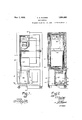
- FIG. 1 is a view, partly in elevation and partly in section, of one form of refrigerator arranged in accordance with my invention
- Fig. 2 is a view, in section, taken on the line 1111 of Fig. 1
- Fig. 3 is an enlarged view, in sectional elevation, of the condensing and compression mechanisms employed in the refrigerator shown in Figures l and 2
- Fig. 4 is a plan view of the condensing and compression mechanisms shown in Fig. 3
- Fig. 5 is a view, partly in elevation and partly in section of the evaporator employed in the refrigerator shown in Figures 1 and 2
- Figure 6 is a view, in sectional elevation, taken on the line VI-VI of Fig. 5.
- the installation of the compression mechanism that is, the compressor and its driving motor, in a single fluid tight casing possesses numerous advantages inasmuch as a very compact arrangement is provided the use of a stufling box is avoided, quiet operation is insured and leakage of the refrigerant fluid is prevented. It is also generally recognized that air cooling is to be preferred to water cooling because it affords an easier method of installation and operation. However, the problem of adequately cooling a totally enclosed compression mechanism in addition to condensing the required amount of refrigerant vapor has provedto be a very difiicult.
- FIG. 1 and 2 I show in Figures 1 and 2 a refrigerator box 10 having an upper or cold storage compartment 11 and a lower compartment 12.
- this lower compartment 12 has been completely filled with the condensing and compression mechanisms.
- my condensing and compression mechanisms are of such compact design and are composed of such few parts that they occupy only a relatively small portion of this lower chamber. Accordingly, I subdivide this lower compartment into a small machinery compartment 13 and a relatively large storage compartment 14.
- the latter compartment is preferably arranged to receive dry stores and the temperature prevailing therein is that of the surrounding atmosphere.
- Within the machinery compartment 13 is located the condensing and compression mechanisms arranged in the form of the unitary structure 15.
- An air inlet 16 is provided in the bottom of the machinery compartment and an air outlet 17 is provided in the rear wall of the compartment.
- a removable cover 18 is provided in the rear of the refrigerator box for permitting the ready removal of the entire unitary structure 15.
- the unitary structure 15 comprises a condensing chamber 20having disposed therein a structure 30 for supporting and housing a compressor 40 together with its driving motor 19.
- the structure 30 forms what may be termed a motor housing 21 and a lubricant receptacle 22.
- the motor 21 is provided with a shaft 23 having a hollow portion 24 and this shaft is directly connected through a suitable coupling 25 to the compressor shaft 26.
- the shafts 23 and 26 are supported in a lower bearing 27 an intermediate bearing 28 and upper bearings '29 and 29'.
- the lower bearing 27 is located in a removable cover plate 31 provided in the condensing chamber 20 for permitting access to the compressor and the motor.
- the intermediate bearing 28 is supported by the, structure 30 while the upper bearings 29 and 29' are provided in the housing of the compressor 40.
- the compressor 40 ' is provided with an inlet port 32 and a discharge port 33. Located directly above the outlet port 33 is a bafiie'33 which is so arranged that any liquid discharged through the port 33 is impinged thereon and deflected into the lubricant receptacle 22.
- a bafiie'33 which is so arranged that any liquid discharged through the port 33 is impinged thereon and deflected into the lubricant receptacle 22.
- An inlet 36 is provided in the lower portion of the condensing chamber 20. This inlet communicates with the hollow portion 24 of the motor shaft 23.
- the latter has provided in its upper portion a plurality of outlets 37 which communicate through a passage 38 with the inlet port 32 of the compressor.
- Lubricant is conveyed to the working parts of the compressor 18 by inverted tubes 39 and 39' which communicate with the lower portion of the receptacle 22.
- Lubricant is supplied to the intermediate bearing 28 through a radially disposed hole 41 which communicates with the hollow portion 24 of the motor shaft.
- This hole 41 connects with a, groove 42 arranged helically about the motor shaft in such a direction that the rotation of the motor shaft causes the lubri-- .cant to be forced upwardly into. the bearing 28.
- a lubricant arrester 43 is provided on the motor shaft 23 for collecting any lubricant which may be discharged from the lower end of the bearing 28. No special means are provided for lubricating the lower bearing 27 other than that the inlet 36 to the compression mechanism is so arranged that the fluid passing therethrough is impinged upon this hearing. Any lubricant accumulating in the motor housing 21 is drained through a restricted orifice 44 to the inlet passage 36.
- the exterior surface of the condensing chamber 20 is provided with a very large number of heat radiating fins 45 having a jacket 46 tightly surrounding the same.
- the jacket 46 is open at its lower end 47 for the admission of air but is provided at its upper end with a cover plate 48 having disposed centrally therein an air outlet 50.
- Projecting into the upper portion of the condensing chamber 20 is a housing 49 having disposed therein a motor 51 for driving a blower 52. Fixed in the housing 49 is a shaft 53 upon which is supported a sleeve 54 for connecting the motor to the blower.
- the housing 49 has its lower portion arranged to hold a substantial body of lubricating fluid having a level such as indicated at 55 and a baflie 56 is interposed between the lubricant portion of the housing and the motor 51.
- the sleeve 54 is supported upon the housing 49 by a suitable thrust bearing 57 which is immersed in the lubricant.
- Lubricating liquid is having, as shown in Fig. 4, a tangential outlet 63.
- This tangential outlet is so arranged in the refrigerator box that it communicates with the air outlet 17 provided in the refrigerator box 10.
- the outlet 34 of 10 the condensing chamber communicates through a conduit 64 with an evaporator 65 provided in the cold storage compartment 11.
- a float valve 66 is provided in the conduit 64 for controlling the flow of the liquid therethrough.
- the evaporator 65 comprises an expansion chamber 67 and a freezing chamber 68 containing some noncongealable liquid such as alcohol and water.
- a container 69 Disposed within the freezing chamber 68 is a container 69 upon which is supported a plurality of molds 71 in whichv ice may be formed.
- a surge tank 72- which communicates with the expansion chamber and which contains a level of liquid working fluid such as indicated at 73.
- An outlet 74 is provided in the surge tank, which outlet is provided with a conduit 75 projecting into the surge tank. The entrant portion of this conduit is disposed below the level of the liquid 73.
- Surrounding the conduit 75 is an inner sleeve 76 having vapor inlets 77 provided in its upper portion, the portion extending below the level of the liquid 73 being fluid tight with the exception of a small aperture 78.
- Surrounding the sleeve 76 is an outer sleeve 79 which is open at its upper end 81 for the admission of vapor and at its lower end 82 for the admission of liquid. Suitable strainer material 83 covers both the liquid and vapor inlets 81 and 82.
- the outlet 74 from the surge tank communicates through a conduit 84 with the inlet 36 provided in the condensing chamber.
- liquid working fluid completely fills the expansion chamber 67 of the evaporator and the surge tank 72 to the level indicated at 73. Liquid also completely fills the receptacle 22 as well as the condensing chamber 20 to the level indicated at 35 while some liquid is contained in the float chamber 66.
- the liquid working fluid which I prefer to employ consists of a refrigerant and a lubricant which together form a physical solution separable only by vaporization and disclosed in a co-pending application of mine, serially numbered 617,844, filed February 8, 1923, and entitled Working fluid for refrigeration.
- the action of the compressor 18 maintains a 150 pressure sufiiciently low in the expansion chamber 67 of the evaporator to induce vaporization of the liquid working fluid contained therein.
- heat is absorbed from the cold storage compartment 11 of the refrigerator box 10 and from the non-congealable liquid contained in the freezing chamber 68.
- most domestic refrigerating machines operate only intermittently in response to the tempera- -ture prevailing within the refrigerator box,- an
- evaporator of the form illustrated possesses many advantages in that heat is absorbed from the interior of the refrigerator box. directly through the outer walls of the expansion chamber while the ice molds 71 are surrounded by a chamber containing a substantial body of non-congealable liquid.
- This arrangement permits heat to be conducted directly from the refrigerator box to the expansion chamber and it also prevents melting of the ice during the idle peniods of the machine because of the relatively large cold storage capacity of the freezing chamber.
- the refrigerator box is cooled by the direct method of expansion while ice is formed by the indirect method, thus providing an ideal arrangement.
- the vapor generated in the expansion chamber 67 rises upwardly through the liquid and enters the upper portion of the surge tank 72.
- the surge tank 72 is arranged above the expansion chamberand contains a substantial body of liquid working fluid so as to insure the expansion chamber being completely filled with liquid at all times. Surging of the liquid incident to the boiling process is completely absorbed in the expansion chamber while the foam thus created is segregated in the upper portion of the surge tank.
- the expansion chamber therefore contains a solid body of liquid at all times.
- the surge tank further prevents solid slugs of liquid from being carried through the outlet 74 to the compressor.
- the vapor accumulating in the upper portion of the surge tank 72 is drawn through the strainer 83 and through the inlets 81 and 77 provided in the outer and inner sleeves 79 and 76 respectively to the interior of the inner sleeve 76. Within this sleeve, the vapor passes downwardly to the entrant portion of the outlet conduit 75 and thence passes to the outlet 74. During the passage of the vapor, there is a constant and uniform entrainment of liquid working fluid in the vapor as permitted by the flow of the liquid v through the aperture 78.
- a working fluid consisting of a refrigerant and a lubricant which together form a physical solution andI therefore maintain a constant circulation of this liquid through the evaporator by my entrainment process.
- This entrainment performs two functions in that segregation of the lubricant within the evaporator is avoided and the entrained liquids seals and lubricates the compression mechanism in passing therethrough.
- This novel method of entraining a liquid working fluid in the refrigerant vapor passing to the compressor is disclosed in a co-pending application of mine; serially'numbered 550,445, filed April 7, 1922 and entitled Refrigerators.
- the refrigerant vapor is discharged from the compressor 40 through the discharge port 33 at a higher pressure and impinged against the baffle 33. This action causes the liquid contained in the vapor to be separated therefrom and this liquid falls downwardly into the lubricant receptacle 22.
- the liquid in the receptacle 22 surrounds the compressor 17 and absorbs the heat generated thereby, the heat thus absorbed being suflicient to vaporize off the refrigerant component of the liquid working fluid, leaving a body of liquid in the receptacle 22 which is substantially a lubricant.
- I provide a distillation process for producing a lubricating fluid, which distillation process absorbs the heat generated by the compression mechanism as well as some of the heat generated by the motor.
- This novel method of producing a lubricant fluid is disclosed in a co-pending application of mine seriallynumbered 643,364, filed June 4, 1924 and entitled Refrigerators.
- the lubricating fluid accumulating in the receptacle 22 is conveyed by the inverted tubes 39 and 39 to the'respective stages of the compressor for sealing and lubricating thesame.
- the flow of lubricant through these tubes is induced by the difference in pressure prevailing between the condensing chamber and the interior of the respective stages of the compressor.
- the lubricant percolates through the various working clearances provided in the compressor and accumulates in the lower portion of the receptacle 22.
- the rotation of the blower 52, which is driven by the motor 51, causes a constant current of air to be drawn through the opening 16 in the bottom of the refrigerator box upwardly over the circular walls as well as the upper end wall of the condensing chamber. In this way, relatively cold air is obtained and the well known advantages of the contra-flow principle obtained. Heat is abstracted from the refrigerant vapor in the condensing chamber and the condensate thus produced accumulates in the lower portion of the chamber.
- the air having passed over the condensing chamber, is brought into contact with the motor 51 for absorbing the heat generated by its operation.
- the warm air is drawn through the outlet 50 and is discharged tangentially by the outlet 63 through the hole 17 in the back of the refrigerator box.
- I have provided a very large number of heat radiating fins.
- I provide a jacket which surrounds these radiating fins so that heat is dissipated to the air, not only by the fins, but by the jacket as well.
- the jacket not only serves to direct the passage of air over the condensing chamber but, augments the heat radiating capacity of the fins. This is a, very desirable feature in that it assures lower condensing pressures and consequently less current consumption.
- this condensate Upon sufficient accumulation of condensed refrigerant in the lower portion of the condensing chamber, this condensate enters the outlet 35 and is conveyed by the conduit 64 toward the evaporotor. Upon sufficient accumulation of liquid in the float chamber 66, the float valve acts to permit this liquid to be drawn into the evaporator in a manner well understood in the art. Any excess lubricating liquid which may accumulate in the receptacle 22 overflows into the condensing chamber and passes on to ,the evaporator with the condensed refrigerant. The body of condensate surrounding the motor housing assists in absorbing the heat generated by the motor.
- the housing 49 of the blower motor 51 contains a substantial body of lubricant.
- This lubricant is carried upwardly between the shaft 53 and the sleeve 54 by the spiral groove 59. Upon reaching the upper portion of the shaft 53, it returns to the lower portion of the housing through the hollow interior of the shaft and through the radial holes 62.
- the thrust bearing 57 being immersed in the body of lubricant contained in the housing 49, thorough lubrication of all the bearings assocated with the blower motor is assured.
- the lubrication of the blower motor as well as of the compression mechanism within the condensing chamber is automatic and is so arranged that it will operate effectively and reliably for extended periods of time without care or attention.
- a compressor for driving the compressor, a fluid tight casing enclosing both the motor and the compressor, heat radiating projections provided on the casing, a jacket encircling the projections, and means provided in an end portion of the casing for passing air between the casing and the jacket.
- a compressor for driving the compressor, a fluid tight casing enclosing both the motor and the compressor and defining a condensing chamber, heat radiating projections provided on the casing, a jacket encircling the projections, and means disposed at a higher elevation than the condensing chamber for drawing air upwardly between the jacket and the condensing chamber.
- a compressor for driving the compressor, a fluid tight casing enclosing both the motor and the compressor, a depression provided in the casing, and means partly located in the depression for circulating air over the casing.
- a casing defining a condensing chamber, a depression provided in the casing, a motor located in the depression, and a fan driven by the motor for passing air over the condensing chamber.
- a refrigerating apparatus the combination of an evaporator, a compressor, a motor, a casing forming a condensing chamber, a depression provided in the upper surface of the casing, a motor located in the depression, and a fan disposed above the motor and driven thereby for passing air over the condensing chamber.
- a refrigerating apparatus the combination of an evaporator, a compressor, a motor for driving the compressor, a cylindrical casing forming a condensing chamber and enclosing the motor and the compressor, a depression provided in one-of the end walls of the casing, a motor. disposed in the depression, and a fan driven by the motor for drawing air over the condensing chamber.
- a condenser for a compression refrigerating apparatus the combination of a casing, a lubricant containing receptacle associated with the casing, a supporting member fixed in the receptacle, a motor connected to a fan and rotatable upon the fixed member, and means associated with the motor for effecting a circulation of lubricant between the motor and the fixed member.
- a condenser for a compression refrigerating apparatus the combination of a casing, a lubricant containing receptacle provided in the casing, a shaft secured in the receptacle, 9. motor rotatable upon the shaft, a blower connected to the motor, and means actuated by the motor for circulating lubricant between the shaft and the motor.
- a condenser for a compression refrigerating apparatus the combination of a casing, a receptacle having a body of lubricant contained in its lower portion, a fixed shaft disposed in substantially a'vertical position within the receptacle, a motor having bearings rotatable about the shaft, a blower connected to the motor, and means provided in one of the motorbearings for conveying lubricant from the receptacle upwardly between the shaft and the motor bearings.
- a compressor for driving the compressor, a condenser, a fluid-tight casing enclosing both the motor and the compressor, heat radiating projections provided on the casing, a jacket surrounding the heat radiating projections, and means associated with the upper portion of the casing for drawing air upwardly between the casing and the jacket and for discharging it tangentially from the upper portion of the casing.
- an evaporator for the storage box of a refrigerating apparatus the combination of a cold storage chamber, an expansion chamber having heat conducting surfaces disposed in direct heat exchanging relation with both the interior of the storage box and the cold storage chamber, means associated with the cold storage chamber for forming. ice, a surge tank located on the top of the expansion chamber, refrigerant fluid inlet means provided at the bottom of the expansion chamber, and refrigerant fluid outlet means provided in the surge tank.
- a cooling unit comprising a vaporizer containing volatile liquid refrigerant, a closed brine containing chamber arranged interiorly of said vaporizer and substantially submerged in the liquid refrigerant, an open end freezing chamber interior of said brine chamber, and a removable water container within said freezing chamber.
- a cooling unit comprising a vaporizer containing volatile liquid refrigerant, a freezing chamber arranged interiorly of said vaporizer and accessible from the exterior of said vaporizer, heat absorbing means entirely enclosed intermediate said chamber and the refrigerant in said vaporizer, and a removable container in said freezing chaminner shell forming a storage chamber, said vaporizer wall and inner shell having registering openings, and a slidable container for said storage chamber.
- a cooling unit therein comprising a plurality of cup-like receptacles nested one within the other, adjacent receptacles being spaced from each other to form chambers surrounding the inner recaptacle, the edges of the mouths of said receptacles being formed of such size as to closely fit one within the other, means for securing said edges together, a liquid in one of said chambers, and means for supplying refrigerant to another of said chambers.
- a cooling unit therein comprising a plurality of cup-like receptacles nested one within the other, adjacent receptacles being spaced from each other to form chambers surrounding the inner receptacle, the edges of the mouths of said receptacles being formed of such size as to closely fit one within the other, and means for securing said edges together.
- a fluid-tight casing enclosing both the motor and the compressor, heat radiating projections provided on the casing, a jacket encircling the projections, and a fan provided in an end portion of the jacket for effecting a forced circulation of air between the casing and the jacket.
- a refrigerator cabinet and a machinery cabinet said machinery cabinet having an air inlet and an air outlet spaced from the inlet, an evaporator disposed in the refrigerator cabinet, a duct disposed within the machinery cabinet and formed separately therefrom for directing air from the inlet toward the outlet, a fan for circulatingair from the inlet and through the duct to the outlet, and a condenser and a motor-driven compressor both disposed in the machinery cabinet directly in the path of the circulating air.
Landscapes
- Engineering & Computer Science (AREA)
- Physics & Mathematics (AREA)
- Mechanical Engineering (AREA)
- Thermal Sciences (AREA)
- General Engineering & Computer Science (AREA)
- Cold Air Circulating Systems And Constructional Details In Refrigerators (AREA)
- Devices That Are Associated With Refrigeration Equipment (AREA)
Description
Nov. 7, 1933.
Original Filed Nov. 19, 1925 A. KUCHER REFRI GERAT OR ee 1 l WITNESS 3 Sheets- Sheet l a I g E E 1 INVENTOR ATTORNEY Nov. 7, 1933- A. A. KUCHER 1,934,603
REFRIGERATOR Original Filed Nov. 19, 1925 3 Sheets-Sheet 2 AH. Kucher lNVENTOR ATTORN EY WITNESS NOV. 7, 1933. A. KUCHER 1,934,603
REFRIGERATOR Original Filed Nov. 19, 1925 3 Sheets-Sheet 5 lNVENT M g' ATTORNEY Patented Nov. 7, 1933 REFRIGERATOR Andrew A. Kucher, Dayton, Ohio, assignor to Westinghouse Electric & Manufacturing Company. a corporation of Pennsylvania Application November 19, 1925, Serial No. 70,135 Renewed June 10, 1933 19 Claims. (Cl. 62-116) My invention relates to refrigerating machines and particularly to small capacity machines of the compression type which are suitable for household use and it has for an object to provide apparatus of the character designated which shall operate reliably and effectively for extended periods of time. It has for a further object to provide a refrigerating machine which shall embody a novel structure for condensing the refrigerant l0 vapor and for dissipating the heat generated by the compression mechanism.
These and other objects, which will be made apparent throughout the further description of my invention, may be attained by the employment of the apparatus hereinafter described and illustrated in the accompanying drawings in which Fig. 1 is a view, partly in elevation and partly in section, of one form of refrigerator arranged in accordance with my invention; Fig. 2 is a view, in section, taken on the line 1111 of Fig. 1; Fig. 3 is an enlarged view, in sectional elevation, of the condensing and compression mechanisms employed in the refrigerator shown in Figures l and 2; Fig. 4 is a plan view of the condensing and compression mechanisms shown in Fig. 3; Fig. 5 is a view, partly in elevation and partly in section of the evaporator employed in the refrigerator shown in Figures 1 and 2 and Figure 6 is a view, in sectional elevation, taken on the line VI-VI of Fig. 5.
The installation of the compression mechanism, that is, the compressor and its driving motor, in a single fluid tight casing possesses numerous advantages inasmuch as a very compact arrangement is provided the use of a stufling box is avoided, quiet operation is insured and leakage of the refrigerant fluid is prevented. It is also generally recognized that air cooling is to be preferred to water cooling because it affords an easier method of installation and operation. However, the problem of adequately cooling a totally enclosed compression mechanism in addition to condensing the required amount of refrigerant vapor has provedto be a very difiicult.
one where it is desired to utilize air and not watef as the heat absorbing medium. I
I have, however, conceived the idea of providing heat radiating fins upon the exterior surface of the casing enclosing the compressor and the motor and of superimposing a fan or blower above this casing so that air may be circulated thereover and sufiicient heat abstracted to both condense the' refrigerant vapor discharged by the compressor as well as to absorb the heat of the compression mechanism. In addition, I so arrange the fan or blower that the air is drawn upwardly over the casing or, what may be termed the condensing chamber, and discharged at its upper portion. In this way, air from below the condensing chamber which has a relatively low temperature is obtained and this air makes no contact whatsoever with the motor employed for driving the fan until such time as it has passed completely over the condensing chamber. Furthermore, by' condensing the refrigerant vapor within the casing enclosing the motor and the compressor, the condensate created in the casing may be readily utilized'to absorb the heat generated by the compression mechanism. I have also associated with the condensing chamber a novel structure for retaining the fan together with its driving motor in the upper portion'of the chamber as well as means for automatically supplying lubricant to the bearings of the fan motor. These and other features, which will be described hereafter, cooperate to provide a refrigerating machine well adapted for domestic installation and for effective operation under the exacting requirements of household use.
Referring to the drawings for a more detailed description of my invention, I show in Figures 1 and 2 a refrigerator box 10 having an upper or cold storage compartment 11 and a lower compartment 12. In most refrigerating machines heretofore constructed, this lower compartment 12 has been completely filled with the condensing and compression mechanisms. However, my condensing and compression mechanisms are of such compact design and are composed of such few parts that they occupy only a relatively small portion of this lower chamber. Accordingly, I subdivide this lower compartment into a small machinery compartment 13 and a relatively large storage compartment 14. The latter compartment is preferably arranged to receive dry stores and the temperature prevailing therein is that of the surrounding atmosphere. Within the machinery compartment 13 is located the condensing and compression mechanisms arranged in the form of the unitary structure 15. An air inlet 16 is provided in the bottom of the machinery compartment and an air outlet 17 is provided in the rear wall of the compartment. A removable cover 18 is provided in the rear of the refrigerator box for permitting the ready removal of the entire unitary structure 15.
As shown in Figures 3 and 4, the unitary structure 15 comprises a condensing chamber 20having disposed therein a structure 30 for supporting and housing a compressor 40 together with its driving motor 19. The structure 30 forms what may be termed a motor housing 21 and a lubricant receptacle 22. The motor 21 is provided with a shaft 23 having a hollow portion 24 and this shaft is directly connected through a suitable coupling 25 to the compressor shaft 26. The shafts 23 and 26 are supported in a lower bearing 27 an intermediate bearing 28 and upper bearings '29 and 29'. The lower bearing 27 is located in a removable cover plate 31 provided in the condensing chamber 20 for permitting access to the compressor and the motor. The intermediate bearing 28 is supported by the, structure 30 while the upper bearings 29 and 29' are provided in the housing of the compressor 40.
The compressor 40 'is provided with an inlet port 32 and a discharge port 33. Located directly above the outlet port 33 is a bafiie'33 which is so arranged that any liquid discharged through the port 33 is impinged thereon and deflected into the lubricant receptacle 22. Provided in the lower portion of the condensing chamber 20 is an outlet 34 having a portion 35 projecting upwardly into the condensing chamber so as to maintain a level of condensed refrigerant about the motor 19, such as indicated at 35'. An inlet 36 is provided for the compression mechanism in the removable cover plate 31. This inlet communicates with the hollow portion 24 of the motor shaft 23. The latter has provided in its upper portion a plurality of outlets 37 which communicate through a passage 38 with the inlet port 32 of the compressor.
Lubricant is conveyed to the working parts of the compressor 18 by inverted tubes 39 and 39' which communicate with the lower portion of the receptacle 22. Lubricant is supplied to the intermediate bearing 28 through a radially disposed hole 41 which communicates with the hollow portion 24 of the motor shaft. This hole 41 connects with a, groove 42 arranged helically about the motor shaft in such a direction that the rotation of the motor shaft causes the lubri-- .cant to be forced upwardly into. the bearing 28.
A lubricant arrester 43 is provided on the motor shaft 23 for collecting any lubricant which may be discharged from the lower end of the bearing 28. No special means are provided for lubricating the lower bearing 27 other than that the inlet 36 to the compression mechanism is so arranged that the fluid passing therethrough is impinged upon this hearing. Any lubricant accumulating in the motor housing 21 is drained through a restricted orifice 44 to the inlet passage 36.
The exterior surface of the condensing chamber 20 is provided with a very large number of heat radiating fins 45 having a jacket 46 tightly surrounding the same. The jacket 46 is open at its lower end 47 for the admission of air but is provided at its upper end with a cover plate 48 having disposed centrally therein an air outlet 50. Projecting into the upper portion of the condensing chamber 20 is a housing 49 having disposed therein a motor 51 for driving a blower 52. Fixed in the housing 49 is a shaft 53 upon which is supported a sleeve 54 for connecting the motor to the blower. The housing 49 has its lower portion arranged to hold a substantial body of lubricating fluid having a level such as indicated at 55 and a baflie 56 is interposed between the lubricant portion of the housing and the motor 51. The sleeve 54 is supported upon the housing 49 by a suitable thrust bearing 57 which is immersed in the lubricant. Lubricating liquid is having, as shown in Fig. 4, a tangential outlet 63.
This tangential outlet is so arranged in the refrigerator box that it communicates with the air outlet 17 provided in the refrigerator box 10.
From the foregoingdescription it is apparent that the condensing and compression mechanisms of my refrigerator are very compactly and symmetrically arranged in that both driving motors as well as the compressor and the blower are arranged co-axial and in end-to-end relation. It is believed that my arrangement provides a refrigerating machine having a minimum number of working parts and which is, comparatively speaking, inexpensive to manufacture.
As shown in Figures 1 and 2, the outlet 34 of 10 the condensing chamber communicates through a conduit 64 with an evaporator 65 provided in the cold storage compartment 11. A float valve 66 is provided in the conduit 64 for controlling the flow of the liquid therethrough. As shown in Figures 5 and 6, the evaporator 65 comprises an expansion chamber 67 and a freezing chamber 68 containing some noncongealable liquid such as alcohol and water. Disposed within the freezing chamber 68 is a container 69 upon which is supported a plurality of molds 71 in whichv ice may be formed. Superimposed upon the expansion chamber 67 is a surge tank 72- which communicates with the expansion chamber and which contains a level of liquid working fluid such as indicated at 73. An outlet 74 is provided in the surge tank, which outlet is provided with a conduit 75 projecting into the surge tank. The entrant portion of this conduit is disposed below the level of the liquid 73. Surrounding the conduit 75 is an inner sleeve 76 having vapor inlets 77 provided in its upper portion, the portion extending below the level of the liquid 73 being fluid tight with the exception of a small aperture 78. Surrounding the sleeve 76 is an outer sleeve 79 which is open at its upper end 81 for the admission of vapor and at its lower end 82 for the admission of liquid. Suitable strainer material 83 covers both the liquid and vapor inlets 81 and 82. As shown in Figures 1 and 2, the outlet 74 from the surge tank communicates through a conduit 84 with the inlet 36 provided in the condensing chamber.
The operation of the above embodiment of my invention is as follows:-Assuming the refrigerating machine to be in operation, liquid working fluid completely fills the expansion chamber 67 of the evaporator and the surge tank 72 to the level indicated at 73. Liquid also completely fills the receptacle 22 as well as the condensing chamber 20 to the level indicated at 35 while some liquid is contained in the float chamber 66. The liquid working fluid which I prefer to employ consists of a refrigerant and a lubricant which together form a physical solution separable only by vaporization and disclosed in a co-pending application of mine, serially numbered 617,844, filed February 8, 1923, and entitled Working fluid for refrigeration.
The action of the compressor 18 maintains a 150 pressure sufiiciently low in the expansion chamber 67 of the evaporator to induce vaporization of the liquid working fluid contained therein. In the vaporization process, heat is absorbed from the cold storage compartment 11 of the refrigerator box 10 and from the non-congealable liquid contained in the freezing chamber 68. As most domestic refrigerating machines operate only intermittently in response to the tempera- -ture prevailing within the refrigerator box,- an
evaporator of the form illustrated possesses many advantages in that heat is absorbed from the interior of the refrigerator box. directly through the outer walls of the expansion chamber while the ice molds 71 are surrounded by a chamber containing a substantial body of non-congealable liquid. This arrangement permits heat to be conducted directly from the refrigerator box to the expansion chamber and it also prevents melting of the ice during the idle peniods of the machine because of the relatively large cold storage capacity of the freezing chamber. In other words, the refrigerator box is cooled by the direct method of expansion while ice is formed by the indirect method, thus providing an ideal arrangement.
Referring to Figures 5 and 6, the vapor generated in the expansion chamber 67 rises upwardly through the liquid and enters the upper portion of the surge tank 72. The surge tank 72 is arranged above the expansion chamberand contains a substantial body of liquid working fluid so as to insure the expansion chamber being completely filled with liquid at all times. Surging of the liquid incident to the boiling process is completely absorbed in the expansion chamber while the foam thus created is segregated in the upper portion of the surge tank. The expansion chamber therefore contains a solid body of liquid at all times. The surge tank further prevents solid slugs of liquid from being carried through the outlet 74 to the compressor.
The vapor accumulating in the upper portion of the surge tank 72 is drawn through the strainer 83 and through the inlets 81 and 77 provided in the outer and inner sleeves 79 and 76 respectively to the interior of the inner sleeve 76. Within this sleeve, the vapor passes downwardly to the entrant portion of the outlet conduit 75 and thence passes to the outlet 74. During the passage of the vapor, there is a constant and uniform entrainment of liquid working fluid in the vapor as permitted by the flow of the liquid v through the aperture 78. As stated heretofore, I prefer to employ a working fluid consisting of a refrigerant and a lubricant which together form a physical solution andI therefore maintain a constant circulation of this liquid through the evaporator by my entrainment process. This entrainment performs two functions in that segregation of the lubricant within the evaporator is avoided and the entrained liquids seals and lubricates the compression mechanism in passing therethrough. This novel method of entraining a liquid working fluid in the refrigerant vapor passing to the compressor is disclosed in a co-pending application of mine; serially'numbered 550,445, filed April 7, 1922 and entitled Refrigerators.
' The refrigerant vapor, having entrained therein a quantity of liquid working fluid, is drawn through the conduit 84, Figures 1 and 2, .and enters the condensing chamber through the inlet 36, Figure 3. It then is drawn upwardly through the hollow portion 24 of the motor shaft 23 and pressor.
passes through the holes 37 into the passage 38 connecting with the inlet port 32 of the compressor. In entering the hollow portion 24 of the motor shaft 23, the liquid entrained in the vapor serves to lubricate the lower bearing 27.
The refrigerant vapor is discharged from the compressor 40 through the discharge port 33 at a higher pressure and impinged against the baffle 33. This action causes the liquid contained in the vapor to be separated therefrom and this liquid falls downwardly into the lubricant receptacle 22. The liquid in the receptacle 22 surrounds the compressor 17 and absorbs the heat generated thereby, the heat thus absorbed being suflicient to vaporize off the refrigerant component of the liquid working fluid, leaving a body of liquid in the receptacle 22 which is substantially a lubricant. In other words, I provide a distillation process for producing a lubricating fluid, which distillation process absorbs the heat generated by the compression mechanism as well as some of the heat generated by the motor. This novel method of producing a lubricant fluid is disclosed in a co-pending application of mine seriallynumbered 643,364, filed June 4, 1924 and entitled Refrigerators.
The lubricating fluid accumulating in the receptacle 22 is conveyed by the inverted tubes 39 and 39 to the'respective stages of the compressor for sealing and lubricating thesame. The flow of lubricant through these tubes is induced by the difference in pressure prevailing between the condensing chamber and the interior of the respective stages of the compressor. The lubricant percolates through the various working clearances provided in the compressor and accumulates in the lower portion of the receptacle 22.
cation of the intermediate bearing 28' I have provided the hole 41 which is disposed at the lower end of the bearing and which throws outwardly, by centrifugal force, some of the entrained liquid in the vapor passing to the com- This liquid is conveyed upwardly by the spiral groove 42 and passes through the bearing after which it is again entrained in the refrigerant vapor passing to the compressor.
During idle periods of the machine, oil may seep or leak from the receptacle 22 through the working clearances of the compressor and drain downwardly into the intermediate bearing 28. This oil is prevented from falling upon the motor by the arrester 43-. Upon sufficient accumulation of lubricating fluid in the arrester 43, it drains through the hole 41 into the hollow portion 24 of the motor shaft and passes downwardly and enters the lower bearing 27 and the inlet passage 36. If the idle period is of suificient duration, the lubricating fluid fills the inlet passage 36 after which it accumulates in the lower portion of the motor housing 21, the motor housing being capable of retaining, below the motor, all of the lubricant previously contained inthe receptacle 22. Upon restarting of the machine, the liquid contained in the inlet passage 36 is initially drawn in by the compressor and serves to the inlet passage 36 until all of the lubricating fluid is returned to the receptacle 22.
' Refrigerant vapor discharged by the compressor together with the refrigerant vapor generated in the distillation process taking place in the receptacle 22, collects within the condensing chamber 20. The rotation of the blower 52, which is driven by the motor 51, causes a constant current of air to be drawn through the opening 16 in the bottom of the refrigerator box upwardly over the circular walls as well as the upper end wall of the condensing chamber. In this way, relatively cold air is obtained and the well known advantages of the contra-flow principle obtained. Heat is abstracted from the refrigerant vapor in the condensing chamber and the condensate thus produced accumulates in the lower portion of the chamber. The air, having passed over the condensing chamber, is brought into contact with the motor 51 for absorbing the heat generated by its operation. The warm air is drawn through the outlet 50 and is discharged tangentially by the outlet 63 through the hole 17 in the back of the refrigerator box.
Attention is invited to the fact that I have provided a very large number of heat radiating fins. In addition, I provide a jacket which surrounds these radiating fins so that heat is dissipated to the air, not only by the fins, but by the jacket as well. In other words, the jacket not only serves to direct the passage of air over the condensing chamber but, augments the heat radiating capacity of the fins. This is a, very desirable feature in that it assures lower condensing pressures and consequently less current consumption.
Upon sufficient accumulation of condensed refrigerant in the lower portion of the condensing chamber, this condensate enters the outlet 35 and is conveyed by the conduit 64 toward the evaporotor. Upon sufficient accumulation of liquid in the float chamber 66, the float valve acts to permit this liquid to be drawn into the evaporator in a manner well understood in the art. Any excess lubricating liquid which may accumulate in the receptacle 22 overflows into the condensing chamber and passes on to ,the evaporator with the condensed refrigerant. The body of condensate surrounding the motor housing assists in absorbing the heat generated by the motor.
As shown in Figure 3, the housing 49 of the blower motor 51 contains a substantial body of lubricant. This lubricant is carried upwardly between the shaft 53 and the sleeve 54 by the spiral groove 59. Upon reaching the upper portion of the shaft 53, it returns to the lower portion of the housing through the hollow interior of the shaft and through the radial holes 62. The thrust bearing 57, being immersed in the body of lubricant contained in the housing 49, thorough lubrication of all the bearings assocated with the blower motor is assured. The lubrication of the blower motor as well as of the compression mechanism within the condensing chamber is automatic and is so arranged that it will operate effectively and reliably for extended periods of time without care or attention.
While I have shown my invention in but one form, it will be obvious to those skilled in the art that it is not so limited but is susceptible of various changes and modifications, without departing from the spirit thereof, and I desire, therefore, that only such limitationsshall be placed thereupon as are imposed by the prior art or as are specifically set forth in the appended claims.
What I claim is:
1. In a refrigerating apparatus in which a refrigerant fluid is vaporized, compressed and condensed in a repeating cycle, the combination of a compressor, a motor for driving the compressor, a fluid tight casing enclosing both the motor and the compressor, heat radiating projections provided on the casing, a jacket encircling the projections, and means provided in an end portion of the casing for passing air between the casing and the jacket.
2. In a refrigerating apparatus in which a refrigerant fluid is vaporized, compressed and condensed in a repeating cycle, the combination of a compressor, a motor for driving the compressor, a fluid tight casing enclosing both the motor and the compressor and defining a condensing chamber, heat radiating projections provided on the casing, a jacket encircling the projections, and means disposed at a higher elevation than the condensing chamber for drawing air upwardly between the jacket and the condensing chamber.
3. In a refrigerating apparatus in which a refrigerating fluid is vaporized, compressed and condensed in a repeating cycle, the combination of a compressor, a motor for driving the compressor, a fluid tight casing enclosing both the motor and the compressor, a depression provided in the casing, and means partly located in the depression for circulating air over the casing.
4. In a refrigerating apparatus, the combination of an evaporator, a compressor, a motor, a fluid-tight casing surrounding the motor and the compressor and forming a condensing chamber, a depression provided in the casing, and means partly located in the depression for passing air over the condensing chamber.
5. In a refrigerating apparatus, the combination of an evaporator, a compressor, a motor,
,a casing defining a condensing chamber, a depression provided in the casing, a motor located in the depression, and a fan driven by the motor for passing air over the condensing chamber.
6. In a refrigerating apparatus, the combination of an evaporator, a compressor, a motor, a casing forming a condensing chamber, a depression provided in the upper surface of the casing, a motor located in the depression, and a fan disposed above the motor and driven thereby for passing air over the condensing chamber.
'7. In a refrigerating apparatus, the combination of an evaporator, a compressor, a motor for driving the compressor, a cylindrical casing forming a condensing chamber and enclosing the motor and the compressor, a depression provided in one-of the end walls of the casing, a motor. disposed in the depression, and a fan driven by the motor for drawing air over the condensing chamber.
8. In a condenser for a compression refrigerating apparatus, the combination of a casing, a lubricant containing receptacle associated with the casing, a supporting member fixed in the receptacle, a motor connected to a fan and rotatable upon the fixed member, and means associated with the motor for effecting a circulation of lubricant between the motor and the fixed member.
9. In a condenser for a compression refrigerating apparatus, the combination of a casing, a lubricant containing receptacle provided in the casing, a shaft secured in the receptacle, 9. motor rotatable upon the shaft, a blower connected to the motor, and means actuated by the motor for circulating lubricant between the shaft and the motor.
10 In a condenser for a compression refrigerating apparatus, the combination of a casing, a receptacle having a body of lubricant contained in its lower portion, a fixed shaft disposed in substantially a'vertical position within the receptacle, a motor having bearings rotatable about the shaft, a blower connected to the motor, and means provided in one of the motorbearings for conveying lubricant from the receptacle upwardly between the shaft and the motor bearings.
11. In a refrigerating apparatus, the combination of a compressor, a motor for driving the compressor, a condenser, a fluid-tight casing enclosing both the motor and the compressor, heat radiating projections provided on the casing, a jacket surrounding the heat radiating projections, and means associated with the upper portion of the casing for drawing air upwardly between the casing and the jacket and for discharging it tangentially from the upper portion of the casing.
12. In an evaporator for the storage box of a refrigerating apparatus, the combination of a cold storage chamber, an expansion chamber having heat conducting surfaces disposed in direct heat exchanging relation with both the interior of the storage box and the cold storage chamber, means associated with the cold storage chamber for forming. ice, a surge tank located on the top of the expansion chamber, refrigerant fluid inlet means provided at the bottom of the expansion chamber, and refrigerant fluid outlet means provided in the surge tank.
13. In mechanical refrigerating apparatus, a cooling unit comprising a vaporizer containing volatile liquid refrigerant, a closed brine containing chamber arranged interiorly of said vaporizer and substantially submerged in the liquid refrigerant, an open end freezing chamber interior of said brine chamber, and a removable water container within said freezing chamber.
14. In mechanical refrigerating apparatus, a cooling unit comprising a vaporizer containing volatile liquid refrigerant, a freezing chamber arranged interiorly of said vaporizer and accessible from the exterior of said vaporizer, heat absorbing means entirely enclosed intermediate said chamber and the refrigerant in said vaporizer, and a removable container in said freezing chaminner shell forming a storage chamber, said vaporizer wall and inner shell having registering openings, and a slidable container for said storage chamber.
16. In combination with a refrigerator cabinet, a cooling unit therein comprising a plurality of cup-like receptacles nested one within the other, adjacent receptacles being spaced from each other to form chambers surrounding the inner recaptacle, the edges of the mouths of said receptacles being formed of such size as to closely fit one within the other, means for securing said edges together, a liquid in one of said chambers, and means for supplying refrigerant to another of said chambers.
17. In combination with a refrigerator cabinet, a cooling unit therein comprising a plurality of cup-like receptacles nested one within the other, adjacent receptacles being spaced from each other to form chambers surrounding the inner receptacle, the edges of the mouths of said receptacles being formed of such size as to closely fit one within the other, and means for securing said edges together.
18. In refrigerating apparatus in which a refrigerant vapor is vaporized, compressed and condensed in a repeating cycle, the combination of a compressor, a motor for driving the compressor,
a fluid-tight casing enclosing both the motor and the compressor, heat radiating projections provided on the casing, a jacket encircling the projections, and a fan provided in an end portion of the jacket for effecting a forced circulation of air between the casing and the jacket.
19. In refrigerating apparatus, the combination of a refrigerator cabinet and a machinery cabinet, said machinery cabinet having an air inlet and an air outlet spaced from the inlet, an evaporator disposed in the refrigerator cabinet, a duct disposed within the machinery cabinet and formed separately therefrom for directing air from the inlet toward the outlet, a fan for circulatingair from the inlet and through the duct to the outlet, and a condenser and a motor-driven compressor both disposed in the machinery cabinet directly in the path of the circulating air.
' ANDREW A. KUCHER.
Priority Applications (3)
| Application Number | Priority Date | Filing Date | Title |
|---|---|---|---|
| US70135A US1934603A (en) | 1925-11-19 | 1925-11-19 | Refrigerator |
| GB20003/26A GB261709A (en) | 1925-11-19 | 1926-08-13 | Improvements relating to refrigerating machines |
| FR623149D FR623149A (en) | 1925-11-19 | 1926-10-14 | Refrigeration appliance |
Applications Claiming Priority (1)
| Application Number | Priority Date | Filing Date | Title |
|---|---|---|---|
| US70135A US1934603A (en) | 1925-11-19 | 1925-11-19 | Refrigerator |
Publications (1)
| Publication Number | Publication Date |
|---|---|
| US1934603A true US1934603A (en) | 1933-11-07 |
Family
ID=22093353
Family Applications (1)
| Application Number | Title | Priority Date | Filing Date |
|---|---|---|---|
| US70135A Expired - Lifetime US1934603A (en) | 1925-11-19 | 1925-11-19 | Refrigerator |
Country Status (3)
| Country | Link |
|---|---|
| US (1) | US1934603A (en) |
| FR (1) | FR623149A (en) |
| GB (1) | GB261709A (en) |
Cited By (1)
| Publication number | Priority date | Publication date | Assignee | Title |
|---|---|---|---|---|
| WO2022042073A1 (en) * | 2020-08-31 | 2022-03-03 | 浙江星星冷链集成股份有限公司 | Display freezer |
-
1925
- 1925-11-19 US US70135A patent/US1934603A/en not_active Expired - Lifetime
-
1926
- 1926-08-13 GB GB20003/26A patent/GB261709A/en not_active Expired
- 1926-10-14 FR FR623149D patent/FR623149A/en not_active Expired
Cited By (1)
| Publication number | Priority date | Publication date | Assignee | Title |
|---|---|---|---|---|
| WO2022042073A1 (en) * | 2020-08-31 | 2022-03-03 | 浙江星星冷链集成股份有限公司 | Display freezer |
Also Published As
| Publication number | Publication date |
|---|---|
| GB261709A (en) | 1927-08-18 |
| FR623149A (en) | 1927-06-16 |
Similar Documents
| Publication | Publication Date | Title |
|---|---|---|
| US2914927A (en) | Detachable refrigerating unit | |
| US4091638A (en) | Cooling system for hermetic compressor | |
| US2250612A (en) | Refrigerating apparatus | |
| US2214086A (en) | Refrigerating apparatus | |
| US2130862A (en) | Motor-compressor unit for a refrigerating machine | |
| US1934603A (en) | Refrigerator | |
| US1890205A (en) | Refrigerating apparatus | |
| US1719807A (en) | Refrigerator | |
| US1719810A (en) | Refrigerating machine | |
| US2072307A (en) | Compressor | |
| US3389569A (en) | Method and apparatus for refrigeration machine lubrication | |
| US1751209A (en) | Refrigerator | |
| US2031080A (en) | Motor pump and condensing unit | |
| US1828538A (en) | Refrigerator fan | |
| US2151564A (en) | Refrigerating machine | |
| US1798684A (en) | Refrigerator | |
| USRE20166E (en) | Refrigerating machine | |
| US1867719A (en) | Motor operated machine unit | |
| US2661605A (en) | Separator for intermingled fluids | |
| US1830626A (en) | Refrigerator | |
| US2056646A (en) | Refrigerating apparatus | |
| US2776547A (en) | Oil cooling arrangement in refrigerator system | |
| US2178373A (en) | Refrigerating system | |
| US1791964A (en) | Refrigerating apparatus | |
| US1569214A (en) | Refrigerating system |