US1931663A - Regulator - Google Patents
Regulator Download PDFInfo
- Publication number
- US1931663A US1931663A US529491A US52949131A US1931663A US 1931663 A US1931663 A US 1931663A US 529491 A US529491 A US 529491A US 52949131 A US52949131 A US 52949131A US 1931663 A US1931663 A US 1931663A
- Authority
- US
- United States
- Prior art keywords
- container
- cells
- volatile liquid
- cell
- plug
- Prior art date
- Legal status (The legal status is an assumption and is not a legal conclusion. Google has not performed a legal analysis and makes no representation as to the accuracy of the status listed.)
- Expired - Lifetime
Links
Images
Classifications
-
- G—PHYSICS
- G05—CONTROLLING; REGULATING
- G05D—SYSTEMS FOR CONTROLLING OR REGULATING NON-ELECTRIC VARIABLES
- G05D23/00—Control of temperature
- G05D23/01—Control of temperature without auxiliary power
- G05D23/12—Control of temperature without auxiliary power with sensing element responsive to pressure or volume changes in a confined fluid
Definitions
- Tnis invention relates to regulators and lias particular reference to regulators actuated by temperature and. pressure.
- this invention relates to a regulator comprising a cuplilre plug for connec-ftion With. the ton of a not iluid container and eirtending therein, a casing having a hole in the bottoni thereof attached to the plug so that is direct communication from the chamber to plug, a series of superposed expansibie diaphragm cells positioned in the casing and having a volatile liquid container in communication 'therewith and depending from said cells into plug, and connecting means between Ae ez-ipansilole diaphragm cells and a pivoted lever whereby as the pressure in the volatile liouid container and the diaphragmcells in1 the lever is pivoted upwardly in temperature the opposite result occurs.
- another object is to provide an improved regz ulator construction in which the casing about the cells is mounted by a swiveled connection may loe secured in swiveled position to cause the operating ann to extend in any desired direction.
- still iurtlier oloject is to provide a diaphragm cf l ior use in a regulator of the alcove reierred to ⁇ leaving the lower surface thereof made substantially rigid material, not materially ai'ected by change oi pressure in the cell, with slight upward slope toward the outer edges to prevent the collection of any liquid therein, and ⁇ 1naving the upper surface thereof 'formed ol :flexible material which vvill be distorted 'oy change in pressure in the cell.
- Fig. 2 is a top plan vievvvoi Fig. i;
- Fig. 3 is a cross sectional View taken on the line 3-3 of lf'ig. l;
- Fig. 4 is a central 'vertical cross sectional view partially in elevation showing another form of construction embodying the present ini/'enL1 tion.
- the construction shown comprises a series of sunerposed exnansible diaphragm cells i, 2 3 having a volatile liquid container l depending therefrom and in communication therewith.
- Thel diaphragm cells are enclosed Within a case ing'cornprising an upper portion 5 and a base 5u which is connected. to a cup-like plug ineinm ber 6.
- the two portions 5 and 5u may be s ⁇ cured together as by loolts 5l.
- the casing base 5a is provided With an opening 7' in the bottoni thereof through winch the volatile liquid con-- tainer i entends to loe positioned Within tire plug (i.
- a pivotally mounted lever S is actuated oy connecting means between the upper dian pli-vagin i and the lever il.
- the cuililre plug u is screw threaded at 9 so that it may lie screwed into the top lo oi a hot :duid container, such as a hot Water boiler, with a portion of the plug extending within the hot :duid container.
- the plug 6 is formed with a Wrench engaging portion il adjacent the ,upper end so that the plug may he easily threaded into the top of the nnot uid container.
- the Wrench engaging 'portion il is provided with an annular channel i2.
- the lower portion 5o oi the casing is oro-l vided With a depending annular portion i3 which is adapted to nt over the Wrench engaging por tion il and he rotatable thereabout.
- Securing rneans such as the screw plugs la, are threaded into the annular 'portion i3 and register with tio anular channel l2.
- a lifting post 'caving a hase portion li@ adapted to rest 1 central portion ci the diaphragm ds up through the opening i7 in the topo casing, the upper end o the lifting post l5 hein. jore'iera'oly loiiurcated.
- a lever support comprising a lease and a securing inernoer i9 having an aperture 20 through which the lever 8 is slidably inserted, is pivoted at one end of the base 18 to the upper end of the pivot post 15 by means of a pivot 21 extending through the bifurcated portions of the lifting post 15 and the downwardly extending base portion 22.
- Two downwardly extending side portions 23 adjacent the other end of the lever supporting member 18 are pivotally connected by means of the pivot 24 to the supporting members 25 extending upwardly from the top of the casing portion 5.
- a screw bolt 26 is threaded through the top of the lever securing member 19 and when tightened engages the top of the lever 8 to prevent longitudinal movement thereof and to hold it in the desired position.
- the ends of the lever 8 may be operatively connected to the draft door and the check damper so that when one end of the lever is raised by the action of the lifting post 15 the draft door will be closed after which the check draft will be opened.
- a quantity of volatile liquid is placed in the volatile liquid container 4, as shown at 27.
- the lower end of the plug 6 extends within the hot fluid container, the same will be heated as the temperature of the fluid in the hot fluid container rises, The heat absorbed by the plug 6 is transferred to the volatile liquid container 4 and volatilizes the liquid therein forming a vapor in the volatile liquid container and in vvthe interior of the expansible diaphragms.
- the increase in temperature thereafter does not produce the same increase in pressure as would occur before all the liquid was Volatilized but follows the laws of expansion of gases. Therefore, only sufficient liquid is placed in the container 4 so that the pressure produced by the volatilization due to the increase in temperature will not be great enough to burst the diaphragms in the use for which the device is intended.
- a filler 27a such as graphite, may be inserted between the volatile liquid container 4 and the plug 6 to insure a good and uniform conductivity of heat from the hot uid in the heater to the volatile liquid in the container. This, however, is not necessary for a proper operation of the regulator.
- Fig. 4 The construction shown in Fig. 4 is substantially the same as that shown in Figs, 1, 2 and 3 except that the tubular member 28 is open at the bottom so that the volatile liquid container 29 may extend directly within the hot fluid container.
- an annular plug 30 having the outer face threaded, is secured to the volatile liquid container 29 adjacent the upper end thereof by any desirablemeans such as a sweated joint to form a tight connection.
- a new and improved type of diaphragm cell is employed in the various forms of regulators within th scope of this invention.
- Each of the cells 1, 2 and 3 is formed with an upper portion 35a and a lower portion 36, the outer edges of the portions being tightly secured together and rolled under as shown in Fig. l to insure an absolutely tight jointure.
- the lower portion 36 is given a comparatively small upward slope toward the outer edges and is made of comparatively rigid material, the contour of which will remain practically unaffected by any change of pressure in the cells. Due to the material used in the constructionof the lower portion 36, and the slope thereof, all of the liquid in the cells will drain down toward the center and from thence into the volatile liquid container depending therefrom.
- the upper portion 35 of the cells is formed of comparatively flexible material which is corrugated or the like so that when the pressure in the cell fluctuates, the upper portion 35 will rise and fall, thereby actuating the operating arm 8.
- the lowermost cell of which any number may be employed, is formed with a center aperture in the bottom, which is of substantially the same size as the volatile liquid container which depends therefrom.
- the uppermost cell is formed with a solid upper surface and a perforated lower surface, while the'intermediate cells all have centrally located apertures in both surfaces so that all the cells may be communicatingly secured together as by means of eyelets 3'?.
- the vapor formed by the volatile liquid in the container creates an equal pressure in all the cells.
- a regulator construction comprising a series of superposed expansible diaphragm cells, a container for a volatile liquid depending from said cells and in communication therewith and of smaller diameter than said cells, a cup-like well for receiving said depending container having provisions for connection with the wall of a hot fluid container so that a portion of the volatile liquid container will be within the hot fluid container, and a housing for the diaphragm cells having an opening in its bottom of smaller diameter than said cells through which said volatile liquid container extends, said housing having a swivel connection with said cup-like well.
- a regulator construction comprising a series of superposed expansible diaphragm cells, a container for a Volatile liquid depending from said cells and in communication therewith and of smaller diameter than said cells, a cup-like well for receiving said depending container having provision for connection with the wall of a hot uid container, and conducting filler material in said cup-like well between the sides thereof and the volatile liquid container, whereby there results a uniform conductivity of heat from the hot fluid in the hot fluid container to the volatile liquid.
- a regulator construction comprising a series of superposed expansible diaphragm cells, a container for a volatile liquid depending from said cells and in communication therewith and of smaller diameter than said cells, a cup-like well for receiving said depending container having provision for connection with the wall of a hot fluid container, and graphite in said cup-like well between the sides thereof and the volatile liquid container, whereby there results a uniform conductivity of heat from the hot uid in the hot fluid container to the volatile liquid.
- a regulator construction comprising an expansible diaphragm cell, a container for a volatile liquid depending from said cell and in communication therewith and of smaller diameter than said cell, a tubular connecting and supporting member having provisions for connection with an opening in the wall of a hot uid container, a housing for said diaphragm cell carried by said tubular member, said volatile liquid container extending into said tubular supporting member and into said hot uid container, and
- tubular member having its lower end closed to prevent the hot fluid from entering said housing.
- a regulator construction comprising an expansible diaphragm cell, a container for a volatile liquid depending from said cell and in communication therewith and of smaller diameter than said cell, a tubular connecting and supporting member having provisions for connection with an opening in the wall of a hot Huid container, a housing for said diaphragm cell carried by said tubular member, said volatile liquid container extending into said tubular supporting member and into said hot uid container, said tubular member having its lower end closed to prevent the hot uid from entering said housing, and said housing having a swivel connection with said tubular member.
- a regulator construction comprising a series of superposed communicating expansible, selfdraining diaphragm cells, each of said cells comprising a rigid funnel-like bottom portion and a flexible top portion, said top and bottom por- 'tions being secured together adjacent their periphery, and means for connecting the lower rigid bottom portion of one cell to the upper flexible top portion of the cell underneath and providing communication between said cells, the rigid bottom portion of one cell being so closely connected to the exible top portion of the cell underneath that said rigid portion engages said flexible portion throughout a substantial portion of its extent when the cells are collapsed.
Description
. oct.y 24,y 1933.
J. M. LARsoN 1,931,663
REGULATOR Filed`ApIil ll, 1931 2 Sheets-Sheet 1 Oct. 24, 1933. J. M. LARSQN 1,931,663
REGULATOR Fi1ed`April `ll, 1931 2 Sheets-Sheet 2 Plbnted Oct. 24, 1933 rss PATENT FFE poration of illinois application April ll, 193i., Serial No, 5%,fl9l
6i flaims.
Tnis invention relates to regulators and lias particular reference to regulators actuated by temperature and. pressure.
lvlore particularly, this invention relates to a regulator comprising a cuplilre plug for connec-ftion With. the ton of a not iluid container and eirtending therein, a casing having a hole in the bottoni thereof attached to the plug so that is direct communication from the chamber to plug, a series of superposed expansibie diaphragm cells positioned in the casing and having a volatile liquid container in communication 'therewith and depending from said cells into plug, and connecting means between Ae ez-ipansilole diaphragm cells and a pivoted lever whereby as the pressure in the volatile liouid container and the diaphragmcells in1 the lever is pivoted upwardly in temperature the opposite result occurs. @ne the objects of my invention is to pro= vide an improved regulator construction corn-v container therein, depending from and in conY nection with a series of diaphragm cells about which is a casing having an operating for actuation "oy the expansion and contraction of said cell .another object is to provide an improved regz ulator construction in which the casing about the cells is mounted by a swiveled connection may loe secured in swiveled position to cause the operating ann to extend in any desired direction.
A further object is to provide an improved reg-= u tor construction having filling material bea tween the volatile liquid container and the loollovf inernloer in which it is seated, which will ure a good and uniform conductivity` oi heat oni the not fluid in the heater to the volatile licitud in the volatile liquid container.
still iurtlier oloject is to provide a diaphragm cf l ior use in a regulator of the alcove reierred to `leaving the lower surface thereof made substantially rigid material, not materially ai'ected by change oi pressure in the cell, with slight upward slope toward the outer edges to prevent the collection of any liquid therein, and `1naving the upper surface thereof 'formed ol :flexible material which vvill be distorted 'oy change in pressure in the cell.
Further objects and advantages will he an-e ircm the following description when taken together with the 'accompanying drainJ ings, in which latter:
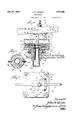
Figure l is a central vertical cross sectional view of a regulator embodying the present in=I vention; o
Fig. 2 is a top plan vievvvoi Fig. i;
Fig. 3 is a cross sectional View taken on the line 3-3 of lf'ig. l; and
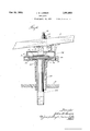
Fig. 4 is a central 'vertical cross sectional view partially in elevation showing another form of construction embodying the present ini/'enL1 tion.,
Referring more particularly to the drawings, the construction shown comprises a series of sunerposed exnansible diaphragm cells i, 2 3 having a volatile liquid container l depending therefrom and in communication therewith., Thel diaphragm cells are enclosed Within a case ing'cornprising an upper portion 5 and a base 5u which is connected. to a cup-like plug ineinm ber 6. The two portions 5 and 5u may be s^ cured together as by loolts 5l. The casing base 5a is provided With an opening 7' in the bottoni thereof through winch the volatile liquid con-- tainer i entends to loe positioned Within tire plug (i. A pivotally mounted lever S is actuated oy connecting means between the upper dian pli-vagin i and the lever il.
The cuililre plug u is screw threaded at 9 so that it may lie screwed into the top lo oi a hot :duid container, such as a hot Water boiler, with a portion of the plug extending within the hot :duid container. The plug 6 is formed with a Wrench engaging portion il adjacent the ,upper end so that the plug may he easily threaded into the top of the nnot uid container. The Wrench engaging 'portion il is provided with an annular channel i2.
The lower portion 5o oi the casing is oro-l vided With a depending annular portion i3 which is adapted to nt over the Wrench engaging por tion il and he rotatable thereabout. Securing rneans, such as the screw plugs la, are threaded into the annular 'portion i3 and register with tio anular channel l2. Ey this ineens, the may siviveled about the plug 6 and c in any desired position by the screw plugs when the latter is tightened to engage sides of the annular channel i2. A lifting post 'caving a hase portion li@ adapted to rest 1 central portion ci the diaphragm ds up through the opening i7 in the topo casing, the upper end o the lifting post l5 hein. jore'iera'oly loiiurcated. A lever support comprising a lease and a securing inernoer i9 having an aperture 20 through which the lever 8 is slidably inserted, is pivoted at one end of the base 18 to the upper end of the pivot post 15 by means of a pivot 21 extending through the bifurcated portions of the lifting post 15 and the downwardly extending base portion 22. Two downwardly extending side portions 23 adjacent the other end of the lever supporting member 18 are pivotally connected by means of the pivot 24 to the supporting members 25 extending upwardly from the top of the casing portion 5.
A screw bolt 26 is threaded through the top of the lever securing member 19 and when tightened engages the top of the lever 8 to prevent longitudinal movement thereof and to hold it in the desired position. The ends of the lever 8 may be operatively connected to the draft door and the check damper so that when one end of the lever is raised by the action of the lifting post 15 the draft door will be closed after which the check draft will be opened.
A quantity of volatile liquid is placed in the volatile liquid container 4, as shown at 27. As the lower end of the plug 6 extends within the hot fluid container, the same will be heated as the temperature of the fluid in the hot fluid container rises, The heat absorbed by the plug 6 is transferred to the volatile liquid container 4 and volatilizes the liquid therein forming a vapor in the volatile liquid container and in vvthe interior of the expansible diaphragms. As the temperature increases more of the liquid is volatilized and the pressure in the volatile liquid container and the diaphragm cells increases therewith. When all the liquid has been volatilized the increase in temperature thereafter does not produce the same increase in pressure as would occur before all the liquid was Volatilized but follows the laws of expansion of gases. Therefore, only sufficient liquid is placed in the container 4 so that the pressure produced by the volatilization due to the increase in temperature will not be great enough to burst the diaphragms in the use for which the device is intended.
As a safety precaution it has been found desirable to put in only enough volatile liquid so that it will all be transformed into vapor at approximately 212 Fahrenheit. As this device is primarily designed for use in hot water furnaces and hot water heaters, a temperature of 212 F. is as high as the temperature of the water should ever be heated. However, the amount of liquid in the container 4 may be varied according to the use to which the regulator is to be put. In order to adjust the regulator, slidable weights are placed on the lever 8 on each side of the pivot 24 and these may be adjusted so that the lever will be tilted about the pivot 24 at any particular temperature desired. A filler 27a, such as graphite, may be inserted between the volatile liquid container 4 and the plug 6 to insure a good and uniform conductivity of heat from the hot uid in the heater to the volatile liquid in the container. This, however, is not necessary for a proper operation of the regulator.
The construction shown in Fig. 4 is substantially the same as that shown in Figs, 1, 2 and 3 except that the tubular member 28 is open at the bottom so that the volatile liquid container 29 may extend directly within the hot fluid container. In this form, in order to prevent the escape of hot vapor and heat up through the tubular member 28 between the sides thereof and the volatile liquid container 29, an annular plug 30 having the outer face threaded, is secured to the volatile liquid container 29 adjacent the upper end thereof by any desirablemeans such as a sweated joint to form a tight connection.
'I'he plug 30 is threaded into the upper end of the tubular portion of the plug 28 with the annular ange 31 fitting into an annular groove 32 in the tubular member 28. In this form, the bottom 33 of the casing 34 is formed integrally with the tubular member 28 with screws 35 holding the casing 34 to the bottom 33.
A new and improved type of diaphragm cell is employed in the various forms of regulators within th scope of this invention. Each of the cells 1, 2 and 3, is formed with an upper portion 35a and a lower portion 36, the outer edges of the portions being tightly secured together and rolled under as shown in Fig. l to insure an absolutely tight jointure. The lower portion 36 is given a comparatively small upward slope toward the outer edges and is made of comparatively rigid material, the contour of which will remain practically unaffected by any change of pressure in the cells. Due to the material used in the constructionof the lower portion 36, and the slope thereof, all of the liquid in the cells will drain down toward the center and from thence into the volatile liquid container depending therefrom. The upper portion 35 of the cells is formed of comparatively flexible material which is corrugated or the like so that when the pressure in the cell fluctuates, the upper portion 35 will rise and fall, thereby actuating the operating arm 8.
The lowermost cell, of which any number may be employed, is formed with a center aperture in the bottom, which is of substantially the same size as the volatile liquid container which depends therefrom. The uppermost cell is formed with a solid upper surface and a perforated lower surface, while the'intermediate cells all have centrally located apertures in both surfaces so that all the cells may be communicatingly secured together as by means of eyelets 3'?. Thus the vapor formed by the volatile liquid in the container creates an equal pressure in all the cells.
While I have' shown and described but two embodiments of this invention, it will be apparent to those skilled in the art that various modifications may be made without departing from the spirit and scope of this invention and, therefore, I wish to be limited only by the scope of the prior art and the appended claims.
I claim:
1. A regulator construction comprising a series of superposed expansible diaphragm cells, a container for a volatile liquid depending from said cells and in communication therewith and of smaller diameter than said cells, a cup-like well for receiving said depending container having provisions for connection with the wall of a hot fluid container so that a portion of the volatile liquid container will be within the hot fluid container, and a housing for the diaphragm cells having an opening in its bottom of smaller diameter than said cells through which said volatile liquid container extends, said housing having a swivel connection with said cup-like well.
2. A regulator construction comprising a series of superposed expansible diaphragm cells, a container for a Volatile liquid depending from said cells and in communication therewith and of smaller diameter than said cells, a cup-like well for receiving said depending container having provision for connection with the wall of a hot uid container, and conducting filler material in said cup-like well between the sides thereof and the volatile liquid container, whereby there results a uniform conductivity of heat from the hot fluid in the hot fluid container to the volatile liquid.
3. A regulator construction comprising a series of superposed expansible diaphragm cells, a container for a volatile liquid depending from said cells and in communication therewith and of smaller diameter than said cells, a cup-like well for receiving said depending container having provision for connection with the wall of a hot fluid container, and graphite in said cup-like well between the sides thereof and the volatile liquid container, whereby there results a uniform conductivity of heat from the hot uid in the hot fluid container to the volatile liquid.
4. A regulator construction comprising an expansible diaphragm cell, a container for a volatile liquid depending from said cell and in communication therewith and of smaller diameter than said cell, a tubular connecting and supporting member having provisions for connection with an opening in the wall of a hot uid container, a housing for said diaphragm cell carried by said tubular member, said volatile liquid container extending into said tubular supporting member and into said hot uid container, and
said tubular member having its lower end closed to prevent the hot fluid from entering said housing. l
5. A regulator construction comprising an expansible diaphragm cell, a container for a volatile liquid depending from said cell and in communication therewith and of smaller diameter than said cell, a tubular connecting and supporting member having provisions for connection with an opening in the wall of a hot Huid container, a housing for said diaphragm cell carried by said tubular member, said volatile liquid container extending into said tubular supporting member and into said hot uid container, said tubular member having its lower end closed to prevent the hot uid from entering said housing, and said housing having a swivel connection with said tubular member.
6. A regulator construction comprising a series of superposed communicating expansible, selfdraining diaphragm cells, each of said cells comprising a rigid funnel-like bottom portion and a flexible top portion, said top and bottom por- 'tions being secured together adjacent their periphery, and means for connecting the lower rigid bottom portion of one cell to the upper flexible top portion of the cell underneath and providing communication between said cells, the rigid bottom portion of one cell being so closely connected to the exible top portion of the cell underneath that said rigid portion engages said flexible portion throughout a substantial portion of its extent when the cells are collapsed.
JOHN M. LARSON.
Priority Applications (1)
| Application Number | Priority Date | Filing Date | Title |
|---|---|---|---|
| US529491A US1931663A (en) | 1931-04-11 | 1931-04-11 | Regulator |
Applications Claiming Priority (1)
| Application Number | Priority Date | Filing Date | Title |
|---|---|---|---|
| US529491A US1931663A (en) | 1931-04-11 | 1931-04-11 | Regulator |
Publications (1)
| Publication Number | Publication Date |
|---|---|
| US1931663A true US1931663A (en) | 1933-10-24 |
Family
ID=24110128
Family Applications (1)
| Application Number | Title | Priority Date | Filing Date |
|---|---|---|---|
| US529491A Expired - Lifetime US1931663A (en) | 1931-04-11 | 1931-04-11 | Regulator |
Country Status (1)
| Country | Link |
|---|---|
| US (1) | US1931663A (en) |
Cited By (4)
| Publication number | Priority date | Publication date | Assignee | Title |
|---|---|---|---|---|
| US2459378A (en) * | 1946-06-10 | 1949-01-18 | William W Hallinan | Variable-speed pulley |
| US2785861A (en) * | 1951-02-21 | 1957-03-19 | Standard Thomson Corp | Tank vent controlling mechanism |
| US2961827A (en) * | 1958-05-20 | 1960-11-29 | Cutler Hammer Inc | Electro-thermal device of the thrust actuator type |
| US4186653A (en) * | 1977-11-01 | 1980-02-05 | Ranco Incorporated | Bellows assembly and method of making the same |
-
1931
- 1931-04-11 US US529491A patent/US1931663A/en not_active Expired - Lifetime
Cited By (4)
| Publication number | Priority date | Publication date | Assignee | Title |
|---|---|---|---|---|
| US2459378A (en) * | 1946-06-10 | 1949-01-18 | William W Hallinan | Variable-speed pulley |
| US2785861A (en) * | 1951-02-21 | 1957-03-19 | Standard Thomson Corp | Tank vent controlling mechanism |
| US2961827A (en) * | 1958-05-20 | 1960-11-29 | Cutler Hammer Inc | Electro-thermal device of the thrust actuator type |
| US4186653A (en) * | 1977-11-01 | 1980-02-05 | Ranco Incorporated | Bellows assembly and method of making the same |
Similar Documents
| Publication | Publication Date | Title |
|---|---|---|
| US1931663A (en) | Regulator | |
| US1932666A (en) | Steam-heater regulator | |
| US1897398A (en) | Inverse valve control for liquid and gas separators | |
| US2026423A (en) | Constant temperature device | |
| US1941023A (en) | Combination relief valve | |
| US4145604A (en) | Automatically controlled electric steam cooking pan | |
| US2251086A (en) | Valve | |
| US1999962A (en) | Liquid heater | |
| US2098131A (en) | Overflow preventing device | |
| US1731624A (en) | Electrically-heated steam radiator | |
| US1792891A (en) | Temperature-controlled valve | |
| US1825776A (en) | Float-controlled valve | |
| US4295605A (en) | Steam traps | |
| US2230741A (en) | Tank filling means | |
| US1347689A (en) | Thermostatic control device | |
| US1157255A (en) | Thermostatic heater. | |
| US1733120A (en) | Single-pipe steam-heating system | |
| US2216246A (en) | Regulator | |
| US2170777A (en) | Hot water heating radiator | |
| US1818053A (en) | Duplex automatic air vent valve | |
| US1637489A (en) | Breather valve | |
| US1425189A (en) | Thermostatically-controlled valve | |
| US509625A (en) | Temperature-regulator | |
| US989128A (en) | Damper-regulator. | |
| JPS59103087A (en) | Pressure safety valve device |