US1925462A - Dry cleaning machine - Google Patents
Dry cleaning machine Download PDFInfo
- Publication number
- US1925462A US1925462A US472970A US47297030A US1925462A US 1925462 A US1925462 A US 1925462A US 472970 A US472970 A US 472970A US 47297030 A US47297030 A US 47297030A US 1925462 A US1925462 A US 1925462A
- Authority
- US
- United States
- Prior art keywords
- basket
- fluid
- motor
- tub
- machine
- Prior art date
- Legal status (The legal status is an assumption and is not a legal conclusion. Google has not performed a legal analysis and makes no representation as to the accuracy of the status listed.)
- Expired - Lifetime
Links
- 238000005108 dry cleaning Methods 0.000 title description 7
- 239000012530 fluid Substances 0.000 description 47
- 238000004140 cleaning Methods 0.000 description 30
- 239000000463 material Substances 0.000 description 13
- 238000005406 washing Methods 0.000 description 8
- 239000006096 absorbing agent Substances 0.000 description 7
- 238000010981 drying operation Methods 0.000 description 6
- 238000010438 heat treatment Methods 0.000 description 6
- 230000002745 absorbent Effects 0.000 description 5
- 239000002250 absorbent Substances 0.000 description 5
- 238000001035 drying Methods 0.000 description 5
- 238000000034 method Methods 0.000 description 5
- VYPSYNLAJGMNEJ-UHFFFAOYSA-N Silicium dioxide Chemical compound O=[Si]=O VYPSYNLAJGMNEJ-UHFFFAOYSA-N 0.000 description 3
- 238000004821 distillation Methods 0.000 description 3
- 239000004519 grease Substances 0.000 description 3
- 230000007246 mechanism Effects 0.000 description 3
- 239000002184 metal Substances 0.000 description 3
- 230000001105 regulatory effect Effects 0.000 description 3
- 239000007787 solid Substances 0.000 description 3
- 238000009833 condensation Methods 0.000 description 2
- 230000005494 condensation Effects 0.000 description 2
- 239000004020 conductor Substances 0.000 description 2
- 238000001816 cooling Methods 0.000 description 2
- 239000000945 filler Substances 0.000 description 2
- 230000000717 retained effect Effects 0.000 description 2
- 239000000741 silica gel Substances 0.000 description 2
- 229910002027 silica gel Inorganic materials 0.000 description 2
- XLYOFNOQVPJJNP-UHFFFAOYSA-N water Substances O XLYOFNOQVPJJNP-UHFFFAOYSA-N 0.000 description 2
- 206010002383 Angina Pectoris Diseases 0.000 description 1
- 241000239290 Araneae Species 0.000 description 1
- 101100313164 Caenorhabditis elegans sea-1 gene Proteins 0.000 description 1
- 101100536354 Drosophila melanogaster tant gene Proteins 0.000 description 1
- 238000010521 absorption reaction Methods 0.000 description 1
- 238000009825 accumulation Methods 0.000 description 1
- 230000009471 action Effects 0.000 description 1
- 230000015572 biosynthetic process Effects 0.000 description 1
- 239000000498 cooling water Substances 0.000 description 1
- 238000007599 discharging Methods 0.000 description 1
- 238000005485 electric heating Methods 0.000 description 1
- 238000001914 filtration Methods 0.000 description 1
- 239000011521 glass Substances 0.000 description 1
- 230000005484 gravity Effects 0.000 description 1
- 238000012986 modification Methods 0.000 description 1
- 230000004048 modification Effects 0.000 description 1
- 238000012856 packing Methods 0.000 description 1
- 239000002245 particle Substances 0.000 description 1
- 238000005086 pumping Methods 0.000 description 1
- 230000000979 retarding effect Effects 0.000 description 1
- 239000004576 sand Substances 0.000 description 1
- 230000007480 spreading Effects 0.000 description 1
- 239000000126 substance Substances 0.000 description 1
- ZOKXUAHZSKEQSS-UHFFFAOYSA-N tribufos Chemical compound CCCCSP(=O)(SCCCC)SCCCC ZOKXUAHZSKEQSS-UHFFFAOYSA-N 0.000 description 1
Images


Classifications
-
- D—TEXTILES; PAPER
- D06—TREATMENT OF TEXTILES OR THE LIKE; LAUNDERING; FLEXIBLE MATERIALS NOT OTHERWISE PROVIDED FOR
- D06F—LAUNDERING, DRYING, IRONING, PRESSING OR FOLDING TEXTILE ARTICLES
- D06F43/00—Dry-cleaning apparatus or methods using volatile solvents
- D06F43/02—Dry-cleaning apparatus or methods using volatile solvents having one rotary cleaning receptacle only
Definitions
- An important object of the invention isto pro vide an improved form of basket for containing the articles to be cleaned, the basket being frustaconical with its sides inclined inwardly to a comparatively large degreen in order that, when the basket is rotated, the contents will be moved along the inclined sides and upwardly to fall back by gravity toward the bottom of the basket, there by causing the basket contents to be agitated and kept open and separated for the ready application thereto of cleaning fluid and whereby to prevent packing of the contents into compact form against the basket side.
- Another important object islto provide a. basket which is hung or suspended on an axial support with the load below the point of support, in order to assure more balance and less vibratory travel of the basket.
- a further object is to provide for more thorough and eilicient cleaning by rotating the basket at .comparatively slow speed While the contents are moved up and down during rotation of the basket and application of cleaning fluid thereto, the speed of the basket being just suflicient to cause the inclined sides thereof to eilect the up and down movement of the basket contents.
- a still further object is to utilize the pressure of the cleaning fluid delivered to the basket for driving a fluid motor to control the slow rotation of the basket during the washing operation of the contents and to provide an independent motor for rotating the basket at higher speed to cause drying of the Washed contents by centrifugal vforce.
- Still another object of ⁇ the invention is to provide improved means for withdrawing from the tub the vapors generated when the basket is rapidly7 rotated during a drying operation and to pass such vapors through condensing means from which the condensate is returned yto a supply tank for the machine.
- a further object is to provide simple, compact means in the form of an absorption device for receiving and storing the vapors of several drying operations oi the machine, together with means for driving the accumulated vapors from the device and condensing them for return to the supply tank for the machine.
- Another object is to provide means for heating the'used cleaning uid in the supply tank to a distilling temperature'and utilizing the vapor condensing means for the machine to condense such vapors of distillation and to deliver the condensate for reuse in the machine.
- a further object is to provide a machine which l is of simple, compact and economical construe# d@ tion, which is readily portable and which utilizes the cleaning fluid without permitting escape ci any of the vapors thereof into the open and which condenses the generated vapors and re turns them to the supply tank without any ma-m terial loss of cleaning uid.
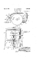
- Figure 1 is a front elevational view of the machine with the tub and spinner basket in vertical diametrical section;
- Figure 2 is a plan view of the machine
- Figure 3 is a side elevation
- Figure 4 is an enlarged section of the tub and I associated parts, showing the fluid circulating system
- Figure 5 is a view, partly in section, of the absorber and condenser elements and connections.
- the machine comprises a tub 10 shown of cylin- Vdrical form and with a dished bottom 11.
- tub is secured near its upper end to the upper ends of legs 12, and the tub rests on a spider frame 13 supported by and between the legs.
- a supply tank 14 for cleaning fluid which may be supported upon the legs 12 by suitable fittings 15.
- the upper edge 16 of the tube is curled outwardly to receive a cover 17 which may have bent openings 18 controlled by a damper 19, and which preferably has a glazed sight opening 20.
- a sea1. ing gasket 21 may be interposed between the tub and the cover.
- the tub and cover may be enameled, or'they may be entirely of a suitable metal or lined by such metal in order to be protected against'chemical action by cleaning fluid. l. f* Secured to the'bottom 11 ofthe tub concentric u. f
- a hub 22 therewith is a hub 22, and secured to the hub and extending vertically upwardly therethrough is a tube 23.
- a shaft 26 Aligned axially within the tube by upper and lower bushings 24 and 25 secured to the tube is a shaft 26.
- Concentric with the shaft is a spinner basket 2'7 of sheet metal and of truste-conical shape and with a .dished bottom 28. The bottom is deflected upwardly at its axis to Within a short distance of the top of the basket to form a frusto-conical support or hub 29 for the basket.
- the shaft extends through the top wall of this hub, and a collar 30, keyed to the 11 mavk shaft, is secured to the top wall of the hub in any suitable manner, so that the basket will be secured to the shaft to rotate therewith.
- basket is curled around or beaded to increase the rim strength and to afford a smooth edge.
- a bracket 34 secured to he machine framework at one side thereof, is ounted an electric drive motor 35 whose shaft 36 is vertical, the shaft being connected at its upper end to the rotor member of a blower or suction fan 37.
- a fluid pump 38 is secured in any suitable manner to the machine frame in axial alignment with the motor, the rotor of the pump being secured on a shaft 39.
- the shaft 36 receives a hub t0 with a belt pulleyfll thereon connected by a suitable belt 42 with the sheave t3 secured to .the lower end of the shaft 26 connected with the spinner basket.
- Suitable clutch mechanism t3 is associated with the shafts 36 and 39 and is controllable by a lever 44 to connect the driving motor with the pulley hub 40, or to connect the and the drive pulley will be ⁇ disconnected fromv the motor drive shaft.
- the inlet of the pump 38 is connected by a pipe 45 with the supply tank 14 near the bottom thereof, and the flow is controlled by a valve 46.
- the pump outlet is connected by a pipe 47 with a filter structure F comprising the outer casing 48 and the'inner frame or basket 49 for containing suitable filtering material 50, the basket being perforated.
- the pipe t7 extends upwardly through the bottom of the outer casing t8 and discharges into the bottom of the filter basket.
- a pipe 51 extends through the side of the tub (Fig. d) vand connects with the tangential inlet of a turbine structure 52 which is mounted just .above the spinner basket and has its rotor 53 connected with the upper end of the basket driving shaft 26.
- the pipe 51 may serve to hold the turbine frame against rotation, and the outlet 54 of the turbine directs the discharged cleaning .fluid downwardly into the basket into contact with clothes in the basket to be cleaned.
- the pressure of the iluiddischarged into the turbine by the pump will revolve the turbine and, conse-l quently, rotate the spinner basket, such rotation. .being at a comparatively low speed.
- the fluid discharge from the turbine is directed against the .clothes within the basket.
- Surplus cleaning fluid in the tub will return to the supply tank lil through a pipe 55 controlled by a valve 56.
- the basket with the clothes therein is rst rotatedA by the fluid motor turbine s-o that the fluid dieg charged from the turbine may thorolwhly soak in and lter through the clothes to carry away dirt, grease. etc., and then, after 'the fluid has been drained from. the tubpthe electric motor is connected to rotate the basket at a very much higher speed so as to extract the cleaning Vduid incassa by centrifugal force from the clothes to cause drying thereof. During such drying operation, the discharged fluid will be more or less vaporized, and I provide improved means for drawing such vapor out of the tub, condensing the same, and returning the condensate to the supply tank 14.
- the drawing orf of the vapor is accomplished by the blower or fan 37, which, as clearly shown in Figure 1, has its inlet connected by a duct 57 with the interior of the tub, the inlet of the duct being covered by a baffle frame 58 having the y screen 59 through which the vapor must pass before reaching the blower, the screen serving to filter out any solid .matter which might be carried by the vapor.
- the duct 57 is also provided with a flow-controlling valve 60.
- the cover 17 will ce in secure, tight-tting position on the tub.
- the vent openings 18 in the cover may be suitably regulated by the damper 19.
- the outlet of the suction fan or blower 37 is connected by a duct 61 with the bottom of a vapor retaining or absorbing device A.
- This device comprises the cy ⁇ lindrical tank 62, through the bottom of which the pipe 61 extends.
- a pipe 63 leads from the top of the tank to the upper end of the condensing coil 64 within the shell 65 of the condenser structure C, the lower end of the coil being connected with a return pipe 66. Cooling water enters the condenser shell at the bottom through a pipe 67 and flows out from the top through a pipe 63.
- sorne absorbent material 7l such as silica gel, such material being particularly ehestive in retarding the flow of and absorbing vapors of cleaning uids used in machines of this type.
- thevalve 60 in the blower inlet duct is opened, and the drawn out vapors will be discharged into the absorber structure A, where they will be in greater part retained and held by the absorbent material.
- Oridces 77 are provided in the Venturi tube I through the pipe 68 and through the tube, the suction created at the orifices is communicated to the chambers and 72, and any uncondensed vapors which would tend to follow the-condensate back to the tank 14 will be drawn out of the condensate circuit and carried with the discharged water from the condenser to the sewer,
- heating means 78 which may be a steam jacket, hot water or oil jacket,an electric coil, or other suitable means for supplying a controllable temperature.
- the absorber is then heated and the accumulated vapor in the absorbent material will be driven therefrom and will flowY through the condenser C to be condensed.
- the rate of heating is such that the rate of flow ofthe vapor will be proportionate to the size and capacity of the con denser, so that the condenser can efficiently per-v form the condensing operation with a minimum loss.
- the condensate from these vapors is returned to the supply tank le.
- the cover 17 is removed and the clothes or other articles to be cleaned are placed within the spinner basket 27.
- the clutch lever 44 is then shifted (Fig. 1) to connect only the pump with the electric motor, whereupon fluid is drawn from the supply tank 14 and delivered under pressure through the pipe 51 to the turbine 52, so that the basket will be rotated.
- the fluid discharged from the turbine will be projected against the'basket contents and will percolate and flow therethrough, and the return valve 56 may be closed for a while until the fluid rises to a desired level in the basket, for example, to a level just above the corner bend of the basket,
- the valve 56 is adjusted so that this level will be maintained during the washing operation.
- the contents will be more or less agitated and thrown outwardly by centrifugal force and solid particles, dirt, dissolved matter and other loose matter will drop through the basket perforations and will flow with the fluid back into the tank 14 and will settle in a sump 79 provided in the tank.
- valve 56 is rst opened wide to drain out the fluid from the tub, and then the clutch is shifted to disconnect the pump from the motor and to connect the drive pulley 41 with the motor so that, through the belt 42, the basket will be rotated at a comparatively high speed in order that all the fluid within the clothes will be extracted therefrom by centrifugal force, the extracted fluid flowing back' ⁇ to the supply tank.L
- valve 60 having been opened, the vapors generated during the .drying voperations.v are' carried offto the absorber device and to the condenser, as has already been explained, Vand the vapors are prevented from entering the room' -in which the machine is being operated and are practically all collected and condensed and returned to the supply tank. After the clothes have been thoroughly dried, the cover is removedv from the tub and the clothes are withdrawn from the basket.
- the basket being supported at the top, i. e., being suspended or hung from the top of the driving shaft 26, will be more balanced in its operation and will not unduly strain the shaft.
- Applicants method and procedure for washing and cleaning has been found to be morepractlcal and efficient than ⁇ prior methods.
- the prior methods have usually been to spin the basketat ⁇ comparatively high speed during the discharge of cleaning fluid against the basket contents. With such high speed, the contents are compressed up against the sides of the-basket into'such compact form that any material, such as grease, which has been dissolved from one part of the clothes will be carried by centrifugal force to be spread throughout the clothes. In other words, the cleaning fluid is hampered and prevented from efficient passage through the material of the clothes to properly dissolve and remove therefrom the matter to be cleaned away.- In applicants procedure, the basket is run at comparatively low speed.
- the clothes are thus gradually moved around in the basket without being tightly folded y and compacted together, and the cleaning fluid can then percolate freely therethrough and carry off the dissolved foreign matter and prevent spreading of such dissolved matter to other parts of the clothes.
- the valve e6 By adjusting the valve e6, the volume of pressure of the fluid delivered to the turbine can be regulated and the speed of the basket thereby adjusted.
- I provide for distilling the fluid by heating it and driving the vapor through the condenser C for condensation.
- I provide suitable heating means, as, for example, an electric heating pad 80, and I provide the outlet pipe 8l from the top of the tank to the condenser.
- I provide a valve 82 which is kept closed when the machine is operated for washing and drying but which is opened for the distillation of the tank contents.
- I insert a valve 83 which is opened for the washing and drying operation of the machine but which is closed when the tank contents are to be distilled.
- a pipe 84 extends from the outlet end of the condenser coil to the tub 10 a distance above the bottom thereof, and' this pipe includes a valve 85 which is opened only when the tank contents are to be distilled.
- valve 86 is included in the condensate return pipe When the tank contents are now heated, the
- distillate will flow through the pipe 81 and valve 82 directly to the top of the condenser coil 64 and the vapor will travel through the coil to be condensed,
- the tank 14 may be cleaned by withdrawing the plug 87 at the sump 79, and the accumulated solid matter, grease, etc. may be cleaned out of the tank.
- the valve 56 is opened and the cleaned condensate is returned from the tub to the tank ready for further operation of the machine.
- the tank is provided with a filler opening 88 through 1go d Gil which additional uid may be nlle'd in.
- a gauge glass 89 is also provided for indicating the level of the fluid in the'tank.
- the lter structure F may also be cleaned. As shown, the ller material basket 49 is suspended from the cover 48 of the filter frame and, by raising the cover, the ltcr cage may be withdrawn and the filler material removed and fresh ller material inserted.
- the heating of the silica gel or other absorbent material in the absorber structure A besides driving 0E the accumulated vapors, also revivie's the absorbent material.
- I thus provide a simple, efficient and readily transportable machine by which clothes or other articles may be einciently and thoroughly cleaned and rapidly dried, and where, during operation of the machine, the vapors are Withdrawn, condensed and returned to the fluid supply tank, together with a simple arrangement for distilling of the tank contents', cleaning of the supply tank and restoring thereto of the distilled condensate in clean form. Loss of fluid, therefore, is reduced to a minimum, and the same uid can be used over and over again for eincient Washing.
- a dry cleaning machine the combination of a tub, a clothesereceiving basket mounted in said tube for rotation therein, a motor and means for connecting it to drive said basket at comparatively high speed, a pump connected to be driven by said motor for supplying cleaning fluid to the basket, a turbine connected with said basket and connected to receive iluid'under pressure from said pump, and means for disconnecting said motor from said basket and for connecting the motor with said pump to cause said basket to be rotated at lower speed by said turbine.
- a dry cleaning machine the combination of a tub, a vertical drive shaft in said tub, a clothes-receiving basket suspended on said shaft for rotation therewith, a fluid motor on said shaft, an electric motor, fluid supply means, a pump connected with said uid motor and said supply means, means for connecting said electric motor with said driving shaft to cause rotation of said basket at comparatively high speed, and means for disconnecting said electric motor from said shaft and connecting it with said pump, whereby the fluid under pressure from said pump will operate said uid motor to cause rotation of said basket at reduced speed.
- a cleaning machine the combination of a tub, a spinner basket within said tub for receiving articles to be cleaned, a source of cleaning fluid, a iiuid motor connected with said basket, a conductor connecting said source with said motor, a pump in said conductor for forcing iiuid therethrough under pressure to said uid motor, a main driving motor having connection with said pump to drive said pump to operate said fluid motor to cause rotation of said basket thereby, means directing the discharge from said Huid motor to the contents of said basket, and means for disconnecting said main driving motor from said pump and for connecting it for directly driving saidbasket.
- a cleaning machine the combination of a tub, a basket rotatable within said tub and adapted to receive articles to be cleaned, a fluid motor mounted on said basket, a pump for supplying cleaning fluid under pressure to said iiuid motor, said fluid motor discharging into said basket, a main driving motor having driving connection withsaid basket, and means for disconnecting said main driving motor from said basket and connecting it with said pump to drive said pump to deliver cleaning fluid under pressure for operation of said fluid motor and rotation of the basket thereby.
- a cleaning machine the combination of a tub, a basket rotatable within said tub for containing Varticles to be cleaned, a main driving motor having driving connection with said basket, a :duid motor having driving connection with said basket to drive said basket at a diiierent speed, a pump for delivering fluid under pressure to said duid motor for operation thereof, and means for disconnecting said main driving motor from said basket and for connecting it to drive said pps RUDOLPH E ROSEAUM.
Landscapes
- Engineering & Computer Science (AREA)
- Textile Engineering (AREA)
- Drying Of Solid Materials (AREA)
Description
Sept. 5, 1933. R. R. RosENBAuM DRY CLEANING MACHINE '5 Sheets-Sheet `1 Filed Aug. 4. y1930 nav mvm..
ooo
oonoooeo 00000 sono o non oaoooo co0 ooooo..o ooo ooooooo @i QN.
.//E DE Sept 5, 1933. R. R. RQSENBAUM 1,925,462
DY CLEANING MACHINE Filed Aug. 4. 1930 3 Sheets-Sheet 2 d @Jaln/2z.,
Sept. 5, 1933. R. R. ROSENBAUM DRY CLEANING MACHINE 3 Sheets-Sheet 3 Filed Aug. 4. 1930 Cil Patented Septe 5, E933 ,par CLEANING MACHINE Rudolph n. raocentam, chicago, n1. apprenne angina ai, 1930. sensi No. nacre v eine... (ci. ca -1s) ii/ly invention relates to dry cleaning machines, and particularly to that type in which a basket or holder isvrotated within a tub containing cieanu ing fluid.
An important object of the invention isto pro vide an improved form of basket for containing the articles to be cleaned, the basket being frustaconical with its sides inclined inwardly to a comparatively large degreen in order that, when the basket is rotated, the contents will be moved along the inclined sides and upwardly to fall back by gravity toward the bottom of the basket, there by causing the basket contents to be agitated and kept open and separated for the ready application thereto of cleaning fluid and whereby to prevent packing of the contents into compact form against the basket side.
Another important object islto provide a. basket which is hung or suspended on an axial support with the load below the point of support, in order to assure more balance and less vibratory travel of the basket.
A further object is to provide for more thorough and eilicient cleaning by rotating the basket at .comparatively slow speed While the contents are moved up and down during rotation of the basket and application of cleaning fluid thereto, the speed of the basket being just suflicient to cause the inclined sides thereof to eilect the up and down movement of the basket contents.
A still further object is to utilize the pressure of the cleaning fluid delivered to the basket for driving a fluid motor to control the slow rotation of the basket during the washing operation of the contents and to provide an independent motor for rotating the basket at higher speed to cause drying of the Washed contents by centrifugal vforce.
Still another object of `the invention is to provide improved means for withdrawing from the tub the vapors generated when the basket is rapidly7 rotated during a drying operation and to pass such vapors through condensing means from which the condensate is returned yto a supply tank for the machine.
A further object is to provide simple, compact means in the form of an absorption device for receiving and storing the vapors of several drying operations oi the machine, together with means for driving the accumulated vapors from the device and condensing them for return to the supply tank for the machine.
Another object is to provide means for heating the'used cleaning uid in the supply tank to a distilling temperature'and utilizing the vapor condensing means for the machine to condense such vapors of distillation and to deliver the condensate for reuse in the machine.
A further object is to provide a machine which l is of simple, compact and economical construe# d@ tion, which is readily portable and which utilizes the cleaning fluid without permitting escape ci any of the vapors thereof into the open and which condenses the generated vapors and re turns them to the supply tank without any ma-m terial loss of cleaning uid.
The above enumerated and other important features of the invention are incorporated in the structure disclosed on the drawings, in which drawings: f
Figure 1 is a front elevational view of the machine with the tub and spinner basket in vertical diametrical section;
Figure 2 is a plan view of the machine;
Figure 3 is a side elevation; 75
Figure 4 is an enlarged section of the tub and I associated parts, showing the fluid circulating system; and
Figure 5 is a view, partly in section, of the absorber and condenser elements and connections.
The machine comprises a tub 10 shown of cylin- Vdrical form and with a dished bottom 11. The
tub is secured near its upper end to the upper ends of legs 12, and the tub rests on a spider frame 13 supported by and between the legs. Below the tub is a. supply tank 14 for cleaning fluid, which may be supported upon the legs 12 by suitable fittings 15.
The upper edge 16 of the tube is curled outwardly to receive a cover 17 which may have bent openings 18 controlled by a damper 19, and which preferably has a glazed sight opening 20. A sea1. ing gasket 21 may be interposed between the tub and the cover. The tub and cover may be enameled, or'they may be entirely of a suitable metal or lined by such metal in order to be protected against'chemical action by cleaning fluid. l. f* Secured to the'bottom 11 ofthe tub concentric u. f
therewith is a hub 22, and secured to the hub and extending vertically upwardly therethrough is a tube 23. Aligned axially within the tube by upper and lower bushings 24 and 25 secured to the tube is a shaft 26. Concentric with the shaft is a spinner basket 2'7 of sheet metal and of truste-conical shape and with a .dished bottom 28. The bottom is deflected upwardly at its axis to Within a short distance of the top of the basket to form a frusto-conical support or hub 29 for the basket. The shaft extends through the top wall of this hub, and a collar 30, keyed to the 11 mavk shaft, is secured to the top wall of the hub in any suitable manner, so that the basket will be secured to the shaft to rotate therewith. To
basket is curled around or beaded to increase the rim strength and to afford a smooth edge.
On a bracket 34, secured to he machine framework at one side thereof, is ounted an electric drive motor 35 whose shaft 36 is vertical, the shaft being connected at its upper end to the rotor member of a blower or suction fan 37. Below the motor a fluid pump 38 is secured in any suitable manner to the machine frame in axial alignment with the motor, the rotor of the pump being secured on a shaft 39. Directly below the motor the shaft 36 receives a hub t0 with a belt pulleyfll thereon connected by a suitable belt 42 with the sheave t3 secured to .the lower end of the shaft 26 connected with the spinner basket. Suitable clutch mechanism t3 is associated with the shafts 36 and 39 and is controllable by a lever 44 to connect the driving motor with the pulley hub 40, or to connect the and the drive pulley will be` disconnected fromv the motor drive shaft.
The inlet of the pump 38 is connected by a pipe 45 with the supply tank 14 near the bottom thereof, and the flow is controlled by a valve 46. The pump outlet is connected by a pipe 47 with a filter structure F comprising the outer casing 48 and the'inner frame or basket 49 for containing suitable filtering material 50, the basket being perforated. The pipe t7 extends upwardly through the bottom of the outer casing t8 and discharges into the bottom of the filter basket. From the upper end of the outer casing 48, a pipe 51 extends through the side of the tub (Fig. d) vand connects with the tangential inlet of a turbine structure 52 which is mounted just .above the spinner basket and has its rotor 53 connected with the upper end of the basket driving shaft 26. The pipe 51 may serve to hold the turbine frame against rotation, and the outlet 54 of the turbine directs the discharged cleaning .fluid downwardly into the basket into contact with clothes in the basket to be cleaned. The pressure of the iluiddischarged into the turbine by the pump will revolve the turbine and, conse-l quently, rotate the spinner basket, such rotation. .being at a comparatively low speed. During such rotation, the fluid discharge from the turbine is directed against the .clothes within the basket. Surplus cleaning fluid in the tub will return to the supply tank lil through a pipe 55 controlled by a valve 56.
fn the preferred operation of the machine, as will be more clearly explained hereinafter, the
basket with the clothes therein is rst rotatedA by the fluid motor turbine s-o that the fluid dieg charged from the turbine may thorolwhly soak in and lter through the clothes to carry away dirt, grease. etc., and then, after 'the fluid has been drained from. the tubpthe electric motor is connected to rotate the basket at a very much higher speed so as to extract the cleaning Vduid incassa by centrifugal force from the clothes to cause drying thereof. During such drying operation, the discharged fluid will be more or less vaporized, and I provide improved means for drawing such vapor out of the tub, condensing the same, and returning the condensate to the supply tank 14.
The drawing orf of the vapor is accomplished by the blower or fan 37, which, as clearly shown in Figure 1, has its inlet connected by a duct 57 with the interior of the tub, the inlet of the duct being covered by a baffle frame 58 having the y screen 59 through which the vapor must pass before reaching the blower, the screen serving to filter out any solid .matter which might be carried by the vapor. The duct 57 is also provided with a flow-controlling valve 60. Of course, while the machine is in operation, the cover 17 will ce in secure, tight-tting position on the tub. In orde to prevent the formation of a vacuum which might retard the drawing off of the vapor, the vent openings 18 in the cover may be suitably regulated by the damper 19.
The rapidly collected vapor could be condensed within the period of each drying operation of the machine provided the condenser were large enough. It is, however, impractical to use a large condenser, and I, therefore, provide means which will make the use of a small compact condenser possible and which will retain and accumulate the greater part of the vapors of the drying 0perations and which retained vapors may be subsequently driven off through the condenser and the condensate returned to the supply tank. Referring to Figures 1 and 5, the outlet of the suction fan or blower 37 is connected by a duct 61 with the bottom of a vapor retaining or absorbing device A. This device comprises the cy` lindrical tank 62, through the bottom of which the pipe 61 extends. A pipe 63 leads from the top of the tank to the upper end of the condensing coil 64 within the shell 65 of the condenser structure C, the lower end of the coil being connected with a return pipe 66. Cooling water enters the condenser shell at the bottom through a pipe 67 and flows out from the top through a pipe 63.
Within the tank. 62 of the absorber structure are upper and lower screens 69 and 70 between which is sorne absorbent material 7l., such as silica gel, such material being particularly ehestive in retarding the flow of and absorbing vapors of cleaning uids used in machines of this type.
'When it is desired to withdraw the vapor from the tub, thevalve 60 in the blower inlet duct is opened, and the drawn out vapors will be discharged into the absorber structure A, where they will be in greater part retained and held by the absorbent material. Tl'iose vapors that pass through reach the condenser yand iiow through the cooling coil thereof and are con= densed, and the condensate is eventually returned to the supphr tank it. To assist in dra the vapor into the cooling coil and also .to withdraw from the condensate any uncondensed vapor, I inm terpose the suction ober 72 in the condensate return circuit, the pipe66 extending partly into said chaniloer and a pipe 73 leading from the chamber back to the supply tant.: it. The suction within the chamber 72 is created of a 72. Oridces 77 are provided in the Venturi tube I through the pipe 68 and through the tube, the suction created at the orifices is communicated to the chambers and 72, and any uncondensed vapors which would tend to follow the-condensate back to the tank 14 will be drawn out of the condensate circuit and carried with the discharged water from the condenser to the sewer,
such uncondensed vapors being then prevented from polluting the atmosphere.
- For the absorber structure A, I provide heating means 78 which may be a steam jacket, hot water or oil jacket,an electric coil, or other suitable means for supplying a controllable temperature. After a period of use of the machine, the absorber is then heated and the accumulated vapor in the absorbent material will be driven therefrom and will flowY through the condenser C to be condensed. The rate of heating is such that the rate of flow ofthe vapor will be proportionate to the size and capacity of the con denser, so that the condenser can efficiently per-v form the condensing operation with a minimum loss. The condensate from these vapors is returned to the supply tank le.
Describing the operation of the machine for cleaning purposes, the cover 17 is removed and the clothes or other articles to be cleaned are placed within the spinner basket 27. The clutch lever 44 is then shifted (Fig. 1) to connect only the pump with the electric motor, whereupon fluid is drawn from the supply tank 14 and delivered under pressure through the pipe 51 to the turbine 52, so that the basket will be rotated. The fluid discharged from the turbine will be projected against the'basket contents and will percolate and flow therethrough, and the return valve 56 may be closed for a while until the fluid rises to a desired level in the basket, for example, to a level just above the corner bend of the basket,
. and then the valve 56 is adjusted so that this level will be maintained during the washing operation. During rotation of the basket, the contents will be more or less agitated and thrown outwardly by centrifugal force and solid particles, dirt, dissolved matter and other loose matter will drop through the basket perforations and will flow with the fluid back into the tank 14 and will settle in a sump 79 provided in the tank.
After a washing and cleaning operation of the clothes, the valve 56 is rst opened wide to drain out the fluid from the tub, and then the clutch is shifted to disconnect the pump from the motor and to connect the drive pulley 41 with the motor so that, through the belt 42, the basket will be rotated at a comparatively high speed in order that all the fluid within the clothes will be extracted therefrom by centrifugal force, the extracted fluid flowing back'` to the supply tank.L
The valve 60 having been opened, the vapors generated during the .drying voperations.v are' carried offto the absorber device and to the condenser, as has already been explained, Vand the vapors are prevented from entering the room' -in which the machine is being operated and are practically all collected and condensed and returned to the supply tank. After the clothes have been thoroughly dried, the cover is removedv from the tub and the clothes are withdrawn from the basket.
The basket being supported at the top, i. e., being suspended or hung from the top of the driving shaft 26, will be more balanced in its operation and will not unduly strain the shaft.
Applicants method and procedure for washing and cleaning has been found to be morepractlcal and efficient than \prior methods. The prior methods have usually been to spin the basketat` comparatively high speed during the discharge of cleaning fluid against the basket contents. With such high speed, the contents are compressed up against the sides of the-basket into'such compact form that any material, such as grease, which has been dissolved from one part of the clothes will be carried by centrifugal force to be spread throughout the clothes. In other words, the cleaning fluid is hampered and prevented from efficient passage through the material of the clothes to properly dissolve and remove therefrom the matter to be cleaned away.- In applicants procedure, the basket is run at comparatively low speed. The clothes are thus gradually moved around in the basket without being tightly folded y and compacted together, and the cleaning fluid can then percolate freely therethrough and carry off the dissolved foreign matter and prevent spreading of such dissolved matter to other parts of the clothes. By adjusting the valve e6, the volume of pressure of the fluid delivered to the turbine can be regulated and the speed of the basket thereby adjusted.
After a period of use of the machine, thefluid will become 'discolored, and the supply tank will have an accumulation of sand, dirt and other matter extracted from the clothes. I, therefore, provide for distilling the fluid by heating it and driving the vapor through the condenser C for condensation. Below the supply tank 14, I provide suitable heating means, as, for example, an electric heating pad 80, and I provide the outlet pipe 8l from the top of the tank to the condenser. In this pipe, I provide a valve 82 which is kept closed when the machine is operated for washing and drying but which is opened for the distillation of the tank contents. In the pipe 63, between the pipe 81 and the absorbing device A, I insert a valve 83 which is opened for the washing and drying operation of the machine but which is closed when the tank contents are to be distilled. f
For the distilling operation, a pipe 84 extends from the outlet end of the condenser coil to the tub 10 a distance above the bottom thereof, and' this pipe includes a valve 85 which is opened only when the tank contents are to be distilled. A
distillate will flow through the pipe 81 and valve 82 directly to the top of the condenser coil 64 and the vapor will travel through the coil to be condensed,
and-the condensate williflow through valve 85 and into the tub 10,the valvev 56 having previously been closed'. ."Iheheat for the tank is so regulated that the condenser Ck may take care of the condensation without material loss.
After the tank contents have all been distilled off from the tank 14 and the condensate has been collected in the tub 10, the tank 14 may be cleaned by withdrawing the plug 87 at the sump 79, and the accumulated solid matter, grease, etc. may be cleaned out of the tank. After the tank has been cleaned, the valve 56 is opened and the cleaned condensate is returned from the tub to the tank ready for further operation of the machine. The tank is provided with a filler opening 88 through 1go d Gil which additional uid may be nlle'd in. A gauge glass 89 is also provided for indicating the level of the fluid in the'tank. After the distillation process, the various valves are again adjusted for the Washing and drying operation of the machine.
After a period of use of the machine, the lter structure F may also be cleaned. As shown, the ller material basket 49 is suspended from the cover 48 of the filter frame and, by raising the cover, the ltcr cage may be withdrawn and the filler material removed and fresh ller material inserted.
The heating of the silica gel or other absorbent material in the absorber structure A, besides driving 0E the accumulated vapors, also revivie's the absorbent material.
I thus provide a simple, efficient and readily transportable machine by which clothes or other articles may be einciently and thoroughly cleaned and rapidly dried, and where, during operation of the machine, the vapors are Withdrawn, condensed and returned to the fluid supply tank, together with a simple arrangement for distilling of the tank contents', cleaning of the supply tank and restoring thereto of the distilled condensate in clean form. Loss of fluid, therefore, is reduced to a minimum, and the same uid can be used over and over again for eincient Washing.
Although I have shown an eiilcient and practical embodiment of the various features of my invention, I do not Wish to be limited thereto,'as changes and modifications in structure, arrangement and operation may be made Without departing from the scope and principles of my invention.
I claim as follows: i
1. In a dry cleaning machine, the combination of a tub, a clothesereceiving basket mounted in said tube for rotation therein, a motor and means for connecting it to drive said basket at comparatively high speed, a pump connected to be driven by said motor for supplying cleaning fluid to the basket, a turbine connected with said basket and connected to receive iluid'under pressure from said pump, and means for disconnecting said motor from said basket and for connecting the motor with said pump to cause said basket to be rotated at lower speed by said turbine.
2. In a dry cleaning machine, the combination of a tub, a clothes-containing basket mountm ed for rotation in said tub, an electric driving motor connected to drive said basket, a iiuid motor connected to drive said basket, a pump connected to be driven by said electric motor for pumping cleaning fluid through seid iuid `motor to the basket, and means for disconnect= incarica supply .means and said fluid motor, and clutch mechanism for connecting said electric motor with said basket to cause rotation of said basket at high speed and means whereby said clutch mechanism is operable to disconnect said basket from said electric motor and to eiect connection of said electric motor with said pump whereby uid under pressure will be delivered by said pump to said luidmotor and said fluid motor operatedto rotate said basket at lower' speed.
4. In a dry cleaning machine, the combination of a tub, a vertical drive shaft in said tub, a clothes-receiving basket suspended on said shaft for rotation therewith, a fluid motor on said shaft, an electric motor, fluid supply means, a pump connected with said uid motor and said supply means, means for connecting said electric motor with said driving shaft to cause rotation of said basket at comparatively high speed, and means for disconnecting said electric motor from said shaft and connecting it with said pump, whereby the fluid under pressure from said pump will operate said uid motor to cause rotation of said basket at reduced speed.
5. In a' cleaning machine, the combination of a tub, a spinner basket within said tub for receiving articles to be cleaned, a source of cleaning fluid, a iiuid motor connected with said basket, a conductor connecting said source with said motor, a pump in said conductor for forcing iiuid therethrough under pressure to said uid motor, a main driving motor having connection with said pump to drive said pump to operate said fluid motor to cause rotation of said basket thereby, means directing the discharge from said Huid motor to the contents of said basket, and means for disconnecting said main driving motor from said pump and for connecting it for directly driving saidbasket.
6. In a cleaning machine, the combination of a tub, a basket rotatable within said tub and adapted to receive articles to be cleaned, a fluid motor mounted on said basket, a pump for supplying cleaning fluid under pressure to said iiuid motor, said fluid motor discharging into said basket, a main driving motor having driving connection withsaid basket, and means for disconnecting said main driving motor from said basket and connecting it with said pump to drive said pump to deliver cleaning fluid under pressure for operation of said fluid motor and rotation of the basket thereby.
7. In a cleaning machine, the combination of a tub, a basket rotatable within said tub for containing Varticles to be cleaned, a main driving motor having driving connection with said basket, a :duid motor having driving connection with said basket to drive said basket at a diiierent speed, a pump for delivering fluid under pressure to said duid motor for operation thereof, and means for disconnecting said main driving motor from said basket and for connecting it to drive said pps RUDOLPH E ROSEAUM.
iss
Priority Applications (1)
| Application Number | Priority Date | Filing Date | Title |
|---|---|---|---|
| US472970A US1925462A (en) | 1930-08-04 | 1930-08-04 | Dry cleaning machine |
Applications Claiming Priority (1)
| Application Number | Priority Date | Filing Date | Title |
|---|---|---|---|
| US472970A US1925462A (en) | 1930-08-04 | 1930-08-04 | Dry cleaning machine |
Publications (1)
| Publication Number | Publication Date |
|---|---|
| US1925462A true US1925462A (en) | 1933-09-05 |
Family
ID=23877643
Family Applications (1)
| Application Number | Title | Priority Date | Filing Date |
|---|---|---|---|
| US472970A Expired - Lifetime US1925462A (en) | 1930-08-04 | 1930-08-04 | Dry cleaning machine |
Country Status (1)
| Country | Link |
|---|---|
| US (1) | US1925462A (en) |
Cited By (9)
| Publication number | Priority date | Publication date | Assignee | Title |
|---|---|---|---|---|
| US2566488A (en) * | 1945-04-28 | 1951-09-04 | Murray Corp | Combined fabric washing and drying unit |
| US2592596A (en) * | 1945-08-24 | 1952-04-15 | Wilbert L Pengelly | Jet action washing machine |
| US2745217A (en) * | 1953-05-05 | 1956-05-15 | Gold Richard Lucius | Machine for improving the keeping qualities of plants and restoring wilted plants to full freshness |
| US2818719A (en) * | 1952-05-19 | 1958-01-07 | Kermit R Cline | Combined washing and drying apparatus |
| US2939305A (en) * | 1956-12-05 | 1960-06-07 | Gen Motors Corp | Lint filter for washing machine |
| US3144759A (en) * | 1963-06-27 | 1964-08-18 | Gen Electric | Washing machine |
| US3192745A (en) * | 1962-10-29 | 1965-07-06 | Gen Electric | Automatic washing machine with means for drying small articles |
| US3538615A (en) * | 1967-03-23 | 1970-11-10 | Boewe Boehler & Weber Kg Masch | Drycleaning machine with adsorber |
| US5946945A (en) * | 1997-12-24 | 1999-09-07 | Kegler; Andrew | High pressure liquid/gas storage frame for a pressurized liquid cleaning apparatus |
-
1930
- 1930-08-04 US US472970A patent/US1925462A/en not_active Expired - Lifetime
Cited By (9)
| Publication number | Priority date | Publication date | Assignee | Title |
|---|---|---|---|---|
| US2566488A (en) * | 1945-04-28 | 1951-09-04 | Murray Corp | Combined fabric washing and drying unit |
| US2592596A (en) * | 1945-08-24 | 1952-04-15 | Wilbert L Pengelly | Jet action washing machine |
| US2818719A (en) * | 1952-05-19 | 1958-01-07 | Kermit R Cline | Combined washing and drying apparatus |
| US2745217A (en) * | 1953-05-05 | 1956-05-15 | Gold Richard Lucius | Machine for improving the keeping qualities of plants and restoring wilted plants to full freshness |
| US2939305A (en) * | 1956-12-05 | 1960-06-07 | Gen Motors Corp | Lint filter for washing machine |
| US3192745A (en) * | 1962-10-29 | 1965-07-06 | Gen Electric | Automatic washing machine with means for drying small articles |
| US3144759A (en) * | 1963-06-27 | 1964-08-18 | Gen Electric | Washing machine |
| US3538615A (en) * | 1967-03-23 | 1970-11-10 | Boewe Boehler & Weber Kg Masch | Drycleaning machine with adsorber |
| US5946945A (en) * | 1997-12-24 | 1999-09-07 | Kegler; Andrew | High pressure liquid/gas storage frame for a pressurized liquid cleaning apparatus |
Similar Documents
| Publication | Publication Date | Title |
|---|---|---|
| US2198412A (en) | Removal and recovery of solvent | |
| US3401052A (en) | Method and apparatus for waterproofing textiles | |
| US3161481A (en) | Fabric drying machine with timer control | |
| US3273256A (en) | Dry cleaning machine | |
| US1925462A (en) | Dry cleaning machine | |
| US2106589A (en) | Boiler drum | |
| US1775699A (en) | Dry-cleaning apparatus | |
| US2359138A (en) | Apparatus for cleaning materials | |
| US3246493A (en) | Dry cleaning apparatus | |
| US3388567A (en) | Dry cleaning apparatus | |
| US3163028A (en) | Automatic dry cleaning machine and combined fluid filter and vapor condenser | |
| US2660869A (en) | Dry cleaning apparatus | |
| US2344982A (en) | Method oe washing | |
| US2996809A (en) | Clothes dryer | |
| US3242589A (en) | Apparatus for reclaiming solvent from used filter cartridges | |
| US1869510A (en) | Washing machine | |
| US1899005A (en) | Combination washing machine and extractor | |
| US1802034A (en) | Apparatus for use in dry-cleaning operations | |
| US2053103A (en) | Dry cleaning apparatus | |
| US2738877A (en) | Combined oil purifier and water separator | |
| US3108464A (en) | Lint filtering and disposal arrangement for clothes cleaning machine | |
| US3249230A (en) | Reclamation of dry cleaning fluid | |
| US1463016A (en) | Washing machine | |
| US2041711A (en) | Apparatus for cleaning fabrics | |
| US2016552A (en) | Dry cleaning apparatus |