US1925299A - Water heater - Google Patents
Water heater Download PDFInfo
- Publication number
- US1925299A US1925299A US636058A US63605832A US1925299A US 1925299 A US1925299 A US 1925299A US 636058 A US636058 A US 636058A US 63605832 A US63605832 A US 63605832A US 1925299 A US1925299 A US 1925299A
- Authority
- US
- United States
- Prior art keywords
- water heater
- fire box
- jacket
- jackets
- casing
- Prior art date
- Legal status (The legal status is an assumption and is not a legal conclusion. Google has not performed a legal analysis and makes no representation as to the accuracy of the status listed.)
- Expired - Lifetime
Links
Images


Classifications
-
- F—MECHANICAL ENGINEERING; LIGHTING; HEATING; WEAPONS; BLASTING
- F24—HEATING; RANGES; VENTILATING
- F24H—FLUID HEATERS, e.g. WATER OR AIR HEATERS, HAVING HEAT-GENERATING MEANS, e.g. HEAT PUMPS, IN GENERAL
- F24H1/00—Water heaters, e.g. boilers, continuous-flow heaters or water-storage heaters
- F24H1/22—Water heaters other than continuous-flow or water-storage heaters, e.g. water heaters for central heating
- F24H1/38—Water heaters other than continuous-flow or water-storage heaters, e.g. water heaters for central heating with water contained in separate elements, e.g. radiator-type element
Definitions
- the present invention relates to new and useful improvements in water heaters, and has for some of its objects to provide in a manner as hereinafter set forth, a device of this character which will be comparatively simple in construction, strong, durable, highly efficient and reliable in use, compact, and which may be manufactured at low cost.
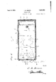
- Figure 1 is a top plan view, showing a water heater constructed in accordance with the pres- 'ent invention.
- Fig. 2 is a view in front elevation of the water showing the door swung to open position.
- Fig. 3 is a view in vertical longitudinal section through the water heater, taken substantially on the line 33 of Fig. 1.
- Fig. 4 is a view in horizontal section through the water heater taken substantially on the line 4-4 of Fig. 3 and looking downwardly, as indicated by the arrows.
- a fire box which is designated generally by the reference numeral 1, said fire box including a bottom 2, a front plate 3, a back plate 4, and side plates 5.
- a substantially U-shaped casing is mounted on the .fire box 1, said casing being designated by the reference numeral 6 and having a lining 7 of suitable material, preferably asbestos.
- a door frame 8 Rising from the front plate 3 of the fire box 1 is a door frame 8 having hingedly mounted thereon a door 9.
- a series of vertically spaced, horizontally disposed water jackets 10 which are substantially rectangular in plan.
- uppermost jacket 10 constitutes the top of the heater and is provided with a flange 11 which rests on top of the casing 6.
- the lowermost jacket 10 is disposed in the'fire box 1 and is secured therein, as at 12.
- the jackets 10 are provided with staggered flue passages 13 and the adjacent jackets are connected together and have communication with each other through couplings or nipples 14 which also are staggered and located adjacent the flue passages 13.
- Theadedly mounted in the forward end of each "-jacket 10 is a cleanout plug 15.
- a water pipe 16 is connected with the top of the uppermost section 10 and a pipe 1'? is connected with one side of the lowermost jacket 10 through the corresponding side wall 5 of the fire box 1.
- the reference numeral 19 designates, in broken lines, a burner of suitable construction which is mounted in the fire box 1 beneath the lowermost jacket 10.
- a fuel supply pipe 20 has branches passing through openings provided therefor in the front'plate 3 of the fire box 1 and connected to the burner 19.
- heat from the burner 19 acts directly on the lowermost jacket 10 and the products of combustion, then follows a substantially zig-zag course, and indicated by the arrows in Fig. 3 of the drawings, from the fire box through the flue passages 13 and between the jackets 10 to 75, the flue (not shown) which is connected to the neck 18.
- the water also travels in a substantially zig-zag course through the jackets 10 and the connections, or nipples 14 between the inlet and outlet pipes of the heater.
- a water heater comprising a fire box including a bottom and side and end walls, the front end wall being of less height than the other walls, a substantially U-shaped casing having its lower edges resting upon the upper edges of the side and rear end walls of the fire box, a door frame extending from the upper edge of the front end of the fire box to the top of the casing, a door hinged to said frame, said frame and door closing the front of the casing and the upper part of the front of the fire box, a plurality of vertically spaced water jackets horizontally arranged, with the lower one partly fitting in the top part of the fire box and secured thereto and the upper one of which is flanged at its top, with the flange engagtop jacket in communication with the last-men'- tioned passage, short nipples connecting the jackets together adjacent the flue passages, an outlet pipe connected with the top jacket and an inlet pipe connected with the lower jacket, said pipes being connected with the central portionsof said jackets.
Description
Sept. 5, 1933. J 3 BROWN 1,925,299
WATER HEATER Filed 001;. 5, 1952 4 Sheets-Sheet 1 Inventor /Illomcy Sept. 5, 1933. J. B. BROWN 1,925,299
WATER HEATER Filed Oct. 3, 1932 4 Sheets-Sheet 2 I A: ll a Q a;
IL: I J\ T fifi K. cl. k
;:T f T 6X Inventor K r]: B .Brown Sept. 5, 1933. J 3 OWN 1,925,299
- WATER HEATER Filed Oct. 3, 1932 4 Sheets-Sheet 3 Inventor Patented" Sept. 5, 1933 STATES PATENT OFFICE 1 Claim.
The present invention relates to new and useful improvements in water heaters, and has for some of its objects to provide in a manner as hereinafter set forth, a device of this character which will be comparatively simple in construction, strong, durable, highly efficient and reliable in use, compact, and which may be manufactured at low cost.
All of the foregoing and still further objects and advantages of the invention will become apparent from a study of the following specification, taken in connection with the accompanying drawings, wherein like characters of reference designate corresponding parts throughout the several views, and wherein:
Figure 1 is a top plan view, showing a water heater constructed in accordance with the pres- 'ent invention.
Fig. 2 is a view in front elevation of the water showing the door swung to open position.
Fig. 3 is a view in vertical longitudinal section through the water heater, taken substantially on the line 33 of Fig. 1.
Fig. 4 is a view in horizontal section through the water heater taken substantially on the line 4-4 of Fig. 3 and looking downwardly, as indicated by the arrows.
Referring now to the drawings wherein it will be seen that the embodiment of the present invention as illustrated, comprises a fire box which is designated generally by the reference numeral 1, said fire box including a bottom 2, a front plate 3, a back plate 4, and side plates 5.
A substantially U-shaped casing is mounted on the .fire box 1, said casing being designated by the reference numeral 6 and having a lining 7 of suitable material, preferably asbestos. Rising from the front plate 3 of the fire box 1 is a door frame 8 having hingedly mounted thereon a door 9.
Mounted in the casing 6 is a series of vertically spaced, horizontally disposed water jackets 10 which are substantially rectangular in plan. The
Rising from the forward end portion of uppermost jacket 10 and communicating with the flue passage 13 thereof is a neck 18 for connection with a flue. The reference numeral 19 designates, in broken lines, a burner of suitable construction which is mounted in the fire box 1 beneath the lowermost jacket 10. A fuel supply pipe 20 has branches passing through openings provided therefor in the front'plate 3 of the fire box 1 and connected to the burner 19.
In operation, heat from the burner 19 acts directly on the lowermost jacket 10 and the products of combustion, then follows a substantially zig-zag course, and indicated by the arrows in Fig. 3 of the drawings, from the fire box through the flue passages 13 and between the jackets 10 to 75, the flue (not shown) which is connected to the neck 18. The water also travels in a substantially zig-zag course through the jackets 10 and the connections, or nipples 14 between the inlet and outlet pipes of the heater.
As will be apparent, access to the jackets 10 and the interior of the casing 6 may be conveniently had through the medium of the swinging door 9.
It is believed that the many advantages of a water heater constructed in accordance with the present invention will be readily understood, and although the preferred embodiment of the invention is as illustrated and described, it is to be understood that changes in the details of construction, and in the combination and arrangement of parts may be resorted to which will fall within the scope of the invention as claimed.
Having thus described my invention, what I claim as new is:
A water heater comprising a fire box including a bottom and side and end walls, the front end wall being of less height than the other walls, a substantially U-shaped casing having its lower edges resting upon the upper edges of the side and rear end walls of the fire box, a door frame extending from the upper edge of the front end of the fire box to the top of the casing, a door hinged to said frame, said frame and door closing the front of the casing and the upper part of the front of the fire box, a plurality of vertically spaced water jackets horizontally arranged, with the lower one partly fitting in the top part of the fire box and secured thereto and the upper one of which is flanged at its top, with the flange engagtop jacket in communication with the last-men'- tioned passage, short nipples connecting the jackets together adjacent the flue passages, an outlet pipe connected with the top jacket and an inlet pipe connected with the lower jacket, said pipes being connected with the central portionsof said jackets.
JOHN B. BROWN.
Priority Applications (1)
| Application Number | Priority Date | Filing Date | Title |
|---|---|---|---|
| US636058A US1925299A (en) | 1932-10-03 | 1932-10-03 | Water heater |
Applications Claiming Priority (1)
| Application Number | Priority Date | Filing Date | Title |
|---|---|---|---|
| US636058A US1925299A (en) | 1932-10-03 | 1932-10-03 | Water heater |
Publications (1)
| Publication Number | Publication Date |
|---|---|
| US1925299A true US1925299A (en) | 1933-09-05 |
Family
ID=24550234
Family Applications (1)
| Application Number | Title | Priority Date | Filing Date |
|---|---|---|---|
| US636058A Expired - Lifetime US1925299A (en) | 1932-10-03 | 1932-10-03 | Water heater |
Country Status (1)
| Country | Link |
|---|---|
| US (1) | US1925299A (en) |
Cited By (3)
| Publication number | Priority date | Publication date | Assignee | Title |
|---|---|---|---|---|
| US2490693A (en) * | 1946-05-02 | 1949-12-06 | Thomas E Lennon | Steam or hot-water boiler |
| US2619955A (en) * | 1948-08-07 | 1952-12-02 | Affiliated Gas Equipment Inc | Flat tank water heater |
| US20100139578A1 (en) * | 2007-07-02 | 2010-06-10 | Jae Eun NOR | Boiler with flat horizontal tubes |
-
1932
- 1932-10-03 US US636058A patent/US1925299A/en not_active Expired - Lifetime
Cited By (3)
| Publication number | Priority date | Publication date | Assignee | Title |
|---|---|---|---|---|
| US2490693A (en) * | 1946-05-02 | 1949-12-06 | Thomas E Lennon | Steam or hot-water boiler |
| US2619955A (en) * | 1948-08-07 | 1952-12-02 | Affiliated Gas Equipment Inc | Flat tank water heater |
| US20100139578A1 (en) * | 2007-07-02 | 2010-06-10 | Jae Eun NOR | Boiler with flat horizontal tubes |
Similar Documents
| Publication | Publication Date | Title |
|---|---|---|
| US2299901A (en) | Hot air furnace | |
| US1925299A (en) | Water heater | |
| US2475481A (en) | Portable water still | |
| US1884634A (en) | Portable hot water heater | |
| US2382800A (en) | Forced draft heater | |
| US2128842A (en) | Hot water heater | |
| US1935852A (en) | Heater | |
| US1668125A (en) | Hot-air heating furnace | |
| US2038123A (en) | Boiler | |
| US2062033A (en) | Boiler | |
| US914085A (en) | Range. | |
| US1828319A (en) | Hot air heater | |
| US2115614A (en) | Boiler construction | |
| US1426642A (en) | Tubular hot-air furnace | |
| US268615A (en) | Heating-furnace | |
| US1822397A (en) | A coeporatiou | |
| US1629384A (en) | Gas heater | |
| US1604833A (en) | Hot-air furnace | |
| US2957473A (en) | Heater | |
| US1497123A (en) | Fireplace heater | |
| US660662A (en) | Stove. | |
| US1762540A (en) | Domestic baking oven | |
| US1679406A (en) | Combined boiler and heating device | |
| US1369069A (en) | Furnace | |
| US1942915A (en) | Boiler for hot water heating systems |