US1925259A - Dishwasher - Google Patents
Dishwasher Download PDFInfo
- Publication number
- US1925259A US1925259A US536130A US53613031A US1925259A US 1925259 A US1925259 A US 1925259A US 536130 A US536130 A US 536130A US 53613031 A US53613031 A US 53613031A US 1925259 A US1925259 A US 1925259A
- Authority
- US
- United States
- Prior art keywords
- tub
- wires
- compartments
- rack
- dishes
- Prior art date
- Legal status (The legal status is an assumption and is not a legal conclusion. Google has not performed a legal analysis and makes no representation as to the accuracy of the status listed.)
- Expired - Lifetime
Links
- 239000011521 glass Substances 0.000 description 14
- XLYOFNOQVPJJNP-UHFFFAOYSA-N water Substances O XLYOFNOQVPJJNP-UHFFFAOYSA-N 0.000 description 13
- 238000004851 dishwashing Methods 0.000 description 10
- 238000005406 washing Methods 0.000 description 6
- 238000013019 agitation Methods 0.000 description 2
- 238000005096 rolling process Methods 0.000 description 2
- 102000010029 Homer Scaffolding Proteins Human genes 0.000 description 1
- 108010077223 Homer Scaffolding Proteins Proteins 0.000 description 1
- 230000015572 biosynthetic process Effects 0.000 description 1
- 230000000694 effects Effects 0.000 description 1
- 239000004519 grease Substances 0.000 description 1
- 238000003780 insertion Methods 0.000 description 1
- 230000037431 insertion Effects 0.000 description 1
- 239000000463 material Substances 0.000 description 1
- 238000000034 method Methods 0.000 description 1
- 230000000284 resting effect Effects 0.000 description 1
Images

Classifications
-
- A—HUMAN NECESSITIES
- A47—FURNITURE; DOMESTIC ARTICLES OR APPLIANCES; COFFEE MILLS; SPICE MILLS; SUCTION CLEANERS IN GENERAL
- A47L—DOMESTIC WASHING OR CLEANING; SUCTION CLEANERS IN GENERAL
- A47L15/00—Washing or rinsing machines for crockery or tableware
- A47L15/02—Washing or rinsing machines for crockery or tableware with circulation and agitation of the cleaning liquid in the cleaning chamber containing a stationary basket
- A47L15/04—Washing or rinsing machines for crockery or tableware with circulation and agitation of the cleaning liquid in the cleaning chamber containing a stationary basket by reciprocating movement of the cleaning chamber
Definitions
- This invention relates to the art of dishwashing machines and has for one of its primary objects the provision of a washing tub which will effectively wash dishes contained therein by simple reciprocatory motion of the tub and wit.-- out the use of other moving parts within the tub.
- a primary object of the invention is to provide a surface or a plurality of surfaces within the tub which will induce a current of water to travel with some force between dishes placed thereover upon the reciprocation of the tub itself.
- a further important object of the invention resides in the particular unique method of positioning and retaining dishes within the tub and in the structure provided therefor.
- a further important object of the invention is to provide means for removably retaining cups and glasses within the tub at certain positions therein whereby the effect of the splashing water may be utilized to the best advantage in having the water flow within and over them.
- a further important object is to provide means which may be varied to hold glasses and cups of varying sizes.
- FIG. 1 is a fragmentary side elevation of a wash ing machine embodying our invention
- Fig. 2 a detail in fragmentary top plan View of the power driving mechanism
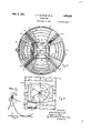
- FIG. 3 a fragmentary top plan view of the washing machine with the cover and cup and glass holder removed;
- Fig. 4 is a top plan View of the cup and glass holder
- baflies 14 here shown as four in number. These battles are positioned to have their outer ends against the inner side of the tub to extend radially therefrom toward but terminating at a distance from the center of the tub.
- Each of the baflies 14 has a concave surface on each side, which surfaces unite at the top edge of the bafiie and slope downwardly and outwardly therefrom to merge into the bottom of the tub 10.
- the upper edge of each of the baffles 14 slope downwardly somewhat from the wall of the tub 10 toward the center thereof.
- a'wire rack 15 which has a central rectangular portion and wings extending and flaring out therefrom into each of the spaces between adjacent bafiies 14.
- Each of the wings of this rack 15 has arcuate wires 16 spaced one from the other as means for positioning and holding therebetween dishes or plates 17, the distance between adjacent wires 16 and the side wires 18 of the wing being proportioned to permit the periphery of the dishes to rest against the side wires 13 so as to hold the dishes slightly above the bottom of the tub 10.
- This rack 15 is free to be removed from the tub 10 and normally rests therein by having the side wires 18 of each of the. wings rest upon the concave walls between the baffles 14.
- wires 21 The purpose of these wires 21 is to provide retaining and spacing means for holding dishes 1'7 in substantially-vertical and spaced apart positions, a wire 21 being placed between each of two adjacent dishes.
- the central part of the frame 19 which is here shown as being rectangular in shape holds a plurality of U-shaped wires 22 swingingly suspended between opposite sides of the frame.
- Dishes of any suitable size and shape may be held over the central portion of the rack 15 and spaced apart one from the other by means of these wires 22 which are yieldingly'sprung between the side members of the frame 19 to frictionally resist swinging but permitting motion upon sufficient pressure being applied thereto.
- a basket 23 is hung from one side of the frame 19 by the hooks 24.
- This basket 23 is preferably made of reticulated material such as woven wire and may be removed simply by pulling'the basket upwardly to disengage the hooks 24 from the frame 19.
- This basket 23 is provided to retain silverware including knives, forks, spoons and the like whereby such articles will be held in vertical positions.
- the battles 14 terminate at a substantial distance tub 10 and between the tops of the baiiies l4 and the top of the tub 14 we removably mount a rack 25 by positioning the downwardly extending legs 26 thereof to rest on the bafiles 14 at the outermost ends thereof.
- Each of the lower ends of the legs 26 is bifurcated to have the legs straddle the baffles, Fig. 5.
- the rack 25 is here shown as being rectangular in shape and supports centrally thereof a circular band 27 which has wires 28 extending radially thereof.
- a post 29 extends vertically and centrally of the band 27 and carries thereon the lower and upper butterfly wheels 30 and 31 respectively, each adjustable longitudinally of the post 29. Both wheels 30 and 31 have a number of wings or blades extending radially equal in number to the number of wires 28.
- cups 32 may be positioned on edge, one slightly telescoping the other radially around and over the band 27 to have the lower parts of the cups rest against the band 27 and the wires 28 and the inner parts of the lips of the cups between and against the blades of the wheels 30 and 31 whereby the cups will be nested around the band 27 closely spaced toward the post 29 and yet held apart sufiiciently to permit water to slop into the cup and outwardly therefrom over the outer surface of the next adjacent cup.
- each of these wires 63 and 33 carries a clip 34 at each end directed inwardly toward each other under which. the lip of a glass 35 may be inserted to have the bottom end of the glass rest upon any one of the steps of the wires as may be presented thereunder depending upon the length and diameter of the glass.
- the outer ring of the rack 25 prevents the glass from rolling outwardly and inner wires 36 and 37 curving arcuately around the band 27 prevent the glass from rolling inwardly therebeyond.
- each of the wires 38 and 39 being provided with clips 34 and inclined steps 40 at their opposite ends.
- the wires 38 and 39 are spaced inwardly from the edge wires of the rack 25 to have arcuate wires 41 and 42 between them and the band 27 so as to provide supporting means on each side of the glass holding wires.
- a motor 44 which has a worm 45 on the shaft thereof and held in permanent mesh with the worm wheel 46.
- a connecting link 47 is pivotally mounted by one end on the upper face of the wheel 46 and by the other end to the underside of the plate 11 whereby 85 rotation of the wheel 46 will cause the tub 10 to be reciprocated.
- the shaft of the motor 44 extends loosely through the worm 45 to carry a shiftable collar 48 thereon in such a manner that while the collar may be shifted longitudinally along the shaft, the collar will be rotated thereby.
- a flange 49 which is fixed on the end of a flexible shaft 50 which extends through a suitable housing 51 to revolve a brush 52 carried on the outer end of the shaft.
- a handle 53 is provided to selectively shift the collar 48 against either a flange 54 integral with the worm 45 or against the flange 49.
- a hole is provided centrally through the bottom of the tub 1D to provide a discharge outlet from the tub into the bore of the spindle l2 and a hose 55 is fixed to the bottom of the spindle and carried up around the side of the tub 10 to have the outer end thereof removably held by the bracket 56 near the top of the tub.
- a suitable hook 57 is provided on the side of the tub over which the shaft housing 51 may be hung.
- a cover 58 is provided to enclose the upper side of the tub 10 and is held thereover preferably by clamps which will draw the cover snugly against the tub rim to prevent the splashing of the water therewithin from causing leakage from under the cover during the operation of the machine.
- the rack 25 When the washing machine is to be used, the rack 25 is first removed to permit the insertion of the dishes thereunder as above described. The rack 25 is then positioned on the bafiles l4 and the cups and glasses placed thereon.
- the hose 55 has its outer end hooked over the bracket 55 and washing water is placed within the tub 10, 120 the cover 58 put in place and the handle 53 moved to shift the collar 48 against the worm collar 54 with current being supplied to the motor 44.
- the tub 10 is then reciprocated for a period of time and the water within surges around through 125 the dishes by reason of the particular formation of the walls between the baffles 14. In this action of the water, the water shoots with considerable force between and over the dishes.
- the water will first surge up one wall between the dishes and 130 upon the reverse travel of the tub drop over onto the tops of the dishes and down therebetween again.
- the distance of travel of the tub to and fro need not be great since it is the reversal of travel in combination with the peculiarly shaped 135 walls and positions thereof which cause the violent agitation of the water through the interior of the tub.
- a comparatively small volume of water is required on account of the agitation secured.
- L49 Where the dishes have grease and food adhering thereto which has become dried, it may be advisable to use the brush 52 thereon to loosen up such matter, particularly in washing skillets and pans.
- the brush 52 revolves only when the tub 145 10 is stationary and the handle 53 is shifted away from the wall flange 54 and against the shaft flange 49.
- the hose 55 is removed from the bracket 56 and the outer end allowed to drop downwardly to 150 allow the water to discharge from the tub l0 therethrough.
- a dishwashing machine a tub, means for oscillating the tub, a plurality of radial barangs in the tub terminating short of the center of the tub, said bafiies having concave walls forming compartments between adjacent bafiies of substantial parabolic cross-section.
- a tub means for oscillating the tub, a plurality of radial bafiies in the tub terminating short of the center of the tub, and means for supporting dishes between the bafiics, said baffles having concave walls forming compartments between adjacent balanges of substantially parabolic cross-section.
- a dishwashing machine a tub, means for oscillating the tub, a plurality of radial bafiies in the tub with downwardly curved sides and sloping meeting edges terminating short of the center of the tub, and means for supporting dishes between the baflies, said dish supporting means embodying a plurality of supporting and spacing members mounted between the battles and supported from said sloping edges of the baffles to hold dishes therebetween substantially perpendicular to radii of the tub.
- a dishwashing. machine In a dishwashing. machine, a tub, a plurality of compartments therein opening in common toward the center of the tub, each of the compartments having outwardly and upwardly sloping side walls and edges sloping toward the center of the tub, means for oscillating the tub, a dish supporting rack in the tub in each compartment supported from the sloping edges of the compartment walls, and dish spacing means in each compartment.
- a dishwashing machine a tub, a plurality of compartments therein opening in common toward the center of the tub, each of the compartments having outwardly and upwardly sloping side walls and edges sloping toward the center of the tub, means for oscillating the tub, a dish supporting rack in the tub in each compartment supported from the sloping edges of the compartment walls, and dish spacing means in each compartment, and said machine having being removably supported a cup and glass carrying rack above said compartments.
- a dishwashing machine a tub, a plurality of compartments therein opening in common toward the center of the tub, each of the compartments having outwardly and upwardly sloping side walls and edges sloping toward'the center of the tub, means for oscillating the tub, a dish supporting rack in the tub in each compartment supported from the sloping edges of the compartment walls, and dish spacing means in each compartment, and said dish spacing means by said walls.
- a dishwashing machine In a dishwashing machine, a tub, a plurality of compartments therein opening in common toward the center of the tub, each of the compartments having outwardly and upwardly sloping side walls, meansfor oscillating the tub, a dish supporting rack in the tub in each com- 'partrnent, and dish spacing means in each compartment, said dish spacing means comprising a frame having legs resting upon the upwardly extending edges of the sloping side walls and a plurality of U-shaped wires having their outer ends pivotally carried by said legs.
- a dishwashing machine a tub, a plurality of compartments therein opening in common toward the center of the tub, each of the compartments having outwardly and upwardly sl0ping side walls with downwardly curved sides and sloping meeting edges, means for oscillating the tub, a dish supporting rack in the tub in each compartment, and dish spacing means in each compartment, each of said compartments being wider at their outer ends than at their ends opening toward the center.
- a dishwashing machine a tub, a plurality of compartments therein opening in common toward the center of the tub, each of the compartments having outwardly and upwardly sloping side walls, means for oscillating the tub, a dish supporting rack in the tub in each compartment, and dish spacing means in each compartments, each of said compartments being wider at their outer ends than at their ends opening toward the center, and said dish spacing means comprising a plurality of pivotally mounted U-shaped wires swingable within the compartments above said rack and means for supporting the wires upon the upper edges of the sloping compartment walls.
Landscapes
- Washing And Drying Of Tableware (AREA)
Description
Sept- 1933- J. H. KLINGER n AL 1,925,259
DISHWASHER Filed May 9, 1931 2 Sheets-Sheet 2 Fig.5 l4
34 Fig.4:
[N VEN TORG. c/ /m h. K/ing n and Homer C. Land, J, l} t fame yo.
Patented Sept. 5, 1933 7 1,925,259 DISHWASHER John H. Klinger and Homer 0. Land; New Castle,
, Ind.
Application May 9, 1931. Serial No. 536,130
9 Claims.
This invention relates to the art of dishwashing machines and has for one of its primary objects the provision of a washing tub which will effectively wash dishes contained therein by simple reciprocatory motion of the tub and wit.-- out the use of other moving parts within the tub.
A primary object of the invention is to provide a surface or a plurality of surfaces within the tub which will induce a current of water to travel with some force between dishes placed thereover upon the reciprocation of the tub itself.
A further important object of the invention resides in the particular unique method of positioning and retaining dishes within the tub and in the structure provided therefor.
A further important object of the invention is to provide means for removably retaining cups and glasses within the tub at certain positions therein whereby the effect of the splashing water may be utilized to the best advantage in having the water flow within and over them.
A further important object is to provide means which may be varied to hold glasses and cups of varying sizes.
These and other important objects as will be specifically set out in the claims below, will become apparent in the following description of the invention as illustrated in the accompanying drawings, in which Fig. 1 is a fragmentary side elevation of a wash ing machine embodying our invention; 7
Fig. 2, a detail in fragmentary top plan View of the power driving mechanism;
Fig. 3, a fragmentary top plan view of the washing machine with the cover and cup and glass holder removed;
Fig. 4; is a top plan View of the cup and glass holder; and
Fig. 5, a section on the line 5-5 in Fig. 3.
Like characters of reference indicate like parts throughout the several views in the drawings.
We form a cylindrical tub here shown as being centrally mounted on a carrying plate 11, which plate has a downturned hollow spindle 12 extending therefrom to be revolvably carried by the base 13 whereby the til 10 may be free to revolve ciroumferentially.
Within the tub 10 we bafiles 14 here shown as four in number. These battles are positioned to have their outer ends against the inner side of the tub to extend radially therefrom toward but terminating at a distance from the center of the tub. Each of the baflies 14 has a concave surface on each side, which surfaces unite at the top edge of the bafiie and slope downwardly and outwardly therefrom to merge into the bottom of the tub 10. Also the upper edge of each of the baffles 14 slope downwardly somewhat from the wall of the tub 10 toward the center thereof. These bafiies 14 with their concave side walls thus form in reality four separate compartments within the tub 10, roughly wedge-shaped in top plan view and all opening out into the center of the tub. The vertical cross section through any one of these compartments is roughly parabolic in shape. I
We iornr a'wire rack 15 which has a central rectangular portion and wings extending and flaring out therefrom into each of the spaces between adjacent bafiies 14. Each of the wings of this rack 15 has arcuate wires 16 spaced one from the other as means for positioning and holding therebetween dishes or plates 17, the distance between adjacent wires 16 and the side wires 18 of the wing being proportioned to permit the periphery of the dishes to rest against the side wires 13 so as to hold the dishes slightly above the bottom of the tub 10.
This rack 15 is free to be removed from the tub 10 and normally rests therein by having the side wires 18 of each of the. wings rest upon the concave walls between the baffles 14.
We form a frame 19 to have the four inverted U-shaped arms 20 which are adapted to be slipped over and rest on the upwardly extending edges of the bafiles 14. Between each of the arms 20 are pivotally swunga plurality of U-shaped wires 21, here shown as four in number. Each of these. wires 21 have their ends formed to rockably extend through holes in the legs 20 and are shaped immediately adjacent such ends to bear against the surfaces of the baffles 14 immediately under the arms 20 whereby the wires 21 are normally directed outwardly toward the wall of the tub 10. By pressing the wires downwardly, that is swinging them toward the center of the tub 10, the ends of each wire retract somewhat from through the holes in the arms 20 as the parts of the wires immediately adjacent thereto rub over the concave walls, with the result that the wires are bent somewhat thereby to provide a tension tending to return the wires to their outer and upper positions upon being released.
The purpose of these wires 21 is to provide retaining and spacing means for holding dishes 1'7 in substantially-vertical and spaced apart positions, a wire 21 being placed between each of two adjacent dishes.
The central part of the frame 19 which is here shown as being rectangular in shape holds a plurality of U-shaped wires 22 swingingly suspended between opposite sides of the frame.
Dishes of any suitable size and shape may be held over the central portion of the rack 15 and spaced apart one from the other by means of these wires 22 which are yieldingly'sprung between the side members of the frame 19 to frictionally resist swinging but permitting motion upon sufficient pressure being applied thereto. A basket 23 is hung from one side of the frame 19 by the hooks 24. This basket 23 is preferably made of reticulated material such as woven wire and may be removed simply by pulling'the basket upwardly to disengage the hooks 24 from the frame 19. This basket 23 is provided to retain silverware including knives, forks, spoons and the like whereby such articles will be held in vertical positions.
The baiiles 14 terminate at a substantial distance tub 10 and between the tops of the baiiies l4 and the top of the tub 14 we removably mount a rack 25 by positioning the downwardly extending legs 26 thereof to rest on the bafiles 14 at the outermost ends thereof. Each of the lower ends of the legs 26 is bifurcated to have the legs straddle the baffles, Fig. 5. The rack 25 is here shown as being rectangular in shape and supports centrally thereof a circular band 27 which has wires 28 extending radially thereof. A post 29 extends vertically and centrally of the band 27 and carries thereon the lower and upper butterfly wheels 30 and 31 respectively, each adjustable longitudinally of the post 29. Both wheels 30 and 31 have a number of wings or blades extending radially equal in number to the number of wires 28.
By properly adjusting the wheels 30 and 31 along the post 29, cups 32 may be positioned on edge, one slightly telescoping the other radially around and over the band 27 to have the lower parts of the cups rest against the band 27 and the wires 28 and the inner parts of the lips of the cups between and against the blades of the wheels 30 and 31 whereby the cups will be nested around the band 27 closely spaced toward the post 29 and yet held apart sufiiciently to permit water to slop into the cup and outwardly therefrom over the outer surface of the next adjacent cup.
On two opposing sides of the rack 25 between by their upper edges below the top of the the band 27 and the outer rim of the rack 25 are fixed the glass supporting wires 63 and 33. of these wires 63 the outer ring of Each and 33 drops downwardly from the rack 25 thence horizontally from each end and by steps upwardly to a central raised pos' ion. Also each of these wires 63 and 33 carries a clip 34 at each end directed inwardly toward each other under which. the lip of a glass 35 may be inserted to have the bottom end of the glass rest upon any one of the steps of the wires as may be presented thereunder depending upon the length and diameter of the glass. The outer ring of the rack 25 prevents the glass from rolling outwardly and inner wires 36 and 37 curving arcuately around the band 27 prevent the glass from rolling inwardly therebeyond. To provide additional carrying capacity for glasses we extend between the wires 36 and 37 near their outer ends, each of the wires 38 and 39 being provided with clips 34 and inclined steps 40 at their opposite ends. The wires 38 and 39 are spaced inwardly from the edge wires of the rack 25 to have arcuate wires 41 and 42 between them and the band 27 so as to provide supporting means on each side of the glass holding wires.
Supported on the base 13 is a motor 44 which has a worm 45 on the shaft thereof and held in permanent mesh with the worm wheel 46. A connecting link 47 is pivotally mounted by one end on the upper face of the wheel 46 and by the other end to the underside of the plate 11 whereby 85 rotation of the wheel 46 will cause the tub 10 to be reciprocated. The shaft of the motor 44 extends loosely through the worm 45 to carry a shiftable collar 48 thereon in such a manner that while the collar may be shifted longitudinally along the shaft, the collar will be rotated thereby. At the outer end of the motor shaft is a flange 49 which is fixed on the end of a flexible shaft 50 which extends through a suitable housing 51 to revolve a brush 52 carried on the outer end of the shaft. A handle 53 is provided to selectively shift the collar 48 against either a flange 54 integral with the worm 45 or against the flange 49.
A hole is provided centrally through the bottom of the tub 1D to provide a discharge outlet from the tub into the bore of the spindle l2 and a hose 55 is fixed to the bottom of the spindle and carried up around the side of the tub 10 to have the outer end thereof removably held by the bracket 56 near the top of the tub. A suitable hook 57 is provided on the side of the tub over which the shaft housing 51 may be hung. A cover 58 is provided to enclose the upper side of the tub 10 and is held thereover preferably by clamps which will draw the cover snugly against the tub rim to prevent the splashing of the water therewithin from causing leakage from under the cover during the operation of the machine.
When the washing machine is to be used, the rack 25 is first removed to permit the insertion of the dishes thereunder as above described. The rack 25 is then positioned on the bafiles l4 and the cups and glasses placed thereon. The hose 55 has its outer end hooked over the bracket 55 and washing water is placed within the tub 10, 120 the cover 58 put in place and the handle 53 moved to shift the collar 48 against the worm collar 54 with current being supplied to the motor 44. The tub 10 is then reciprocated for a period of time and the water within surges around through 125 the dishes by reason of the particular formation of the walls between the baffles 14. In this action of the water, the water shoots with considerable force between and over the dishes. The water will first surge up one wall between the dishes and 130 upon the reverse travel of the tub drop over onto the tops of the dishes and down therebetween again. The distance of travel of the tub to and fro need not be great since it is the reversal of travel in combination with the peculiarly shaped 135 walls and positions thereof which cause the violent agitation of the water through the interior of the tub. A comparatively small volume of water is required on account of the agitation secured. L49 Where the dishes have grease and food adhering thereto which has become dried, it may be advisable to use the brush 52 thereon to loosen up such matter, particularly in washing skillets and pans. The brush 52 revolves only when the tub 145 10 is stationary and the handle 53 is shifted away from the wall flange 54 and against the shaft flange 49. When it is desired to drain the tub 10, the hose 55 is removed from the bracket 56 and the outer end allowed to drop downwardly to 150 allow the water to discharge from the tub l0 therethrough.
While we have here shown and described our invention in the one form as now best known to us, it is obvious that structural variations may be had without departing from the spirit of the invention, and we, therefore, do not desire to be limited to that precise form nor any more than may be required by the following claims.
We claim:
1. In a dishwashing machine, a tub, means for oscillating the tub, a plurality of radial baiiles in the tub terminating short of the center of the tub, said bafiies having concave walls forming compartments between adjacent bafiies of substantial parabolic cross-section.
2. In a dishwashing machine, a tub, means for oscillating the tub, a plurality of radial bafiies in the tub terminating short of the center of the tub, and means for supporting dishes between the bafiics, said baffles having concave walls forming compartments between adjacent baiiles of substantially parabolic cross-section.
3. In a dishwashing machine, a tub, means for oscillating the tub, a plurality of radial bafiies in the tub with downwardly curved sides and sloping meeting edges terminating short of the center of the tub, and means for supporting dishes between the baflies, said dish supporting means embodying a plurality of supporting and spacing members mounted between the battles and supported from said sloping edges of the baffles to hold dishes therebetween substantially perpendicular to radii of the tub.
4. In a dishwashing. machine, a tub, a plurality of compartments therein opening in common toward the center of the tub, each of the compartments having outwardly and upwardly sloping side walls and edges sloping toward the center of the tub, means for oscillating the tub, a dish supporting rack in the tub in each compartment supported from the sloping edges of the compartment walls, and dish spacing means in each compartment.
5. In a dishwashing machine, a tub, a plurality of compartments therein opening in common toward the center of the tub, each of the compartments having outwardly and upwardly sloping side walls and edges sloping toward the center of the tub, means for oscillating the tub, a dish supporting rack in the tub in each compartment supported from the sloping edges of the compartment walls, and dish spacing means in each compartment, and said machine having being removably supported a cup and glass carrying rack above said compartments.
6. In a dishwashing machine, a tub, a plurality of compartments therein opening in common toward the center of the tub, each of the compartments having outwardly and upwardly sloping side walls and edges sloping toward'the center of the tub, means for oscillating the tub, a dish supporting rack in the tub in each compartment supported from the sloping edges of the compartment walls, and dish spacing means in each compartment, and said dish spacing means by said walls.
'7. In a dishwashing machine, a tub, a plurality of compartments therein opening in common toward the center of the tub, each of the compartments having outwardly and upwardly sloping side walls, meansfor oscillating the tub, a dish supporting rack in the tub in each com- 'partrnent, and dish spacing means in each compartment, said dish spacing means comprising a frame having legs resting upon the upwardly extending edges of the sloping side walls and a plurality of U-shaped wires having their outer ends pivotally carried by said legs.
3. In a dishwashing machine, a tub, a plurality of compartments therein opening in common toward the center of the tub, each of the compartments having outwardly and upwardly sl0ping side walls with downwardly curved sides and sloping meeting edges, means for oscillating the tub, a dish supporting rack in the tub in each compartment, and dish spacing means in each compartment, each of said compartments being wider at their outer ends than at their ends opening toward the center. I
9. In. a dishwashing machine, a tub, a plurality of compartments therein opening in common toward the center of the tub, each of the compartments having outwardly and upwardly sloping side walls, means for oscillating the tub, a dish supporting rack in the tub in each compartment, and dish spacing means in each compartments, each of said compartments being wider at their outer ends than at their ends opening toward the center, and said dish spacing means comprising a plurality of pivotally mounted U-shaped wires swingable within the compartments above said rack and means for supporting the wires upon the upper edges of the sloping compartment walls.
' JOHN H. KLINGER.
HOMER C. LAND.
Priority Applications (1)
| Application Number | Priority Date | Filing Date | Title |
|---|---|---|---|
| US536130A US1925259A (en) | 1931-05-09 | 1931-05-09 | Dishwasher |
Applications Claiming Priority (1)
| Application Number | Priority Date | Filing Date | Title |
|---|---|---|---|
| US536130A US1925259A (en) | 1931-05-09 | 1931-05-09 | Dishwasher |
Publications (1)
| Publication Number | Publication Date |
|---|---|
| US1925259A true US1925259A (en) | 1933-09-05 |
Family
ID=24137278
Family Applications (1)
| Application Number | Title | Priority Date | Filing Date |
|---|---|---|---|
| US536130A Expired - Lifetime US1925259A (en) | 1931-05-09 | 1931-05-09 | Dishwasher |
Country Status (1)
| Country | Link |
|---|---|
| US (1) | US1925259A (en) |
-
1931
- 1931-05-09 US US536130A patent/US1925259A/en not_active Expired - Lifetime
Similar Documents
| Publication | Publication Date | Title |
|---|---|---|
| US3894551A (en) | Container for use in cleansing jewelry | |
| US2372769A (en) | Washing machine | |
| US2032156A (en) | Dishwashing machine | |
| US2141713A (en) | Watch and jewelry cleaning machine | |
| US1925259A (en) | Dishwasher | |
| US2244301A (en) | Device for washing dishes and the like | |
| US2664902A (en) | Center spray portable dishwashing machine | |
| US2664904A (en) | Dishwashing machine | |
| US1690974A (en) | Washing machine | |
| US1884180A (en) | Dish washing machine | |
| US3473670A (en) | Article supporting basket | |
| US1382117A (en) | Dish-washer | |
| US2565798A (en) | Portable dishwasher | |
| US1884181A (en) | Dish washing machine | |
| US1632007A (en) | Dishwashing machine | |
| US1905523A (en) | Dishwashing machine | |
| US2480238A (en) | Polishing apparatus | |
| US1156424A (en) | Machine for washing dishes. | |
| US2275411A (en) | Dishwasher | |
| US1942452A (en) | Dishwashing machine | |
| US3731696A (en) | Glass washing apparatus | |
| US767568A (en) | Machine for washing dishes or linen. | |
| US2155220A (en) | Method of washing and drying dishes and apparatus for practicing same | |
| US1579569A (en) | Dishwasher | |
| US2931058A (en) | Golf ball washing machine |