US1925035A - Tube drawing machine - Google Patents
Tube drawing machine Download PDFInfo
- Publication number
- US1925035A US1925035A US375161A US37516129A US1925035A US 1925035 A US1925035 A US 1925035A US 375161 A US375161 A US 375161A US 37516129 A US37516129 A US 37516129A US 1925035 A US1925035 A US 1925035A
- Authority
- US
- United States
- Prior art keywords
- machine
- aug
- tube drawing
- filed july
- drawing machine
- Prior art date
- Legal status (The legal status is an assumption and is not a legal conclusion. Google has not performed a legal analysis and makes no representation as to the accuracy of the status listed.)
- Expired - Lifetime
Links
Images


Classifications
-
- B—PERFORMING OPERATIONS; TRANSPORTING
- B21—MECHANICAL METAL-WORKING WITHOUT ESSENTIALLY REMOVING MATERIAL; PUNCHING METAL
- B21C—MANUFACTURE OF METAL SHEETS, WIRE, RODS, TUBES, PROFILES OR LIKE SEMI-MANUFACTURED PRODUCTS OTHERWISE THAN BY ROLLING; AUXILIARY OPERATIONS USED IN CONNECTION WITH METAL-WORKING WITHOUT ESSENTIALLY REMOVING MATERIAL
- B21C1/00—Manufacture of metal sheets, wire, rods, tubes or like semi-manufactured products by drawing
- B21C1/16—Metal drawing by machines or apparatus in which the drawing action is effected by means other than drums, e.g. by a longitudinally-moved carriage pulling or pushing the work or stock for making metal sheets, rods or tubes
- B21C1/22—Metal drawing by machines or apparatus in which the drawing action is effected by means other than drums, e.g. by a longitudinally-moved carriage pulling or pushing the work or stock for making metal sheets, rods or tubes specially adapted for making tubular articles
- B21C1/24—Metal drawing by machines or apparatus in which the drawing action is effected by means other than drums, e.g. by a longitudinally-moved carriage pulling or pushing the work or stock for making metal sheets, rods or tubes specially adapted for making tubular articles by means of mandrels
Definitions
- J. v GIESLER vTUBE DRAWING MACHINE Filed July l, 1929 19 Sheets-Sheetl 10 Lttorncgs Aug. 29, 1933.
- J. v. GIESLER I TUBE DRAWING MACHINE 19 sheetS-sheet'll Filed July l, 1929 ug- 29, 1933 '.Jfv. GlEsLER 1,925,035
- TUBE DRAWING MACHINE Filed July 1, 1929 i 19 Sheets-Sheet l2 nventor TUBE DRAWING MACHINE Filed July 1, 1929 1e sheets-sheet 1s Gttornegs' Aug. 29, 1933.
- This invention relates to mechanism for drawing tubes, and particularly to mechanism for drawing relatively-long, relatively-thin walled tubes in accordance with the process diclosed and claimed in the patent of Weston M. Fulton, No. 1,654,585, granted January 3, 1928, and entitled Method and apparatus for drawing tubes.
- Another object of this invention is to provide a machine of the type characterized which is so constructed that there is no unbalanced moment of force, acting on the drawing mechanism, with respect to the horizontal plane of the axis of the tube being drawn.
- Another object of the invention is to provide a machine of the type characterized with simple means whereby the tail block may be easily and quickly attached to the end of the tube.
- Another object of the invention is to provide a machine of the type characterized with means whereby the tail block may be moved quickly into position for attachment to the end of the tube without danger of destructive impacts or shocks to the machine.
- Another object of the invention is to provide a machine of the type characterized with means whereby the tail block may be automatically detached from the tube at the end of the drawing portion, and whereby, if desired, the finished tube may be ejected from the machine.
- Another object of the invention is to provide a machine of the type characterized with means for operating the tail block which is symmetrically disposed with respect to the axis of the tube, so that there are no unbalanced moments of force with respect to the horizontal plane of the axis of the tube being drawn.
- Another object of the invention is to provide a machine of the type characterized with improved means for moving the die block into and out of operative position.
- Another object of the invention is to provide a machine of the type characterized with improved means for guiding the punch.
- Another object of the invention is to provide a machine of the type characterized with improved means for moving the punch into and out of operative relationship with the die.
- Another object of the invention is to provide a machine of the type characterized with imstrong rugged elements, and which may be safely operated at a relatively high speed.
- Fig. 1 being an elevation of the power end of the machine
- Fig. 1a being an elevation of the intermediate portion of the nmchine
- Fig. 1b being Van elevation of the tail end of the machine
- Figs. 2, 2a, and 2b are axial sections through the machine, Fig. 2 being an axial section through the power end of the machine, Fig. 2a being an axial section through the intermediate portion of the machine and showing the punch in elevated inoperative position, and Fig. 2b being an Yaxial section through the tail end of the machine showing the position of the parts at the end of the drawing operation;
- Figs. 3, 3, and 3b are plan views of the machine, Fig. 3 being a plan of the power end of the machine, Fig. 3a being a plan view of the intermediate portion of the machine, and Fig. 3b being a plan view of the tail end of the machine, the parts being shown in the same relative positions as in Figs. 2, 2R, and 2b;
- Figs. 4, 4R, and 4b are sectional views through the punch, chuck and chuck-operating means, Fig. 4 being a sectional View through the rearward end of the punch, Fig. 4a being a sectional
Landscapes
- Engineering & Computer Science (AREA)
- Mechanical Engineering (AREA)
- Metal Extraction Processes (AREA)
Description
Aug. 29, 1933. J. v GlEsLER 1,925,035
TUBE DRAWING MACHINE Filed July l, 1929 19 Sheets-Sheet 1 Mmmm( Nm. www.
Aug. 29, 1933.
' J. v. vGIESLER TUBE DRAWING MACHINE 19 Sheets-Sheet 2 Snentor In.. c.
Filed July l, 1929 Aug. 29, 1933. .1. v. GIESLER TUBE DRAWING MACHINE Filed July l, 1929 19 Sheets-Sheet 5 Inventor Aug. 29, 1933.
vJ. V. GIESLER TUBE DRAWING MACHINE 19 Sheets-Sheet 4 Filed July l, 1929 Aug 29, 1933- J. v. GlsLER 1,925,035
TUBE DRAWING MACHINE Filed July 1, 1929 19 .Sheets-sheet 5 5o w n 3 :mentor Aug. 29, 1933. J. v. GlEsALER TUBE DRAWING MACHINE Filed July l, 1929 19 Sheets-Sheet 6 Smoentor U ww@ ma oww www WNS Aug. 29, 1933.
N :su
J. v. GIESLER l,925,035
TUBE DRAWING MACHINE 19 Sheets-Sheet '7 Filed July l, 1929 IUI Zmventor Bg fbmzmW/,Mamwjmm I Gttomegs Aug. '29, 1933. x.v. GIESLER Y 1,925,035
TUBE DRAWING MACHINE Filed July 1, 1929 19 Sheets-sheet 8 Aug. 29, 1933. .1 v G=ESLER 1,925,035
TUBE DRAWING MACHINE Filed July `l, 1929 19 Sheets-Sheet 9 il' in www www Q wwmlliiv.6.5m .i....i...
kttorncgS Aug. 29, 1933. J. v GIESLER vTUBE DRAWING MACHINE Filed July l, 1929 19 Sheets-Sheetl 10 Lttorncgs Aug. 29, 1933. J. v. GIESLER I TUBE DRAWING MACHINE 19 sheetS-sheet'll Filed July l, 1929 ug- 29, 1933 '.Jfv. GlEsLER 1,925,035
TUBE DRAWING MACHINE Filed July 1, 1929 i 19 Sheets-Sheet l2 nventor TUBE DRAWING MACHINE Filed July 1, 1929 1e sheets-sheet 1s Gttornegs' Aug. 29, 1933.
J. v. GlEsLER 1,925,035
TUBE DRAWING MACHINE Filed July l, 1929 19 l.Shee(.s--Set 14 7f2'o'ZZ P :Snvcutor v MC2/m md/403257.
dttoruegs Aug- 29, 1933 J.'v. GlEsLER' 1,925,035
TUBE DRAWING MACHINE Filed July l, 1929 19 Sheets-Sheet 15 Aug. 29, 1933. .1. vl Gli-:SLERy TUBE DRAWING MACHINE Filed July l, '1929 19 SheeiZS-Sheetl 16 Bnnentor v ....5 www' ad m u,...
f .@NN r A .NQNN NNN Aug. 29, 1933. J. v. GlEsLER TUBE DRAWING MACHINE Filed July l, 1929 19 Sheets-Sheet 17 (Itfornegs Aug- 29, 1'933 J. v. GIESLER 1,925,035
TUBE DRAWING MACHINE Filed July l, 1929 19 Sheets-SheetA 18 lel'l I-iln v- 1 g/ f8@ A, ze@ :e7 :se g- @y y l l/\\ l zo zeg :142
Aug. 29, 1933. J. v. GlEsLER TUBE DRAWING MACHINE Filed July 1,v 1929' 19 Sheets-Sheet l 9 Patented Aug. 29, 1933 UNITED STATES PATENT OFFICE TUBE DRAWING MACHINE Application July 1, 1929. Serial No. 375,161
66 Claims.
This invention relates to mechanism for drawing tubes, and particularly to mechanism for drawing relatively-long, relatively-thin walled tubes in accordance with the process diclosed and claimed in the patent of Weston M. Fulton, No. 1,654,585, granted January 3, 1928, and entitled Method and apparatus for drawing tubes.
It is an object of this invention to provide a machine for drawing tubes in accordance with the aforesaid process, which is automatic in character, which is simple in operation so as to reduce the number of operatives needed to attend the machine, and which is highly eiiicient in operation.
Another object of this invention is to provide a machine of the type characterized which is so constructed that there is no unbalanced moment of force, acting on the drawing mechanism, with respect to the horizontal plane of the axis of the tube being drawn.
Another object of the invention is to provide a machine of the type characterized with simple means whereby the tail block may be easily and quickly attached to the end of the tube.
Another object of the invention is to provide a machine of the type characterized with means whereby the tail block may be moved quickly into position for attachment to the end of the tube without danger of destructive impacts or shocks to the machine.
Another object of the invention is to provide a machine of the type characterized with means whereby the tail block may be automatically detached from the tube at the end of the drawing portion, and whereby, if desired, the finished tube may be ejected from the machine.
Another object of the invention is to provide a machine of the type characterized with means for operating the tail block which is symmetrically disposed with respect to the axis of the tube, so that there are no unbalanced moments of force with respect to the horizontal plane of the axis of the tube being drawn.
Another object of the invention is to provide a machine of the type characterized with improved means for moving the die block into and out of operative position.
Another object of the invention is to provide a machine of the type characterized with improved means for guiding the punch.
Another object of the invention is to provide a machine of the type characterized with improved means for moving the punch into and out of operative relationship with the die.
Another object of the invention is to provide a machine of the type characterized with imstrong rugged elements, and which may be safely operated at a relatively high speed.
Other objects will appear as the description of the invention proceeds.
The invention is capable of receiving a variety of mechanical expressions, one of which is shown on the accompanying drawings, but it is to be expressly understood that the drawings are for purposes of illustration only, and are not to be construed as the definition of the limits of the invention, reference being had to the appended claims for that purpose.
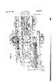
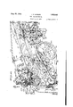
Referring in detail to the drawings, wherein the same reference characters are employed to designate corresponding parts in the several guresz- Figs. 1, la, and 1b, together constitute an elevation of the machine, Fig. 1 being an elevation of the power end of the machine, Fig. 1a being an elevation of the intermediate portion of the nmchine, and Fig. 1b being Van elevation of the tail end of the machine;
Figs. 2, 2a, and 2b are axial sections through the machine, Fig. 2 being an axial section through the power end of the machine, Fig. 2a being an axial section through the intermediate portion of the machine and showing the punch in elevated inoperative position, and Fig. 2b being an Yaxial section through the tail end of the machine showing the position of the parts at the end of the drawing operation;
Figs. 3, 3, and 3b are plan views of the machine, Fig. 3 being a plan of the power end of the machine, Fig. 3a being a plan view of the intermediate portion of the machine, and Fig. 3b being a plan view of the tail end of the machine, the parts being shown in the same relative positions as in Figs. 2, 2R, and 2b;
Figs. 4, 4R, and 4b are sectional views through the punch, chuck and chuck-operating means, Fig. 4 being a sectional View through the rearward end of the punch, Fig. 4a being a sectional
Priority Applications (1)
| Application Number | Priority Date | Filing Date | Title |
|---|---|---|---|
| US375161A US1925035A (en) | 1929-07-01 | 1929-07-01 | Tube drawing machine |
Applications Claiming Priority (1)
| Application Number | Priority Date | Filing Date | Title |
|---|---|---|---|
| US375161A US1925035A (en) | 1929-07-01 | 1929-07-01 | Tube drawing machine |
Publications (1)
| Publication Number | Publication Date |
|---|---|
| US1925035A true US1925035A (en) | 1933-08-29 |
Family
ID=23479745
Family Applications (1)
| Application Number | Title | Priority Date | Filing Date |
|---|---|---|---|
| US375161A Expired - Lifetime US1925035A (en) | 1929-07-01 | 1929-07-01 | Tube drawing machine |
Country Status (1)
| Country | Link |
|---|---|
| US (1) | US1925035A (en) |
Cited By (2)
| Publication number | Priority date | Publication date | Assignee | Title |
|---|---|---|---|---|
| US2492876A (en) * | 1943-12-20 | 1949-12-27 | Vaughn Machinery Co | Drawbench |
| US3036696A (en) * | 1959-02-24 | 1962-05-29 | Reisholz Stahl & Roehrenwerk | Method of producing seamless tubular articles |
-
1929
- 1929-07-01 US US375161A patent/US1925035A/en not_active Expired - Lifetime
Cited By (2)
| Publication number | Priority date | Publication date | Assignee | Title |
|---|---|---|---|---|
| US2492876A (en) * | 1943-12-20 | 1949-12-27 | Vaughn Machinery Co | Drawbench |
| US3036696A (en) * | 1959-02-24 | 1962-05-29 | Reisholz Stahl & Roehrenwerk | Method of producing seamless tubular articles |
Similar Documents
| Publication | Publication Date | Title |
|---|---|---|
| CN106311915A (en) | Automatic hole expanding equipment for taper holes in end parts of pipes | |
| US2228301A (en) | Tube drawing method and apparatus | |
| US1925035A (en) | Tube drawing machine | |
| US2089475A (en) | Machine for forming beads in metallic drums | |
| US2161076A (en) | Method of and apparatus for reeling strip material | |
| US2635492A (en) | Plug-handling mechanism for seamless tube mills | |
| US819261A (en) | Apparatus for treating heated metal under pressure. | |
| US1859990A (en) | Metal extrusion press | |
| US2412979A (en) | Manufacture of milled toilet soap | |
| US2691906A (en) | Sizing pipe ends | |
| US2221417A (en) | Means for finishing bends | |
| US1913206A (en) | Manufacture of tubes | |
| US2285539A (en) | Drawing mandrel or plug | |
| US3370449A (en) | Billet extrusion presses | |
| US1625340A (en) | Method of making well points | |
| CN108145973A (en) | A kind of 3D printer for being used to make model | |
| US2374794A (en) | Method and apparatus for electrically forming pipe | |
| US961132A (en) | Machine for forming seamless tubes. | |
| US2011907A (en) | Tube making | |
| US1575768A (en) | Lead covering of electric cables and the like by extrusion | |
| US2988812A (en) | Method of fabricating tubular units | |
| US887718A (en) | Extrusion-machine. | |
| DE719941C (en) | Device for smoothing and loosening the pipes produced on a push bench from the mandrel bar | |
| GB768593A (en) | A method and means for passing tube blanks through step rolling mills | |
| GB1116901A (en) | Methods and apparatus for manufacturing tubular products from tubular blooms |