US1925017A - Rat-hole packer - Google Patents
Rat-hole packer Download PDFInfo
- Publication number
- US1925017A US1925017A US634599A US63459932A US1925017A US 1925017 A US1925017 A US 1925017A US 634599 A US634599 A US 634599A US 63459932 A US63459932 A US 63459932A US 1925017 A US1925017 A US 1925017A
- Authority
- US
- United States
- Prior art keywords
- packer
- head
- tubing string
- pass
- rat
- Prior art date
- Legal status (The legal status is an assumption and is not a legal conclusion. Google has not performed a legal analysis and makes no representation as to the accuracy of the status listed.)
- Expired - Lifetime
Links
- 238000012856 packing Methods 0.000 description 12
- 238000005553 drilling Methods 0.000 description 4
- 239000012530 fluid Substances 0.000 description 4
- 238000009825 accumulation Methods 0.000 description 2
- 230000015572 biosynthetic process Effects 0.000 description 2
- 230000002706 hydrostatic effect Effects 0.000 description 2
- 230000000740 bleeding effect Effects 0.000 description 1
- 230000006835 compression Effects 0.000 description 1
- 238000007906 compression Methods 0.000 description 1
- 230000003028 elevating effect Effects 0.000 description 1
- 239000000463 material Substances 0.000 description 1
- 230000000284 resting effect Effects 0.000 description 1
- 230000000007 visual effect Effects 0.000 description 1
Images
Classifications
-
- E—FIXED CONSTRUCTIONS
- E21—EARTH OR ROCK DRILLING; MINING
- E21B—EARTH OR ROCK DRILLING; OBTAINING OIL, GAS, WATER, SOLUBLE OR MELTABLE MATERIALS OR A SLURRY OF MINERALS FROM WELLS
- E21B33/00—Sealing or packing boreholes or wells
- E21B33/10—Sealing or packing boreholes or wells in the borehole
- E21B33/12—Packers; Plugs
Definitions
- the present invention is an improved rat-hole or liner type packer for use in wells which have,
- the objects of this invention include:- The provision of a packer for the uses specified, wherein is provided a central by-pass extending thru the packing elements, and affording means for fluid passage therethrough, said packer being a separable structure provided with yieldable means for holding the separable parts apart as the device is run in through dense drilling mud commonly employed in rotary drilling.
- the purposeof said secondary valve is to facilitate the release of the packer after having been set.
- the first upward movement of the tubing string, before actual lifting strain is applied to pull the packer, is eifective to open said by pass, and cause a sudden equalization of hydrostatic pressure above and below the packing element.
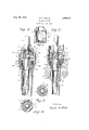
- Figure 1 is a vertical cross sectional view of my packer as it would appearat rest upon the shoulder of the rat-hole in open formation before weight of the tubing string, from which it is suspended, had been applied to deform the packing elements.
- Figure 2 is a similar view of the same packer, in set position, but here shown as employed to pack around a well casing shoe, said packer resting on a liner hanger of conventional type.
- Figure 3 is a section of Figure 1 taken on the doted line Ill-HI of said figure.
- Figure 4 is a section of Figure 1 taken on the line IV- LV of said figure.
- Figure 5 is a sectional view ofa modified de tail.
- the numeral 1 indicates the lowermost member of a tubing string from which my packer is suspended.
- Tubing l is threaded at 2 to engage a collar 3.
- a slip head, member a is slidable on tubing 1, and over collar 3, and is provided with an annular groove 6 which the head 4: are compressed as shown in Figure 2.
- Groove 6 is closed and passages ll sealed in this position by an annular tongue member 14 integral with collar 3.
- a pointed tube 16 provided with perforations 17 is threaded at 18 into the head a and conducts fluid from the zone below the packer thru a chamber 19 in said head to the tubing string l.
- a collar 21 secured to tube 16 supports the foot member 13 and said foot member and thehead d are normally held apart as the packer is run in, by an expansion spring 22, one end of which bears against said head, and the other end against lugs 23, Figure '4, integral withsaid foot member.
- Said lugs also serve to align said foot member with tube 16 upon which it slides.
- Foot member 13 is here shown as built upof' a series of laminated sheets A and B of woven or reinforced material, such as belting, adapted to be deformed by compression between the head 4 and foot 13 and thereby seal the well or casing, as the case may be, against passage of fluid therethrough, as shown in Figure 2.
- foot member 13 is shown in deformed position, being compressed by weight of tubing string 1. Said weight is transmitted thru collar 3 which bears against groove 6 closing same, and this pressure collapses spring 22, causing head 4 to contact the upper surface of foot 13, de-
- foot member 13 rests on a liner hanger 26 from which is suspended a liner 2'7.
- My packer is run in a well on a tubing string 1 until the foot member 13 encounters an obstruction at the bottom (shoulder 28 or liner hanger 26). As the packer is being lowered thru dense drilling mud or other fluid, spring 22 holds head 4 and foot 13 out of contact, and the mud is displaced through by-pass 12 and out between said members.
- the bleeder was then opened by droppinga weight, and lifting strain again applied.
- the packer and tubing string was then removed with a lifting power the maximum of which was much less in amount than that of the previously recorded reading.
- Figure 5 I show an elongated form of the slip head 4 in which the ports 8 are disposed in helical arrangement therethrough and their number increased, and more room is provided for movement within said head of the collar 3.
- This structure provides a means for throttling the capacity of the ports 8 by positioning the said collar. This makes it possible to equalize pressure above and below the packer, either gradually or suddenly as heretofore described.
- Another instance of the advantage of this structure is manifest in the removal of gas accumulation in the zone below the packer.
- collar 3 can be lifted to uncover as many of ports 8 as are required to accommodate the gas flow and relieve said pressure accumulation.
- a device of the character disclosed comprising a pair of sections of tubing joined in an endto-end relation in a manner providing a limited degree of relative movement, a packing element, slidable on the lower of said sections, adapted, when deformed, to'seal the space between said section and an adjacent wall, said element having a by-pass channel therethrough, connecting the zones above and below said packing, outside of and independent of said tubing, a head member secured to said lower section and slidable with respect to the upper of said sections, having ports therethrough adapted to register with the by-pass channel thru said packing element, means, responsive to weight of the upper tubing section, for actuating said head member to deform said packing element and close said by-pass, means, responsive to movement of said upper section for selectively opening and closing said ports while said by-pass is-closed by said head member, and
- a packer of the character disclosed comprising a sectional tubing string, wherein sections are joined in end-to-end relation by slip-joint struc above said packing element, a closure, associated with the upper of said tubing sections, adapted to open and close said ports when said upper section is reciprocated, and an expansion spring urging said head member and said packing element apart and keeping said flow channel open.
Landscapes
- Life Sciences & Earth Sciences (AREA)
- Engineering & Computer Science (AREA)
- Geology (AREA)
- Mining & Mineral Resources (AREA)
- Physics & Mathematics (AREA)
- Environmental & Geological Engineering (AREA)
- Fluid Mechanics (AREA)
- General Life Sciences & Earth Sciences (AREA)
- Geochemistry & Mineralogy (AREA)
- Pipe Accessories (AREA)
- Earth Drilling (AREA)
Description
W. T. WELLS RAT HOLE PACKER Aug. 29, 1933.
Filed Sept. 23, 1952 //v VENTOR) Patented Aug; 29, 1933 srares FATE Application September 23, 11932 Serial N47). 634,59@
2 (Claims. (Cl. ltdlt) The present invention is an improved rat-hole or liner type packer for use in wells which have,
packer oi the type herein described.
The objects of this invention include:- The provision of a packer for the uses specified, wherein is provided a central by-pass extending thru the packing elements, and affording means for fluid passage therethrough, said packer being a separable structure provided with yieldable means for holding the separable parts apart as the device is run in through dense drilling mud commonly employed in rotary drilling.
The provision in a rat-hole packer wherein a central by-pass extending therethrough is closed by compressive force applied to head and foot members, one of which is secured to, and the other slidable on, a tubing string, of a secondary valve controlling a bleeder passage which com municates with said by-pass.
The purposeof said secondary valve is to facilitate the release of the packer after having been set.
In the structure hereinafter described the first upward movement of the tubing string, before actual lifting strain is applied to pull the packer, is eifective to open said by pass, and cause a sudden equalization of hydrostatic pressure above and below the packing element.
Field experience shows that fewer units of weight are recorded on the weight indicator of the derrick rig when the packer is lifted in this manner.
By breaking the hydraulic lock at the bottom by the use of my bleeder valve, much less strain is imposed on the elevator. This is an important advantage of my invention which makes its use of advantage in deep wells wherein long heavy strings of tubing are run in and out thru dense drilling mud. It also makes certain the removal of a packer under extreme pressure conditions and eliminates the necessity of lifting the entire area against the resistance of heavy rotary mud.
In the accompanying drawing, Figure 1 is a vertical cross sectional view of my packer as it would appearat rest upon the shoulder of the rat-hole in open formation before weight of the tubing string, from which it is suspended, had been applied to deform the packing elements.
Figure 2 is a similar view of the same packer, in set position, but here shown as employed to pack around a well casing shoe, said packer resting on a liner hanger of conventional type.
Figure 3 .is a section of Figure 1 taken on the doted line Ill-HI of said figure.
Figure 4 is a section of Figure 1 taken on the line IV- LV of said figure, and
Figure 5 is a sectional view ofa modified de tail.
Referring to the drawing, the numeral 1 indicates the lowermost member of a tubing string from which my packer is suspended. Tubing l is threaded at 2 to engage a collar 3. A slip head, member a is slidable on tubing 1, and over collar 3, and is provided with an annular groove 6 which the head 4: are compressed as shown in Figure 2.
A pointed tube 16 provided with perforations 17 is threaded at 18 into the head a and conducts fluid from the zone below the packer thru a chamber 19 in said head to the tubing string l.
A collar 21 secured to tube 16 supports the foot member 13 and said foot member and thehead d are normally held apart as the packer is run in, by an expansion spring 22, one end of which bears against said head, and the other end against lugs 23, Figure '4, integral withsaid foot member.
Said lugs also serve to align said foot member with tube 16 upon which it slides.
Here the foot member 13 is shown in deformed position, being compressed by weight of tubing string 1. Said weight is transmitted thru collar 3 which bears against groove 6 closing same, and this pressure collapses spring 22, causing head 4 to contact the upper surface of foot 13, de-
forming the laminated packing A and B and setting the packer. V
In Figure 2, foot member 13 rests on a liner hanger 26 from which is suspended a liner 2'7.
In that type of well shown in Figure 1 said foot member rests on a shoulder 28 of formation.
Operation My packer is run in a well on a tubing string 1 until the foot member 13 encounters an obstruction at the bottom (shoulder 28 or liner hanger 26). As the packer is being lowered thru dense drilling mud or other fluid, spring 22 holds head 4 and foot 13 out of contact, and the mud is displaced through by-pass 12 and out between said members.
As soon as foot member 13 is interrupted in its travel, the descending tubing string moves collar 3 downwardly until tongue 14 closes groove 6 in the head 4, and the weight of said tubing string collapses spring 22, bringing head and foot 13 into contact, closing by-pass l2 and deforming the packing elements AB, and setting the packer.
When it is desired to remove the packer the tubing string is raised, and the first upward movement thereof lifts collar 3, uncovering ports 8, whereupon hydrostatic pressure in the well zone above the packer passes thru said ports 8, thru passages 11, and thru by-pass 12 to the zone below the packer.
.The suddenness of this operation produces an impact of sufficient force to jar the packer looses. and relieve the elevating rig from undue strain of hydraulic lock.
This fact has been clearly demonstrated by the weight indicator on the derrick. During early experiments this bleeding of the by-pass was accomplished by dropping a go-devil from the top thru the tubing string.
Before this was done a lifting force more than sufiicient to lift the suspended string but not enough to dislodge the packer was applied to the tubing string. A reading was taken from the weight indicator dial and recorded.
The bleeder was then opened by droppinga weight, and lifting strain again applied. The packer and tubing string was then removed with a lifting power the maximum of which was much less in amount than that of the previously recorded reading.
'In addition to this gauge reading, visual proof was afforded by the fact that at the instant the go-devil struck, the pipe string surged upward and ofiered no resistance, other than dead weight, to its removal.
In Figure 5 I show an elongated form of the slip head 4 in which the ports 8 are disposed in helical arrangement therethrough and their number increased, and more room is provided for movement within said head of the collar 3.
This structure provides a means for throttling the capacity of the ports 8 by positioning the said collar. This makes it possible to equalize pressure above and below the packer, either gradually or suddenly as heretofore described.
Another instance of the advantage of this structure is manifest in the removal of gas accumulation in the zone below the packer.
While the primary valve (contact between head 4 and foot 13) is closed, collar 3 can be lifted to uncover as many of ports 8 as are required to accommodate the gas flow and relieve said pressure accumulation.
I claim:-
1. A device of the character disclosed, comprising a pair of sections of tubing joined in an endto-end relation in a manner providing a limited degree of relative movement, a packing element, slidable on the lower of said sections, adapted, when deformed, to'seal the space between said section and an adjacent wall, said element having a by-pass channel therethrough, connecting the zones above and below said packing, outside of and independent of said tubing, a head member secured to said lower section and slidable with respect to the upper of said sections, having ports therethrough adapted to register with the by-pass channel thru said packing element, means, responsive to weight of the upper tubing section, for actuating said head member to deform said packing element and close said by-pass, means, responsive to movement of said upper section for selectively opening and closing said ports while said by-pass is-closed by said head member, and
means, yieldable to the weight of said upper tubing section, holding said head member and said packing element apart, and said by-pass open, while the device is being raised or lowered.
' 2. A packer of the character disclosed compris- V ing a sectional tubing string, wherein sections are joined in end-to-end relation by slip-joint struc above said packing element, a closure, associated with the upper of said tubing sections, adapted to open and close said ports when said upper section is reciprocated, and an expansion spring urging said head member and said packing element apart and keeping said flow channel open.
WALTER T. WELLS.
Priority Applications (1)
| Application Number | Priority Date | Filing Date | Title |
|---|---|---|---|
| US634599A US1925017A (en) | 1932-09-23 | 1932-09-23 | Rat-hole packer |
Applications Claiming Priority (1)
| Application Number | Priority Date | Filing Date | Title |
|---|---|---|---|
| US634599A US1925017A (en) | 1932-09-23 | 1932-09-23 | Rat-hole packer |
Publications (1)
| Publication Number | Publication Date |
|---|---|
| US1925017A true US1925017A (en) | 1933-08-29 |
Family
ID=24544460
Family Applications (1)
| Application Number | Title | Priority Date | Filing Date |
|---|---|---|---|
| US634599A Expired - Lifetime US1925017A (en) | 1932-09-23 | 1932-09-23 | Rat-hole packer |
Country Status (1)
| Country | Link |
|---|---|
| US (1) | US1925017A (en) |
Cited By (1)
| Publication number | Priority date | Publication date | Assignee | Title |
|---|---|---|---|---|
| US3231020A (en) * | 1963-06-17 | 1966-01-25 | Jr Haskell M Greene | Closing of wells at points of diameter change |
-
1932
- 1932-09-23 US US634599A patent/US1925017A/en not_active Expired - Lifetime
Cited By (1)
| Publication number | Priority date | Publication date | Assignee | Title |
|---|---|---|---|---|
| US3231020A (en) * | 1963-06-17 | 1966-01-25 | Jr Haskell M Greene | Closing of wells at points of diameter change |
Similar Documents
| Publication | Publication Date | Title |
|---|---|---|
| US4429747A (en) | Well tool | |
| US5810087A (en) | Formation isolation valve adapted for building a tool string of any desired length prior to lowering the tool string downhole for performing a wellbore operation | |
| US4047564A (en) | Weight and pressure operated well testing apparatus and its method of operation | |
| US4076077A (en) | Weight and pressure operated well testing apparatus and its method of operation | |
| US2951536A (en) | Method and apparatus for remote control of valves or the like | |
| US4109724A (en) | Oil well testing valve with liquid spring | |
| US3659648A (en) | Multi-element packer | |
| US4274486A (en) | Apparatus for and method of operating a well | |
| USRE29638E (en) | Pressure controlled test valve system for offshore wells | |
| US2740479A (en) | Drill stem testing device | |
| US3247904A (en) | Dual completion tool | |
| US2391605A (en) | Well flow device | |
| US4440230A (en) | Full-bore well tester with hydrostatic bias | |
| US4059157A (en) | Well control valve apparatus | |
| US4281715A (en) | Bypass valve | |
| US2928469A (en) | Well packer with ejectable plug | |
| US3901314A (en) | Pressure controlled tester valve | |
| US2802535A (en) | Paraffin scraper | |
| US3118502A (en) | Well completion apparatus | |
| US4538680A (en) | Gun below packer completion tool string | |
| US1925017A (en) | Rat-hole packer | |
| US3280917A (en) | Well tester | |
| US2962099A (en) | Blowout control valve | |
| US1925015A (en) | Formation packer | |
| US1926017A (en) | Packer |