US1922685A - Valve structure - Google Patents
Valve structure Download PDFInfo
- Publication number
- US1922685A US1922685A US565250A US56525031A US1922685A US 1922685 A US1922685 A US 1922685A US 565250 A US565250 A US 565250A US 56525031 A US56525031 A US 56525031A US 1922685 A US1922685 A US 1922685A
- Authority
- US
- United States
- Prior art keywords
- valve
- spring
- casing
- flange
- piston
- Prior art date
- Legal status (The legal status is an assumption and is not a legal conclusion. Google has not performed a legal analysis and makes no representation as to the accuracy of the status listed.)
- Expired - Lifetime
Links
- 230000000994 depressogenic effect Effects 0.000 description 2
- 230000000717 retained effect Effects 0.000 description 2
- 238000010276 construction Methods 0.000 description 1
Images
Classifications
-
- G—PHYSICS
- G10—MUSICAL INSTRUMENTS; ACOUSTICS
- G10D—STRINGED MUSICAL INSTRUMENTS; WIND MUSICAL INSTRUMENTS; ACCORDIONS OR CONCERTINAS; PERCUSSION MUSICAL INSTRUMENTS; AEOLIAN HARPS; SINGING-FLAME MUSICAL INSTRUMENTS; MUSICAL INSTRUMENTS NOT OTHERWISE PROVIDED FOR
- G10D9/00—Details of, or accessories for, wind musical instruments
- G10D9/04—Valves; Valve controls
Definitions
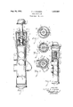
- Fig. 1 is an enlarged detail vertical central sectional view on line 11 of Figs. 3, 4 and! of a piston valve for cupped mouthpiece wind instrument, the valve and spring structure'being shown in full lines, the valve being in up-position.
- Fig. 2 is a similar sectional view with the valve in down-position.
- Fig. 3 is a detail cross sectional view on line 33 of Fi'gs'l and 2 showing details of thetop spring supporting flange, and its engagement with the spring.
- Fig. 4 is a detail transverse sectional view on line 4-4 of Fig. 2, showing the details of the bottom spring supporting flange and its engagement with the spring.
- Fig. 5 is a detail transverse sectional view on line 5-5 of Fig. 1 showing the details of the valve piston guide.
- 1 is the valve casing. 2 is the piston valve of any desired or required form. 3 is the key provided with a cushion pad 31 on its under side. 4
- 41 is the piston head to which the key stem is riveted or otherwise secured.
- 5 is the casing head.
- 6 is the screw cap for the head terminating in a hub or boss 61 perforated with a hole at the center through which the key stem 4 reciprocates.
- 42 is a stop collar on the key stem above which is a cushion washer 43 to insure the noiseless action when the valve returns to the tip-position.
- the cylindrical expansion coil spring which supports the key in the up-position and permits it to be yieldingly depressed.
- the upper coil of the spring is secured to the supporting flange 8 which rests upon the end of the casing head and is retained by the screw cap 6.
- the flange 8 is conformed to form a seat for the top coil of the spring 7 which is deflected under the lug 81, see Fig. 3, to insure its engagement under tension.
- the spring is thus evenly held so that the full elasticity of the coils is secured without disturbing its connection to the flange.
- FIG. 9 is the lower supporting flange for the spring which is secured by an adjustable screw threaded hub 10.
- the periphery of this flange is likewise iormed into a seat 91 with an engaging lug 92 to support the bottom coil of the spring under tension.
- ' i1 is a guiding lug secured to the top of the Valve 2 by the lock nut 23 clamping against the washer 24.
- the end of this guide lug is upturn ed and a way 12 is formed in the'side of the casing 2 and of thezcasing head 5, so that the valve is accurately guided to position.
- This is for regular piston construction.
- My improved spring is especially well adapted for usein connection with the improvements appearing in my application for Letters Patent filed August 26, 1929, Serial No. 388,563, in which the valve piston has a guided spiral reciprocatory movement.
- valve casing a reciprocating piston therein, a valve casing head, a screw cap therefor having a central perforated hub, a piston valve within said casing, a stem tained by the said cap having a central seat and 106 engaging lug for "the top coil of the said spring, a bottom supporting flange therefor'the periph cry of said flange being formed with a seat and lug for the bottom coil of the said spring, and a ably on the said stem.
- valve casing a reciprocating piston, therein, a valve casing head, a screw cap therefor having a central perforated hub, a piston valve within said casing a stem 110 screw threaded hub to carry.
- said flange adjust- ATEN OFFICE
Landscapes
- Physics & Mathematics (AREA)
- Engineering & Computer Science (AREA)
- Acoustics & Sound (AREA)
- Multimedia (AREA)
- Safety Valves (AREA)
Description
A. J. JOHNSON VALVE STRUCTURE Aug. 15, 1933.
Filed Sept. 26, 1951 n I O m m W m m T J dww CB Patented Aug. 15, 1933' 1,922,685 VALVE STRUCTURE Alfred J; Johnson, Grand Rapids, Mich, assignor to York Band Instrument Company, v Grand Rapids, Mich.
Application September 26, 1931. Serial No. 565,250
3 Claims. (o1. 4-392) This invention relates to improvements in valve structures for cupped mouthpiecewind instruments. g g
The objects of the invention are:
First, to provide such a structure in which the tails will appear from the description to follow.
A preferred embodiment of the invention is illustrated in the accompanying drawing, in which: Fig. 1 is an enlarged detail vertical central sectional view on line 11 of Figs. 3, 4 and!) of a piston valve for cupped mouthpiece wind instrument, the valve and spring structure'being shown in full lines, the valve being in up-position.
Fig. 2 is a similar sectional view with the valve in down-position. v
Fig. 3 is a detail cross sectional view on line 33 of Fi'gs'l and 2 showing details of thetop spring supporting flange, and its engagement with the spring.
Fig. 4 is a detail transverse sectional view on line 4-4 of Fig. 2, showing the details of the bottom spring supporting flange and its engagement with the spring.
Fig. 5 is a detail transverse sectional view on line 5-5 of Fig. 1 showing the details of the valve piston guide.
The parts will be identified by their numerals of reference.
1 is the valve casing. 2 is the piston valve of any desired or required form. 3 is the key provided with a cushion pad 31 on its under side. 4
is the key stem. 41 is the piston head to which the key stem is riveted or otherwise secured. 5 is the casing head. 6 is the screw cap for the head terminating in a hub or boss 61 perforated with a hole at the center through which the key stem 4 reciprocates. 42 is a stop collar on the key stem above which is a cushion washer 43 to insure the noiseless action when the valve returns to the tip-position. 1
7 is the cylindrical expansion coil spring which supports the key in the up-position and permits it to be yieldingly depressed. 'The upper coil of the spring is secured to the supporting flange 8 which rests upon the end of the casing head and is retained by the screw cap 6. The flange 8 is conformed to form a seat for the top coil of the spring 7 which is deflected under the lug 81, see Fig. 3, to insure its engagement under tension.
The spring is thus evenly held so that the full elasticity of the coils is secured without disturbing its connection to the flange.
9 is the lower supporting flange for the spring which is secured by an adjustable screw threaded hub 10. The periphery of this flange is likewise iormed into a seat 91 with an engaging lug 92 to support the bottom coil of the spring under tension. By referring to Figs. 1 and 2 it will be I seen that when the valve is in the up-position, the coilsare quite close together and when the valve is depressed the spring is expanded. This secures a very soft, even, noiseless action with no opportunity for the coils of the springs to contact one with another and the pull on the spring is 6? even and increases in regular ratio, but not rapidly because of the length of the spring.
' i1 is a guiding lug secured to the top of the Valve 2 by the lock nut 23 clamping against the washer 24. The end of this guide lug is upturn ed and a way 12 is formed in the'side of the casing 2 and of thezcasing head 5, so that the valve is accurately guided to position.' This is for regular piston construction. My improved spring is especially well adapted for usein connection with the improvements appearing in my application for Letters Patent filed August 26, 1929, Serial No. 388,563, in which the valve piston has a guided spiral reciprocatory movement.
It will be seen that my structure can be much modified without departing from my invention. I desire to claim the invention specifically as illustrated and also broadly as pointed out in'the appended claims;
Having thus described my invention, what I 9 claim as new and desire to secure by Letters Patent is: V
1. The combination or" a valve casing, a reciprocating piston therein, a valve casing head, a screw cap therefor having a central perforated hub, a piston valve within said casing, a stem tained by the said cap having a central seat and 106 engaging lug for "the top coil of the said spring, a bottom supporting flange therefor'the periph cry of said flange being formed with a seat and lug for the bottom coil of the said spring, and a ably on the said stem.
2. The combination of a valve casing, a reciprocating piston, therein, a valve casing head, a screw cap therefor having a central perforated hub, a piston valve within said casing a stem 110 screw threaded hub to carry. said flange adjust- ATEN OFFICE;
2 therefor adapted to reciprocate through the said hub, a slidable guide member carried by said piston, a guide way formed'in the said casing and casing head, a cylindrical expansion coiled spring for said valve, a top supporting flange therefor retained by the said cap having a central seat and engaging lugifor the top coil of the said spring, a bottom supporting flange therefor the periphery of said flange being formed. with a seat and lug for the bottom coil of the the top of the said casing, and a flange to connect 7 the lower end to the said stem.
. ALFRED J. JOHNSON.
Priority Applications (1)
| Application Number | Priority Date | Filing Date | Title |
|---|---|---|---|
| US565250A US1922685A (en) | 1931-09-26 | 1931-09-26 | Valve structure |
Applications Claiming Priority (1)
| Application Number | Priority Date | Filing Date | Title |
|---|---|---|---|
| US565250A US1922685A (en) | 1931-09-26 | 1931-09-26 | Valve structure |
Publications (1)
| Publication Number | Publication Date |
|---|---|
| US1922685A true US1922685A (en) | 1933-08-15 |
Family
ID=24257799
Family Applications (1)
| Application Number | Title | Priority Date | Filing Date |
|---|---|---|---|
| US565250A Expired - Lifetime US1922685A (en) | 1931-09-26 | 1931-09-26 | Valve structure |
Country Status (1)
| Country | Link |
|---|---|
| US (1) | US1922685A (en) |
Cited By (4)
| Publication number | Priority date | Publication date | Assignee | Title |
|---|---|---|---|---|
| US4696454A (en) * | 1985-06-26 | 1987-09-29 | Nippon Gakki Seizo Kabushiki Kaisha | Valve shifting mechanism for a brass instrument |
| EP0339456A3 (en) * | 1988-04-27 | 1990-12-27 | Miraphone Graslitzer Musikinstrumenten-Erzeuger eG | Device for operating a cylinder-valve of a brass instrument |
| US20150317961A1 (en) * | 2012-12-19 | 2015-11-05 | Warwick Music Limited | Fluid Flow Control Valves |
| US12331841B2 (en) | 2022-04-13 | 2025-06-17 | Bajoc Music Enterprises, LLC | Valve guide with external return spring for musical instrument |
-
1931
- 1931-09-26 US US565250A patent/US1922685A/en not_active Expired - Lifetime
Cited By (5)
| Publication number | Priority date | Publication date | Assignee | Title |
|---|---|---|---|---|
| US4696454A (en) * | 1985-06-26 | 1987-09-29 | Nippon Gakki Seizo Kabushiki Kaisha | Valve shifting mechanism for a brass instrument |
| EP0339456A3 (en) * | 1988-04-27 | 1990-12-27 | Miraphone Graslitzer Musikinstrumenten-Erzeuger eG | Device for operating a cylinder-valve of a brass instrument |
| US20150317961A1 (en) * | 2012-12-19 | 2015-11-05 | Warwick Music Limited | Fluid Flow Control Valves |
| US9765901B2 (en) * | 2012-12-19 | 2017-09-19 | Warwick Music Limited | Fluid flow control valves |
| US12331841B2 (en) | 2022-04-13 | 2025-06-17 | Bajoc Music Enterprises, LLC | Valve guide with external return spring for musical instrument |
Similar Documents
| Publication | Publication Date | Title |
|---|---|---|
| US2210206A (en) | Automatic fluid dispenser | |
| US1328488A (en) | Dust-cap and attaching means therefor | |
| US1922685A (en) | Valve structure | |
| US2332042A (en) | Spring structure | |
| US1392587A (en) | Pressure-gage | |
| US3036744A (en) | Aerosol valve construction | |
| US2246775A (en) | Pneumatic tire valve | |
| US2612811A (en) | Valve for wind instruments | |
| US2037499A (en) | Fuel tank closing cap | |
| US1938321A (en) | Wind musical instrument | |
| US1596655A (en) | Valve for cornets and the like | |
| US1984704A (en) | Wind musical instrument | |
| US2492471A (en) | Pocket lighter with removable mechanical unit | |
| US1422278A (en) | Pressure gauge | |
| US2165267A (en) | Pressure actuated valve | |
| US2300606A (en) | Coffee maker | |
| US1821397A (en) | Piston valve for wind instruments | |
| US2232238A (en) | Moving valve single reed | |
| US2149714A (en) | Valve for brass wind instruments | |
| US1593313A (en) | Tire valve | |
| US2007994A (en) | Saddle | |
| US1611451A (en) | Powder-dusting brush | |
| DE814103C (en) | Motor vehicle seat | |
| US1617299A (en) | Means for securing dust caps for valve stems | |
| US1674398A (en) | Piston valve for cornets |