US1921237A - Tile making machine - Google Patents
Tile making machine Download PDFInfo
- Publication number
- US1921237A US1921237A US467459A US46745930A US1921237A US 1921237 A US1921237 A US 1921237A US 467459 A US467459 A US 467459A US 46745930 A US46745930 A US 46745930A US 1921237 A US1921237 A US 1921237A
- Authority
- US
- United States
- Prior art keywords
- tile
- bit
- shaft
- bell
- making machine
- Prior art date
- Legal status (The legal status is an assumption and is not a legal conclusion. Google has not performed a legal analysis and makes no representation as to the accuracy of the status listed.)
- Expired - Lifetime
Links
- 239000000463 material Substances 0.000 description 7
- 230000000153 supplemental effect Effects 0.000 description 7
- 238000000465 moulding Methods 0.000 description 5
- 239000011324 bead Substances 0.000 description 3
- 239000002184 metal Substances 0.000 description 1
- 238000012856 packing Methods 0.000 description 1
- 238000005192 partition Methods 0.000 description 1
- 230000000284 resting effect Effects 0.000 description 1
- 239000004576 sand Substances 0.000 description 1
Images


Classifications
-
- B—PERFORMING OPERATIONS; TRANSPORTING
- B28—WORKING CEMENT, CLAY, OR STONE
- B28B—SHAPING CLAY OR OTHER CERAMIC COMPOSITIONS; SHAPING SLAG; SHAPING MIXTURES CONTAINING CEMENTITIOUS MATERIAL, e.g. PLASTER
- B28B21/00—Methods or machines specially adapted for the production of tubular articles
- B28B21/02—Methods or machines specially adapted for the production of tubular articles by casting into moulds
- B28B21/10—Methods or machines specially adapted for the production of tubular articles by casting into moulds using compacting means
- B28B21/22—Methods or machines specially adapted for the production of tubular articles by casting into moulds using compacting means using rotatable mould or core parts
- B28B21/24—Methods or machines specially adapted for the production of tubular articles by casting into moulds using compacting means using rotatable mould or core parts using compacting heads, rollers, or the like
- B28B21/26—Methods or machines specially adapted for the production of tubular articles by casting into moulds using compacting means using rotatable mould or core parts using compacting heads, rollers, or the like with a packer head serving as a sliding mould or provided with guiding means for feeding the material
Definitions
- Another object is to provide machines which can be operated economically and with speed in turning out tile in large quantities and to provide machines which have interchangeable molding devices. Another object is to provide machines with molding and turning apparatus and devices for making tile which will interlock with each other and which will be automatically self aligning or self centering of adjacent end members; and to provide machines for making building blocks, partition blocks, floor blocks, cylindrical tile for drainage purposes, and to provide tile withbells on the ends and beads on adjacent ends of the bells for causing self aligning or self 'centering'of the beaded ends in the bells, and to provide machines for making building blocks of tile.
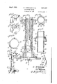
- Fig. 1 is a side elevation of the machineprovided with a single molding equipment.
- Fig. 2 is a perspective view of a mold form supporting device.
- Fig. 3 is a'front elevation of a portion of the machine having a double mold form.
- Fig. 4 is a perspective view of the double mold form, partly in section.
- Fig. 5 is a longitudinal section of the same.
- Fig. 6 is a perspective view of the machine shown in Fig. 1.
- Fig. 7 is a front elevation of being omitted.
- Fig. 8 is detail view of the bell forming device.
- Fig. 9- is a plan view of the gear shifting clutches.
- Fig. 10 is a plan view of the bell forming device shown in Fig. 8. a
- Fig. 11 is a perspective view of a mold form for making rectangular tile.
- Fig. 12 is a vertical section of a mold for making tubular or cylindrical tile.
- Fig. 13 is a plan view of the same.
- Fig. 14 illustrates a supplemental support or base for one type of mold.
- Fig. 15 shows a variation in the mold clamping means.
- Fig. 16 shows a section of two tiles joined, illustrating the self centering function of the tiles.
- Fig. 17 is a perspective view of the gear shifting devices.
- Fig. 18 is a perspective view of a bitused in the machine. 7
- the machine is provided with a'base frame having beams 1 and 2 and uprights 3 and 4 and the uprights 3 and 4 are provided with braces 5.
- the uprights 3 and 4 are braced at their upper ends by cross bar 6.
- the frame is also provided with base 7 for supporting operating mechanism.
- the frame is provided with platforms and supporting devices for adapting the machine for use with a variety of forms for molding and forming hollow tile of different designs. All the operating mechanism is actuated by a common driving mechanism. All the forms are removable and replaceable so that any design of hollow tile may be made with the one machine.
- a cross bar 8 is attached to the frame members sand 4.
- a bearing 9' is attached to the cross bar 8 for a shaft 10.
- a bearing 11 for the other end of shaft 10 is supported on a bracket 12 which is supported on the frame members 3 and 4 and by braces 13.
- the pulley 14 may be driven by any suitable line shaft or other driving means.
- Pulleys 15 and 16 are mounted on shaft 10 and these drive belts 17 and 18, the latter being crossed for giving the required direction to the running of the shaft 19.
- the shaft 19 is journaled in bearings. 20 and. 21.
- the bearing 20 is mounted on cross bar 6 and the bearing 21 is mounted on a bracket 22 which is made rigid by braces 23.
- Pulleys 24 and 25 are loosely mounted on the shaft 19 and are driven by the belts 17 and 18 respectively.
- a double clutch 26 is keyed to the shaft 19 and is slidable thereon.
- the faces of pulleys 24and 25, are provided with clutch teeth to be engaged by the teeth of the double clutch 26.
- the clutch 26 is shifted by a yoke 27 and lever 28.
- One of the pulleys 24 and 25 is used to elevate the operating mechanism and the other is used to lower the operating mechanism.
- a bevel gear wheel 29 is, rigid with shaft 19 and drives a gear wheel 30, which is rotatably mounted on the cross bar 6.
- a vertical shaft 31 is threaded and the gear wheel 30 is interiorly threaded and meshes with the threads of the vertical shaft 31.
- the shaft 31 When the gear wheel 30 isdriven, the shaft 31 is revolved or' driven and runs in the direction determined by the clutch 26 and pulleys 24 and 25.
- the shaft 31 carries and operates a bit 32 for coring out cylindrical openings in tile or pipes and also compresses the plastic material outwardly against the molds.
- the bit 32 forms a bottom in the mold when it is at its lowest position and the major portion of the work done by the bit 32 is when the bit is traveling upwardly in the molds, being driven by the gear wheel 30.
- the bit32 is fixedly but removably attached to the shaft 31.
- Platforms are. provided and attached to the uprights 3 and 4 for supporting molds or forms for making the tile.
- a platform 33 is slidably connected to the uprights 3 and 4.
- the platform 33 forms a frame for supporting the bases of the various types of molds.
- Means are'provided for actuating the platform 33.
- Rods or bars 34 are pivotally connected to the platform 33. These rods are also pivotally connected to the ends of a pair of levers 35.
- the levers 35 are fulcrumed on a shaft 36 which is journaled in bearings 37 which are attached to the uprights 3 and 4.
- the levers 35 are connected to a foot operated bar 38.
- the levers 35 may be rigid with the shaft 36.
- a weight 39 cooperates with the levers 35 and cross bar 38.
- Arm 40 is rigid with shaft 36' and a weight 39 is slidably mounted on the arm 40 to be attached at any desirable point on the arm 40.
- the different molds are elevated by the platform 33 which is I actuated by the levers 35.
- a support 41 is provided for a hopper 42 and this support 41 forms a stop to limit the upward movement of the molds.
- the support 41 is fixedly attached to the uprights 3 and 4.
- the platforms 33 and 41 have relatively large openings therethrough for permitting the passage of all bits.
- Supplemental platforms or supports are provided to be placed on the platforms 33 and 41.
- a pair of supplemental platforms 43 is provided foreach design of mold and a pair of supplemental platforms havefopenings to correspond with the size of the bit openings 3 which receive the bits. Different sizes of bits are required for different sizes of molds. All supplemental platforms are adapted to rest on the platforms 41 and 33. The ends of the molds are countersunk in the supplemental platforms' 43,
- the supplemental platforms 43 are for the purpose I of holding the molds in alignment.
- a bit 44 of special design is providedfor forming the bellsof cylindrical tiles.
- the bit 44 enters the opening 45 which has been made by the bit 32.
- the bit 44 is provided with 2. depending yoke 46.
- the yoke "46 has a rib '47 forentering a slot 48 in bit 32.
- the bit32 is rotated by the gearing hereinafter described and the bit 32 rotates the bit 44 by 'reason of the slot and rib connection.
- the bit 44 forms the bell on the end of the tile.
- Fig. 12 shows the bell 49 and.
- Fig. 16 illustrates a tile 56 on which is formed the bell 49.
- the tile 56 has the end beveled so that the tile will center itself'in the bell.
- the bead or annular rib 57 on the end of the tile is formed by an annular interior groove 58 in the tile form 59.
- the bead 57 forms an additional bearing surface on the outside of the tile for centering purposes.
- the cylindrical tile has an annular rib 60 on the exterior surface and this rib is formed by an annular interior groove 61 in the tile form 59. The object is to provide means for preventing the packing from slipping on the exterior surface of tile.
- the bit 32 is rotated by the shaft 31.
- the bit moves upwardly.
- the bit forms a base for supporting the plastic material in the lowest position.
- the bit 32 rotates the bit 44.
- the bit presses the plastic materialbutwardly as it moves upwardly.
- the bit 44 follows and presses the material outwardly still further until the plastic material is pressed against the bell portion 62 of thetile forming device 59.
- the form or bit 44 will be automatically stopped against the bell portion and the bit 32 Will continue to rotate and form an opening through the tile and to press'the plastic material against the interior of the form 59.
- the bit is tapered at the upper end for the purpose of forcing the material outwardly against the tile making form.
- the tile form 59 is made of two parts which are hingedly connected together.
- the parts of the form at the free edges are clamped together by :the flanges 63 and bolts 64.
- Fig. 15 shows a variation in the means for clamping the parts of the form together.
- a hook 65 is attached to one side of the form and a lever 6 is pivotally connected to the other form and a hook 67 is attached to the lever for operating a link 68 which is caught on the hook 65 and on the hook 67.
- Fig. 11 illustrates a form for making tile which is rectangular'in'cross section.
- This form consists of two trough-like members nested together and attached together by. a'pivoted bar 69 and hooks 70.
- the form is provided with handles 71.
- Figs. 4 and 5 illustrateanother form of a'tile mold which is formed 'of a single piece of metal.
- This form has an open bottom but has a flange 72 for supporting removable bases 74 which have openings 73 for thepassage of bits 32.
- a form of support or'stop is shown in Fig. 2.
- This form cooperates with the flanges 72 in supporting the base 74 asshown in Fig; 5.
- This form' has a yoke 75 which carries two bars 76 which conform to the openings for the bits.
- the yoke 75 is supported on a stem 77 which .is screwed into the base portion 7 of the machine frame.
- Fig. 3 shows how a plurality of bits may be operated.
- a gear wheel 78 is mounted on the shaft 31 and meshes with gear 'wheels 79 which are rigid with shafts'80 so that shaft '31 may drive additional bits.
- a rod 81 is pivotally connected to a bell crank lever 82 which is fulcrumed on a bracket 83 which is attached to the upright 4, and slidably mounted in a bracket 84 which is mounted on the upright 4.
- the rod 81 is held yieldingly downward by a spring 85 which rests on a nut 86 which is screwed on the rod 81 and bears against the underside of the bracket 84.
- a trip 8'7 is rigid with the rod 81.
- a nut 88 is screwed on shaft 31.
- the shifting of the clutch 26 may be accomplished manually.
- a rod 90 is pivotally connected to a lever 91 and pivotally connected to the lever 82. Theactuation of the lever 91 will shift the gearing as above described.
- a tile making machine comprising an upright frame, a reversable driving mechanism, a bell former embodying a vertically disposed spring, means for actuating bell former vertically.
- a tile making machine of the class described comprising an upright frame, a stationary upper platform secured rigidly to the upright frame, a lower horizontal platform provided with means for raising and lowering same, a mould supported on said lower platform, bits for coring out material in the mould, a reversable driving mechanism embodying means for raising and lowering said bits vertically through moulding devices by means of straight and cross belts Working in conjunction with reversable clutch.
Landscapes
- Engineering & Computer Science (AREA)
- Manufacturing & Machinery (AREA)
- Chemical & Material Sciences (AREA)
- Ceramic Engineering (AREA)
- Mechanical Engineering (AREA)
- Moulds, Cores, Or Mandrels (AREA)
- Finishing Walls (AREA)
Description
1933. J, L. MCDONOUGH El AL 1,921,237
TILE MAKING MACHINE Filed July 12 1930 3 Sheets-Sheet l INVENTORS J L MPDONOHGH ATTORNEY g 8, 1933- J. MCDONOUGH ET AL 1,921,237
TILE MAKING MACHINE Filed July 12, 1930 3 Sheets-Sheet 2 J. L.M D0N0uaH 7 N D F. B -WILLIAMS- a I z ATTORNEY J. L. M DONOUGH ET AL 1,92%,237
TILE MAKING MACHINE Filed July 12 1930 3 Sheets-Sheet 3 INVENTORS J- L;M FDONOUGH A N D EBWILLIAMs- Patented Aug. 8, 1933 PATENT OFFICE.
TILE MAKING MACHINE John L. McDonough and French B. Williams, Fort Worth, Tex.
Application July 12, 1930. Serial No. 467,459
2 Claims.
ject is to provide machines which can be operated economically and with speed in turning out tile in large quantities and to provide machines which have interchangeable molding devices. Another object is to provide machines with molding and turning apparatus and devices for making tile which will interlock with each other and which will be automatically self aligning or self centering of adjacent end members; and to provide machines for making building blocks, partition blocks, floor blocks, cylindrical tile for drainage purposes, and to provide tile withbells on the ends and beads on adjacent ends of the bells for causing self aligning or self 'centering'of the beaded ends in the bells, and to provide machines for making building blocks of tile. Other objects and advantages will be fully explained in the following description and the invention will be more particularly pointed outin the claims.
Reference is had to the accompanying drawings which form a part of this application.
Fig. 1 is a side elevation of the machineprovided with a single molding equipment.
Fig. 2 is a perspective view of a mold form supporting device.
Fig. 3 is a'front elevation of a portion of the machine having a double mold form. t I
Fig. 4 is a perspective view of the double mold form, partly in section. v
Fig. 5 is a longitudinal section of the same.
Fig. 6 is a perspective view of the machine shown in Fig. 1.
Fig. 7 is a front elevation of being omitted. a
Fig. 8 is detail view of the bell forming device.
Fig. 9-is a plan view of the gear shifting clutches.
Fig. 10 is a plan view of the bell forming device shown in Fig. 8. a
Fig. 11 is a perspective view of a mold form for making rectangular tile.
Fig. 12 is a vertical section of a mold for making tubular or cylindrical tile.
Fig. 13 is a plan view of the same.
Fig. 14 illustrates a supplemental support or base for one type of mold.
Fig. 15 shows a variation in the mold clamping means.
Fig. 16 shows a section of two tiles joined, illustrating the self centering function of the tiles.
the same, the mold Fig. 17 is a perspective view of the gear shifting devices.
Fig. 18 is a perspective view of a bitused in the machine. 7
Similar characters of reference are used to indicate the same parts throughout the several views.
The machine is provided with a'base frame having beams 1 and 2 and uprights 3 and 4 and the uprights 3 and 4 are provided with braces 5. The uprights 3 and 4 are braced at their upper ends by cross bar 6. The frame is also provided with base 7 for supporting operating mechanism.
The frame is provided with platforms and supporting devices for adapting the machine for use with a variety of forms for molding and forming hollow tile of different designs. All the operating mechanism is actuated by a common driving mechanism. All the forms are removable and replaceable so that any design of hollow tile may be made with the one machine.
v A cross bar 8 is attached to the frame members sand 4. A bearing 9'is attached to the cross bar 8 for a shaft 10. A bearing 11 for the other end of shaft 10 is supported on a bracket 12 which is supported on the frame members 3 and 4 and by braces 13. The pulley 14 may be driven by any suitable line shaft or other driving means. Pulleys 15 and 16 are mounted on shaft 10 and these drive belts 17 and 18, the latter being crossed for giving the required direction to the running of the shaft 19. The shaft 19 is journaled in bearings. 20 and. 21. The bearing 20 is mounted on cross bar 6 and the bearing 21 is mounted on a bracket 22 which is made rigid by braces 23. Pulleys 24 and 25 are loosely mounted on the shaft 19 and are driven by the belts 17 and 18 respectively. A double clutch 26 is keyed to the shaft 19 and is slidable thereon. The faces of pulleys 24and 25, are provided with clutch teeth to be engaged by the teeth of the double clutch 26. The clutch 26 is shifted by a yoke 27 and lever 28. One of the pulleys 24 and 25 is used to elevate the operating mechanism and the other is used to lower the operating mechanism. A bevel gear wheel 29 is, rigid with shaft 19 and drives a gear wheel 30, which is rotatably mounted on the cross bar 6. A vertical shaft 31 is threaded and the gear wheel 30 is interiorly threaded and meshes with the threads of the vertical shaft 31. When the gear wheel 30 isdriven, the shaft 31 is revolved or' driven and runs in the direction determined by the clutch 26 and pulleys 24 and 25. The shaft 31 carries and operates a bit 32 for coring out cylindrical openings in tile or pipes and also compresses the plastic material outwardly against the molds. The bit 32 forms a bottom in the mold when it is at its lowest position and the major portion of the work done by the bit 32 is when the bit is traveling upwardly in the molds, being driven by the gear wheel 30. The bit32 is fixedly but removably attached to the shaft 31.
Platforms are. provided and attached to the uprights 3 and 4 for supporting molds or forms for making the tile. A platform 33 is slidably connected to the uprights 3 and 4. The platform 33 forms a frame for supporting the bases of the various types of molds. Means are'provided for actuating the platform 33. Rods or bars 34 are pivotally connected to the platform 33. These rods are also pivotally connected to the ends of a pair of levers 35. The levers 35 are fulcrumed on a shaft 36 which is journaled in bearings 37 which are attached to the uprights 3 and 4. The levers 35 are connected to a foot operated bar 38. The levers 35 may be rigid with the shaft 36. A weight 39 cooperates with the levers 35 and cross bar 38. Arm 40 is rigid with shaft 36' and a weight 39 is slidably mounted on the arm 40 to be attached at any desirable point on the arm 40. The different molds are elevated by the platform 33 which is I actuated by the levers 35. A support 41 is provided for a hopper 42 and this support 41 forms a stop to limit the upward movement of the molds. The support 41 is fixedly attached to the uprights 3 and 4. The platforms 33 and 41 have relatively large openings therethrough for permitting the passage of all bits. Supplemental platforms or supports are provided to be placed on the platforms 33 and 41. A pair of supplemental platforms 43 is provided foreach design of mold and a pair of supplemental platforms havefopenings to correspond with the size of the bit openings 3 which receive the bits. Different sizes of bits are required for different sizes of molds. All supplemental platforms are adapted to rest on the platforms 41 and 33. The ends of the molds are countersunk in the supplemental platforms' 43,
the upper platform 43 being reversed andv fitting down about the upper end of the mold. The supplemental platforms 43 are for the purpose I of holding the molds in alignment.
A bit 44 of special design is providedfor forming the bellsof cylindrical tiles. The bit 44 en ters the opening 45 which has been made by the bit 32. The bit 44 is provided with 2. depending yoke 46. The yoke "46 has a rib '47 forentering a slot 48 in bit 32. The bit32 is rotated by the gearing hereinafter described and the bit 32 rotates the bit 44 by 'reason of the slot and rib connection. The bit 44 forms the bell on the end of the tile. Fig. 12 .shows the bell 49 and.
Fig. 16 illustrates a tile 56 on which is formed the bell 49. The tile 56has the end beveled so that the tile will center itself'in the bell. In
a lever 53 which ispivotally connected to a dethis manner, the tile is automatically centered in the bell and nothing is necessary to hold the tile up in line with the adjacent tiles. The bead or annular rib 57 on the end of the tile is formed by an annular interior groove 58 in the tile form 59. The bead 57 forms an additional bearing surface on the outside of the tile for centering purposes. The cylindrical tile has an annular rib 60 on the exterior surface and this rib is formed by an annular interior groove 61 in the tile form 59. The object is to provide means for preventing the packing from slipping on the exterior surface of tile.
The bit 32 is rotated by the shaft 31. The bit moves upwardly. The bit forms a base for supporting the plastic material in the lowest position. On starting upwardly, the bit 32 rotates the bit 44. The bit presses the plastic materialbutwardly as it moves upwardly. The bit 44 follows and presses the material outwardly still further until the plastic material is pressed against the bell portion 62 of thetile forming device 59. The form or bit 44 will be automatically stopped against the bell portion and the bit 32 Will continue to rotate and form an opening through the tile and to press'the plastic material against the interior of the form 59. The bit is tapered at the upper end for the purpose of forcing the material outwardly against the tile making form. I
The tile form 59 is made of two parts which are hingedly connected together. The parts of the form at the free edges are clamped together by :the flanges 63 and bolts 64. Fig. 15 shows a variation in the means for clamping the parts of the form together. In this form a hook 65 is attached to one side of the form and a lever 6 is pivotally connected to the other form and a hook 67 is attached to the lever for operating a link 68 which is caught on the hook 65 and on the hook 67.
Fig. 11 illustrates a form for making tile which is rectangular'in'cross section. This form consists of two trough-like members nested together and attached together by. a'pivoted bar 69 and hooks 70. The form is provided with handles 71.
Figs. 4 and 5 illustrateanother form of a'tile mold which is formed 'of a single piece of metal. This form has an open bottom but has a flange 72 for supporting removable bases 74 which have openings 73 for thepassage of bits 32. There may be a variety-of such" forms'interchangeable. A form of support or'stop is shown in Fig. 2. This form cooperates with the flanges 72 in supporting the base 74 asshown in Fig; 5. This form'has a yoke 75 which carries two bars 76 which conform to the openings for the bits. The yoke 75 is supported on a stem 77 which .is screwed into the base portion 7 of the machine frame. When the tile is finished the platform 33 is lowered and carries the tile form down with it, leaving the tile resting on its base 74. The tile can then in 'the machine. The platforms 33 and 41 are used with all the forms. V
Fig. 3 "shows how a plurality of bits may be operated. A gear wheel 78 is mounted on the shaft 31 and meshes with gear 'wheels 79 which are rigid with shafts'80 so that shaft '31 may drive additional bits. 7 v
The bits are driven'by the vertical shaft 31 through the gearing above described. Provision is made for throwingsaid gearing in and out of operation automatically or manually. A rod 81 is pivotally connected to a bell crank lever 82 which is fulcrumed on a bracket 83 which is attached to the upright 4, and slidably mounted in a bracket 84 which is mounted on the upright 4. The rod 81 is held yieldingly downward by a spring 85 which rests on a nut 86 which is screwed on the rod 81 and bears against the underside of the bracket 84. A trip 8'7 is rigid with the rod 81. A nut 88 is screwed on shaft 31. When the shaft 31 is rotated for driving the bit 32, the shaft will rise upwardly through the gear wheel 30 until the nut 88 strikes the trip 87. The rod 81 will actuate the lever 82 and disconnect the driving gear for shaft 19. This stopping of the driving gear must be timed to occur after the bit 32 has finished boring a tile. At the same time the clutch 26 will be manually shifted by means of the link bar 89, lever 28, and yoke 2'7, to reverse the driving of gear wheel 30. This will rotate the shaft 31 in the reverse direction and move the bit 32 back to starting position.
The shifting of the clutch 26 may be accomplished manually. A rod 90 is pivotally connected to a lever 91 and pivotally connected to the lever 82. Theactuation of the lever 91 will shift the gearing as above described.
What we claim is,--
1. A tile making machine comprising an upright frame, a reversable driving mechanism, a bell former embodying a vertically disposed spring, means for actuating bell former vertically.
2. A tile making machine of the class described, comprising an upright frame, a stationary upper platform secured rigidly to the upright frame, a lower horizontal platform provided with means for raising and lowering same, a mould supported on said lower platform, bits for coring out material in the mould, a reversable driving mechanism embodying means for raising and lowering said bits vertically through moulding devices by means of straight and cross belts Working in conjunction with reversable clutch.
JOHN L. MCDONOUGH. FRENCH B. WILLIAMS.
Priority Applications (1)
| Application Number | Priority Date | Filing Date | Title |
|---|---|---|---|
| US467459A US1921237A (en) | 1930-07-12 | 1930-07-12 | Tile making machine |
Applications Claiming Priority (1)
| Application Number | Priority Date | Filing Date | Title |
|---|---|---|---|
| US467459A US1921237A (en) | 1930-07-12 | 1930-07-12 | Tile making machine |
Publications (1)
| Publication Number | Publication Date |
|---|---|
| US1921237A true US1921237A (en) | 1933-08-08 |
Family
ID=23855783
Family Applications (1)
| Application Number | Title | Priority Date | Filing Date |
|---|---|---|---|
| US467459A Expired - Lifetime US1921237A (en) | 1930-07-12 | 1930-07-12 | Tile making machine |
Country Status (1)
| Country | Link |
|---|---|
| US (1) | US1921237A (en) |
Cited By (3)
| Publication number | Priority date | Publication date | Assignee | Title |
|---|---|---|---|---|
| US2530687A (en) * | 1946-07-29 | 1950-11-21 | Dixon William Bryan | Packer head concrete pipe machine |
| US3060539A (en) * | 1958-11-24 | 1962-10-30 | Douglas N Norton | Conduit forming machine |
| US3095628A (en) * | 1957-02-15 | 1963-07-02 | Various Assignees | Conduit forming machine |
-
1930
- 1930-07-12 US US467459A patent/US1921237A/en not_active Expired - Lifetime
Cited By (3)
| Publication number | Priority date | Publication date | Assignee | Title |
|---|---|---|---|---|
| US2530687A (en) * | 1946-07-29 | 1950-11-21 | Dixon William Bryan | Packer head concrete pipe machine |
| US3095628A (en) * | 1957-02-15 | 1963-07-02 | Various Assignees | Conduit forming machine |
| US3060539A (en) * | 1958-11-24 | 1962-10-30 | Douglas N Norton | Conduit forming machine |
Similar Documents
| Publication | Publication Date | Title |
|---|---|---|
| US2035294A (en) | Portable hoisting machine | |
| US1921237A (en) | Tile making machine | |
| US2305112A (en) | Machine for making precast blocks | |
| US1494953A (en) | Cement-block machine | |
| US1941812A (en) | Machine for the production of a plurality of substantially similar units | |
| CN112405823A (en) | Leak board production line | |
| US1977257A (en) | Concrete tile and block machine | |
| CN117090440A (en) | Auxiliary street lamp mounting device | |
| US2508293A (en) | Machine for forming concrete pipe bends | |
| US2615228A (en) | Building block machine | |
| US951740A (en) | Tile-making machine. | |
| JP4219488B2 (en) | Automatic reversing device for trimming machine | |
| US1428044A (en) | Concrete-pipe machine | |
| US1074139A (en) | Tile-machine. | |
| US2966716A (en) | Pipe and tile making machine | |
| US1267189A (en) | Molding-machine. | |
| US1784371A (en) | Concrete mixer | |
| US2497174A (en) | Tilemaking machine | |
| US1371239A (en) | Concrete-pipe machine | |
| US1747708A (en) | Molding machine | |
| US2509828A (en) | Bobbin hoisting means of stranding machines | |
| US1037189A (en) | Cement-tile machine. | |
| CN213622939U (en) | Material lifting device for building engineering | |
| US405185A (en) | sherman | |
| US1703024A (en) | Apparatus for centrifugally molding solid articles from plastic material |